Page 560 of 4087

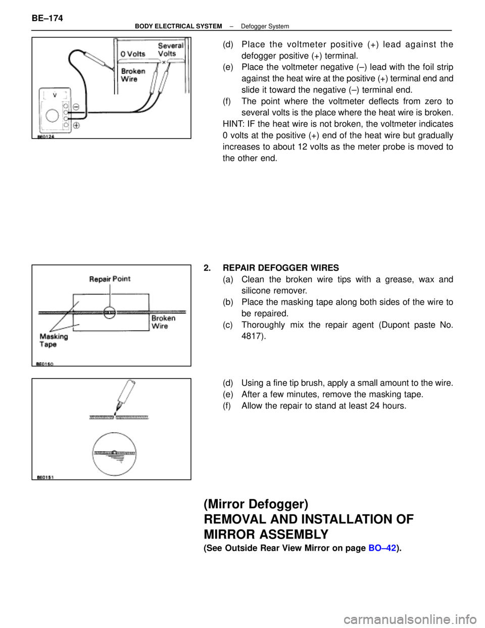
(d) Place the voltmeter positive (+) lead against thedefogger positive (+) terminal.
(e) Place the voltmeter negative (±) lead with the foil strip
against the heat wire at the positive (+) terminal end and
slide it toward the negative (±) terminal end.
(f) The point where the voltmeter deflects from zero to several volts is the place where the heat wire is broken.
HINT: IF the heat wire is not broken, the voltmeter indicates
0 volts at the positive (+) end of the heat wire but gradually
increases to about 12 volts as the meter probe is moved to
the other end.
2. REPAIR DEFOGGER WIRES (a) Clean the broken wire tips with a grease, wax andsilicone remover.
(b) Place the masking tape along both sides of the wire to be repaired.
(c) Thoroughly mix the repair agent (Dupont paste No. 4817).
(d) Using a fine tip brush, apply a small amount to the wire.
(e) After a few minutes, remove the masking tape.
(f) Allow the repair to stand at least 24 hours.
(Mirror Defogger)
REMOVAL AND INSTALLATION OF
MIRROR ASSEMBLY
(See Outside Rear View Mirror on page BO±42).
BE±174
±
BODY ELECTRICAL SYSTEM Defogger System
WhereEverybodyKnowsYourName
Page 561 of 4087
INSPECTION OF MIRROR DEFOGGER
INSPECT MIRROR DEFOGGER(a) Connect the positive (+) lead from the battery to terminal
7 and the negative (±) lead to terminal 8.
(b) Check that the mirror becomes warm.
HINT: It will take a short time for the mirror to become warm.
If the mirror does not become warm, replace the mirror as-
sembly.
Troubleshooting
You will find the cause of trouble more easily using the table shown below. In this table, the number indicate
the order priority of the causes in trouble. Check each part in the order s\
hown. If necessary, replace the parts.
See pageBE±4 ,20BE±4,20BE±4,22BE±172BE±173 ±±BE±173 ±±BE±174
TroubleParts
name
HEATER FuseMIR±HTR FuseDEFOG FuseDefogger SwitchDefogger RelayWire HarnessDefogger WiresCKE CoilMirror Defogger
All defogger systems do not operate.11234
Rear window defogger does not operate.312
Mirror Defogger does not operate.132
±
BODY ELECTRICAL SYSTEM Defogger SystemBE±175
WhereEverybodyKnowsYourName
Page 583 of 4087
MAINTENANCE OF TAPE PLAYER
Head Cleaning
Using a moist±type cleaning tape, clean the head surface, pinch rolle\
rs and capstans.
COMPACT DISC PLAYER
Compact Disc (hereafter called ºCDº) players use a laser beam pick±up\
to read the digital signals recorded
on the CD and reproduce analog signals of the music, etc. There are 4.7 in\
. (12 cm) and 3.2 in. (8 cm) CD
available, but it is recommended that you do not use 3.2 in. (8 cm) discs in the\
CD auto changer.
HINT: Never attempt to disassemble or oil any part of the player unit. Do not\
insert any object other than
a disc into the magagine.
NOTICE: CD players use on invisible laser laser beam which could cause hazardou\
s radiation expo-
sure. Be sure to operate the player correctly as instructed.
±
BODY ELECTRICAL SYSTEM Audio SystemBE±197
WhereEverybodyKnowsYourName
Page 602 of 4087

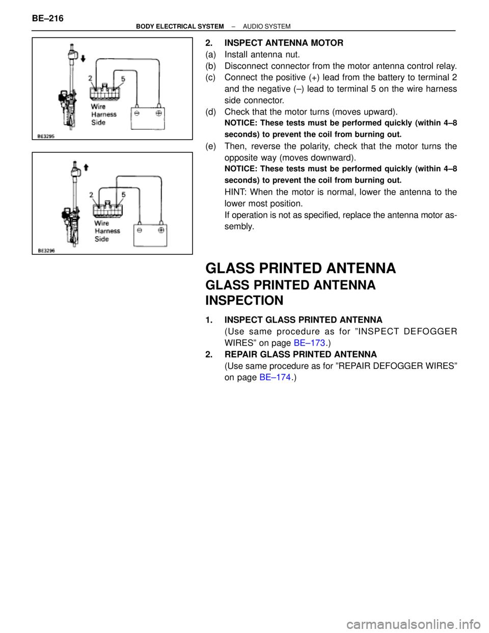
2. INSPECT ANTENNA MOTOR
(a) Install antenna nut.
(b) Disconnect connector from the motor antenna control relay.
(c) Connect the positive (+) lead from the battery to terminal 2and the negative (±) lead to terminal 5 on the wire harness
side connector.
(d) Check that the motor turns (moves upward).
NOTICE: These tests must be performed quickly (within 4±8
seconds) to prevent the coil from burning out.
(e) Then, reverse the polarity, check that the motor turns the opposite way (moves downward).
NOTICE: These tests must be performed quickly (within 4±8
seconds) to prevent the coil from burning out.
HINT: When the motor is normal, lower the antenna to the
lower most position.
If operation is not as specified, replace the antenna motor as-
sembly.
GLASS PRINTED ANTENNA
GLASS PRINTED ANTENNA
INSPECTION
1. INSPECT GLASS PRINTED ANTENNA(Use same procedure as for ºINSPECT DEFOGGER
WIRESº on page BE±173.)
2. REPAIR GLASS PRINTED ANTENNA (Use same procedure as for ºREPAIR DEFOGGER WIRESº
on page BE±174.)
BE±216
±
BODY ELECTRICAL SYSTEM AUDIO SYSTEM
WhereEverybodyKnowsYourName
Page 804 of 4087
PREPARATION
SST (SPECIAL SERVICE TOOLS)
IllustrationPart No.Part NameNote
09213±31021
Crankshaft Pulley
Puller
For removing steering wheel
RECOMMENDED TOOLS
IllustrationPart No.Part NameNote
09082±00015TOYOTA
Electrical Tester
09041±0030Torx Driver
T30
For removing and installing steering wheel pad and
power window motor
09042±00010Torx Socket
T30For removing and installing steering wheel pad and
power window motor
EQUIPMENT
Part NameNote
Voltmeter
Ammeter
Ohmmeter
Test lead
ThermometerWater temperature sender gauge, Engine oil level, Warning switch, Seat heater
SyphonBrake fluid level warning switch
Oil bathEngine oil level warning switch
Bulb (1.4 W)Coolant level warning ECU
Bulb (3.4 W)Fuel sender, gauge, Seat belt warning relay
Bulb (21 W)Turn signal flasher relay
Dry cell batteryFuel sender gauge
Heat lightSeat heater
Hexagon wrench (6 mm)Power seat
BE±8±
BODY ELECTRICAL SYSTEM Preparation
WhereEverybodyKnowsYourName
Page 805 of 4087
EQUIPMENT (Cont'd)
PartNote
Torque wrench
Clip removerFor removing cowl louver
Masking tapeRear window defogger wire
Tim foilRear window defogger wire
SSM (SPECIAL SERVICE MATERIALS)
Part NamePart No.Use etc.
Adhesive 1324,
Three bond 1324 or equivalent08833±00070Power seat housing set nut, Power seat slide and vertical
motor set screw
Adhesive 1344,
Three bond 1344,
Loctite 242 or equivalent
08833±00080Low oil pressure warning switch Water temperature
sender gauge
Dupont paste No. 4817±Rear window defogger wire
±
BODY ELECTRICAL SYSTEM PreparationBE±9
WhereEverybodyKnowsYourName
Page 849 of 4087

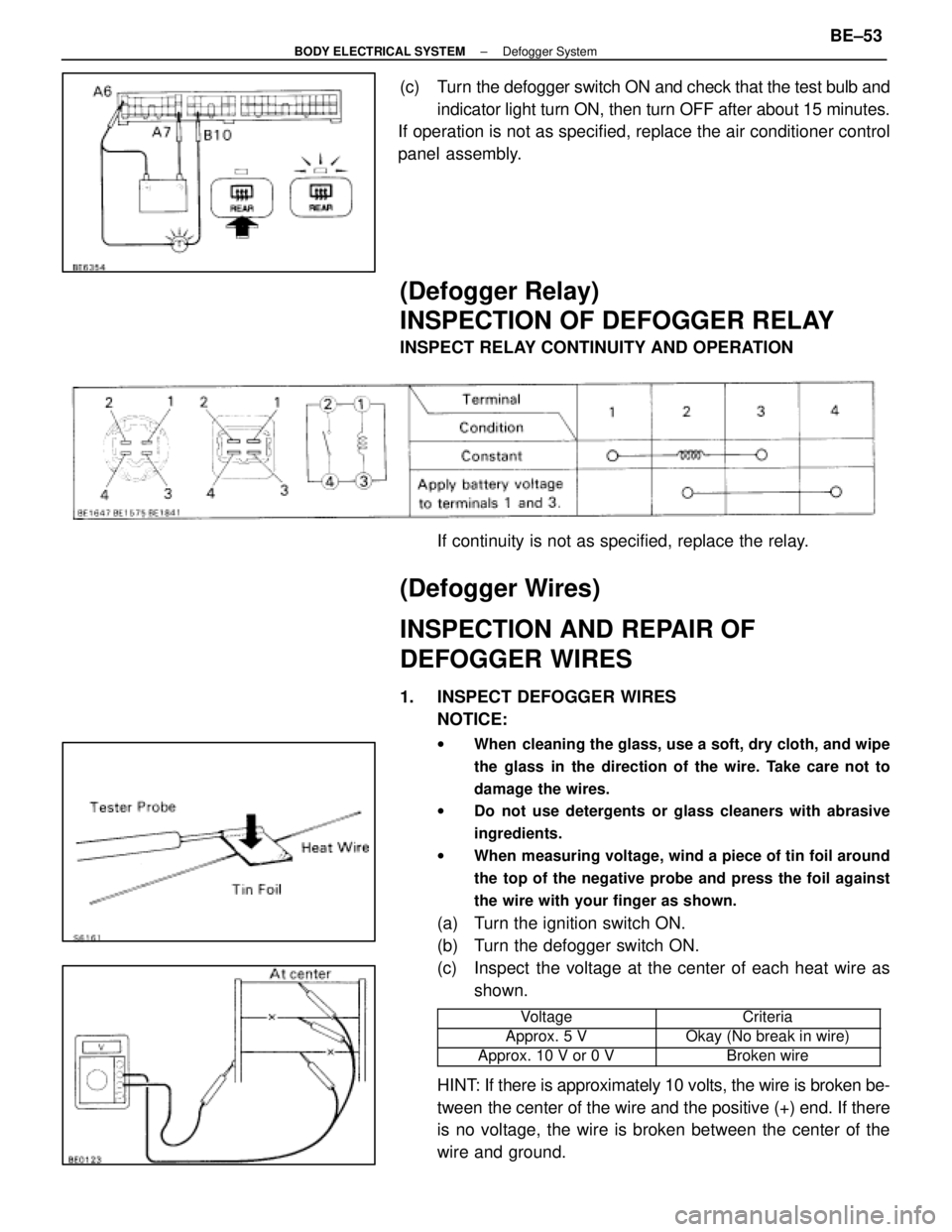
(c) Turn the defogger switch ON and check that the test bulb andindicator light turn ON, then turn OFF after about 15 minutes.
If operation is not as specified, replace the air conditioner control
panel assembly.
(Defogger Relay)
INSPECTION OF DEFOGGER RELAY
INSPECT RELAY CONTINUITY AND OPERATION
If continuity is not as specified, replace the relay.
(Defogger Wires)
INSPECTION AND REPAIR OF
DEFOGGER WIRES
1. INSPECT DEFOGGER WIRESNOTICE:
w When cleaning the glass, use a soft, dry cloth, and wipe
the glass in the direction of the wire. Take care not to
damage the wires.
w Do not use detergents or glass cleaners with abrasive
ingredients.
w When measuring voltage, wind a piece of tin foil around
the top of the negative probe and press the foil against
the wire with your finger as shown.
(a) Turn the ignition switch ON.
(b) Turn the defogger switch ON.
(c) Inspect the voltage at the center of each heat wire as
shown.
���������� ����������Voltage���������� ����������Criteria
����������Approx. 5 V����������Okay (No break in wire)���������� ����������Approx. 10 V or 0 V���������� ����������Broken wire
HINT: If there is approximately 10 volts, the wire is broken be-
tween the center of the wire and the positive (+) end. If there
is no voltage, the wire is broken between the center of the
wire and ground.
±
BODY ELECTRICAL SYSTEM Defogger SystemBE±53
WhereEverybodyKnowsYourName
Page 850 of 4087

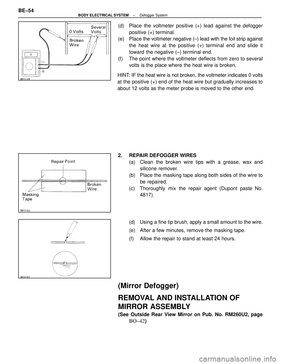
(d) Place the voltmeter positive (+) lead against the defoggerpositive (+) terminal.
(e) Place the voltmeter negative (±) lead with the foil strip against
the heat wire at the positive (+) terminal end and slide it
toward the negative (±) terminal end.
(f) The point where the voltmeter deflects from zero to several volts is the place where the heat wire is broken.
HINT: IF the heat wire is not broken, the voltmeter indicates 0 volts
at the positive (+) end of the heat wire but gradually increases to
about 12 volts as the meter probe is moved to the other end.
2. REPAIR DEFOGGER WIRES (a) Clean the broken wire tips with a grease, wax andsilicone remover.
(b) Place the masking tape along both sides of the wire to be repaired.
(c) Thoroughly mix the repair agent (Dupont paste No. 4817).
(d) Using a fine tip brush, apply a small amount to the wire.
(e) After a few minutes, remove the masking tape.
(f) Allow the repair to stand at least 24 hours.
(Mirror Defogger)
REMOVAL AND INSTALLATION OF
MIRROR ASSEMBLY
(See Outside Rear View Mirror on Pub. No. RM260U2, page
BO±42)
BE±54
±
BODY ELECTRICAL SYSTEM Defogger System
WhereEverybodyKnowsYourName