Page 45 of 4087
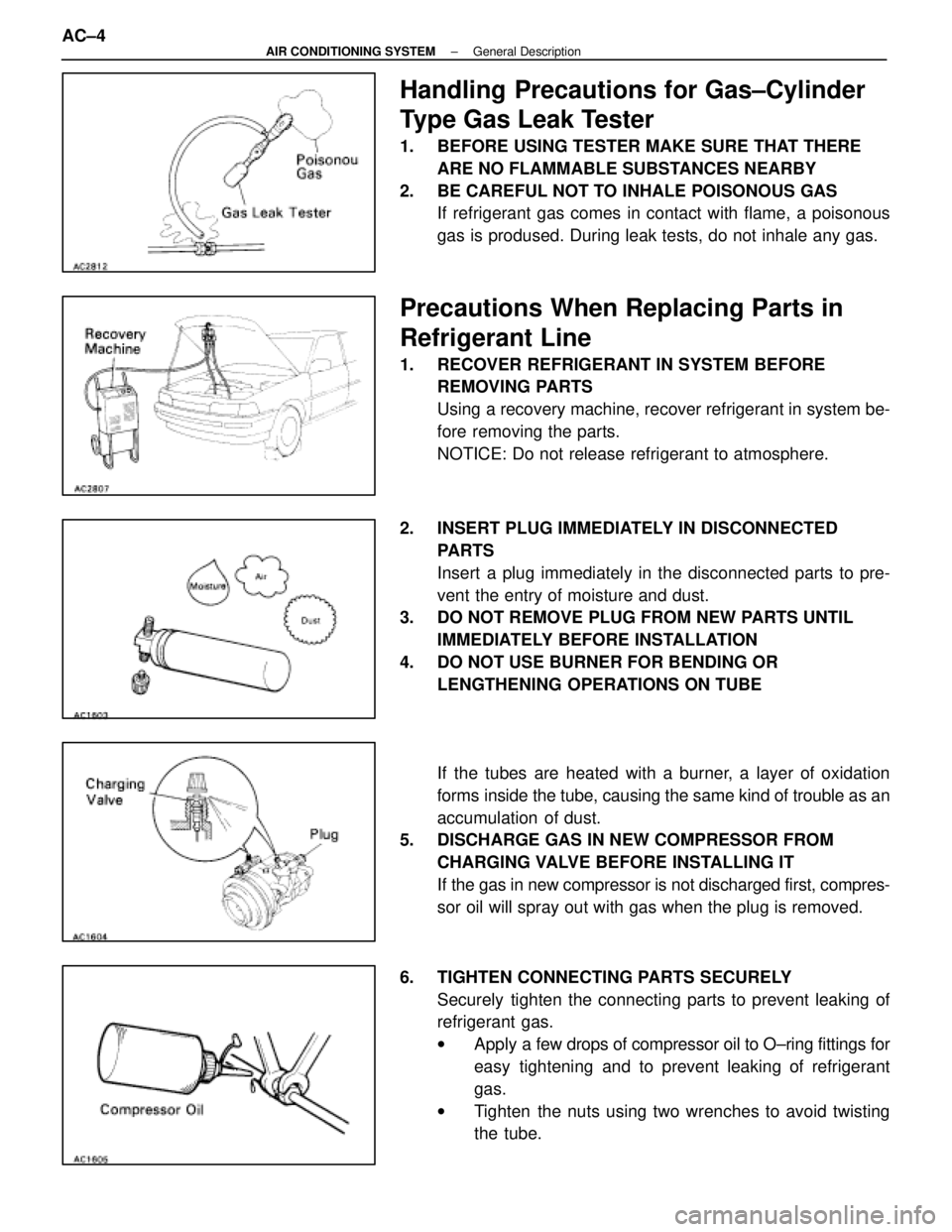
Handling Precautions for Gas±Cylinder
Type Gas Leak Tester
1. BEFORE USING TESTER MAKE SURE THAT THEREARE NO FLAMMABLE SUBSTANCES NEARBY
2. BE CAREFUL NOT TO INHALE POISONOUS GAS If refrigerant gas comes in contact with flame, a poisonous
gas is prodused. During leak tests, do not inhale any gas.
Precautions When Replacing Parts in
Refrigerant Line
1. RECOVER REFRIGERANT IN SYSTEM BEFOREREMOVING PARTS
Using a recovery machine, recover refrigerant in system be-
fore removing the parts.
NOTICE: Do not release refrigerant to atmosphere.
2. INSERT PLUG IMMEDIATELY IN DISCONNECTED PARTS
Insert a plug immediately in the disconnected parts to pre-
vent the entry of moisture and dust.
3. DO NOT REMOVE PLUG FROM NEW PARTS UNTIL
IMMEDIATELY BEFORE INSTALLATION
4. DO NOT USE BURNER FOR BENDING OR LENGTHENING OPERATIONS ON TUBE
If the tubes are heated with a burner, a layer of oxidation
forms inside the tube, causing the same kind of trouble as an
accumulation of dust.
5. DISCHARGE GAS IN NEW COMPRESSOR FROM
CHARGING VALVE BEFORE INSTALLING IT
If the gas in new compressor is not discharged first, compres-
sor oil will spray out with gas when the plug is removed.
6. TIGHTEN CONNECTING PARTS SECURELY Securely tighten the connecting parts to prevent leaking of
refrigerant gas.
wApply a few drops of compressor oil to O±ring fittings for
easy tightening and to prevent leaking of refrigerant
gas.
w Tighten the nuts using two wrenches to avoid twisting
the tube.
AC±4
±
AIR CONDITIONING SYSTEM General Description
WhereEverybodyKnowsYourName
Page 46 of 4087
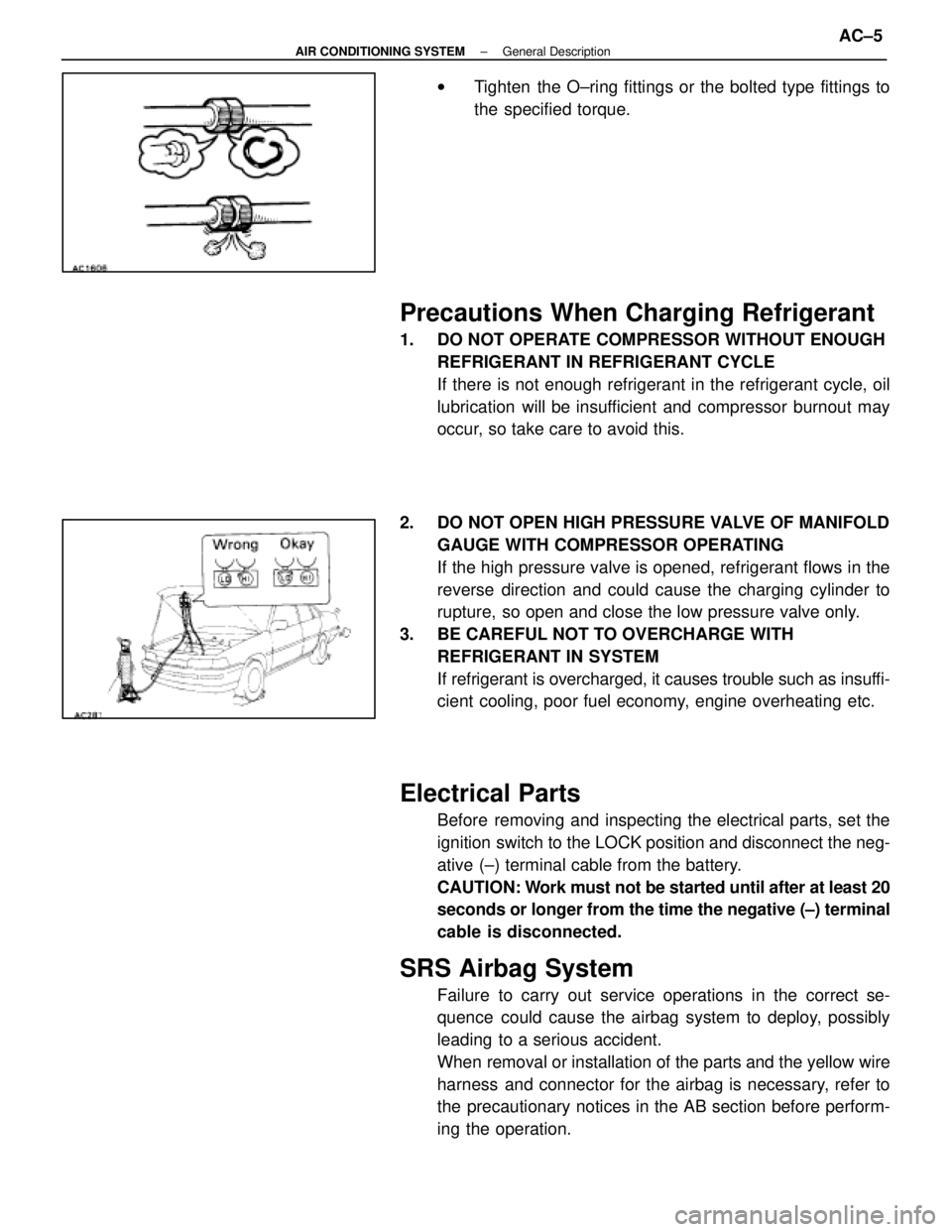
wTighten the O±ring fittings or the bolted type fittings to
the specified torque.
Precautions When Charging Refrigerant
1. DO NOT OPERATE COMPRESSOR WITHOUT ENOUGH
REFRIGERANT IN REFRIGERANT CYCLE
If there is not enough refrigerant in the refrigerant cycle, oil
lubrication will be insufficient and compressor burnout may
occur, so take care to avoid this.
2. DO NOT OPEN HIGH PRESSURE VALVE OF MANIFOLD GAUGE WITH COMPRESSOR OPERATING
If the high pressure valve is opened, refrigerant flows in the
reverse direction and could cause the charging cylinder to
rupture, so open and close the low pressure valve only.
3. BE CAREFUL NOT TO OVERCHARGE WITH REFRIGERANT IN SYSTEM
If refrigerant is overcharged, it causes trouble such as insuffi-
cient cooling, poor fuel economy, engine overheating etc.
Electrical Parts
Before removing and inspecting the electrical parts, set the
ignition switch to the LOCK position and disconnect the neg-
ative (±) terminal cable from the battery.
CAUTION: Work must not be started until after at least 20
seconds or longer from the time the negative (±) terminal
cable is disconnected.
SRS Airbag System
Failure to carry out service operations in the correct se-
quence could cause the airbag system to deploy, possibly
leading to a serious accident.
When removal or installation of the parts and the yellow wire
harness and connector for the airbag is necessary, refer to
the precautionary notices in the AB section before perform-
ing the operation.
±
AIR CONDITIONING SYSTEM General DescriptionAC±5
WhereEverybodyKnowsYourName
Page 55 of 4087
EQUIPMENT
�������������� ��������������Part Name������������������\
����� ������������������\
�����Note
�������������� �
�������������
��������������Voltmeter������������������\
����� �
������������������\
����
������������������\
�����Measures voltage�������������� �
�������������
��������������Ammeter
������������������\
����� �
������������������\
����
������������������\
�����Measures current
�������������� ��������������Ohmmeter������������������\
����� ������������������\
�����Measures resistance
LUBRICANT
ItemCapacityClassificationItemccfl. ozClassification
Compressor oil
When replacing receiver
When replacing condenser
When replacing evaporator
20
40±50
40±500.7
1.4±1.7
1.4±1.7
ND OIL 6,
SUNISO No. 5GS or equivalent
AC±14±
AIR CONDITIONING SYSTEM Preparation Cooling System
WhereEverybodyKnowsYourName
Page 56 of 4087
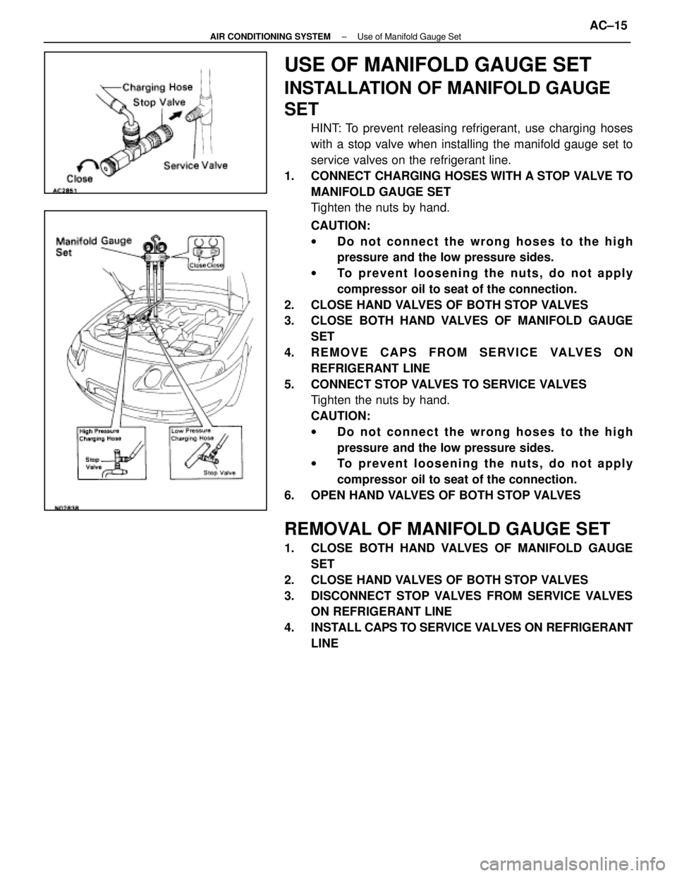
USE OF MANIFOLD GAUGE SET
INSTALLATION OF MANIFOLD GAUGE
SET
HINT: To prevent releasing refrigerant, use charging hoses
with a stop valve when installing the manifold gauge set to
service valves on the refrigerant line.
1. CONNECT CHARGING HOSES WITH A STOP VALVE TO MANIFOLD GAUGE SET
Tighten the nuts by hand.
CAUTION:
wDo not connect the wrong hoses to the high
pressure and the low pressure sides.
w To prevent loosening the nuts, do not apply
compressor oil to seat of the connection.
2. CLOSE HAND VALVES OF BOTH STOP VALVES
3. CLOSE BOTH HAND VALVES OF MANIFOLD GAUGE SET
4. REMOVE CAPS FROM SERVICE VALVES ON REFRIGERANT LINE
5. CONNECT STOP VALVES TO SERVICE VALVES Tighten the nuts by hand.
CAUTION:
wDo not connect the wrong hoses to the high
pressure and the low pressure sides.
w To prevent loosening the nuts, do not apply
compressor oil to seat of the connection.
6. OPEN HAND VALVES OF BOTH STOP VALVES
REMOVAL OF MANIFOLD GAUGE SET
1. CLOSE BOTH HAND VALVES OF MANIFOLD GAUGE SET
2. CLOSE HAND VALVES OF BOTH STOP VALVES
3. DISCONNECT STOP VALVES FROM SERVICE VALVES ON REFRIGERANT LINE
4. INSTALL CAPS TO SERVICE VAL VES ON REFRIGERANT
LINE
±
AIR CONDITIONING SYSTEM Use of Manifold Gauge SetAC±15
WhereEverybodyKnowsYourName
Page 57 of 4087
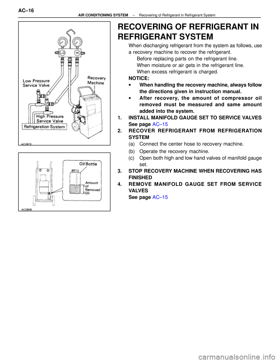
RECOVERING OF REFRIGERANT IN
REFRIGERANT SYSTEM
When discharging refrigerant from the system as follows, use
a recovery machine to recover the refrigerant.Before replacing parts on the refrigerant line.
When moisture or air gets in the refrigerant line.
When excess refrigerant is charged.
NOTICE:
w When handling the recovery machine, always follow
the directions given in instruction manual.
w After recovery, the amount of compr essor oil
removed must be measured and same am ount
added into the system.
1. INSTALL MANIFOLD GAUGE SET TO SERVICE VALVES See page AC±15
2. RECOVER REFRIGERANT FROM REFRIGERATION
SYSTEM
(a) Connect the center hose to recovery machine.
(b) Operate the recovery machine.
(c) Open both high and low hand valves of manifold gauge set.
3. STOP RECOVERY MACHINE WHEN RECOVERING HAS FINISHED
4. REMOVE MANIFOLD GAUGE SET FROM SERVICE VA LV E S
See page AC±15
AC±16
±
AIR CONDITIONING SYSTEM Recovering of Refrigerant in Refrigerant System
WhereEverybodyKnowsYourName
Page 138 of 4087
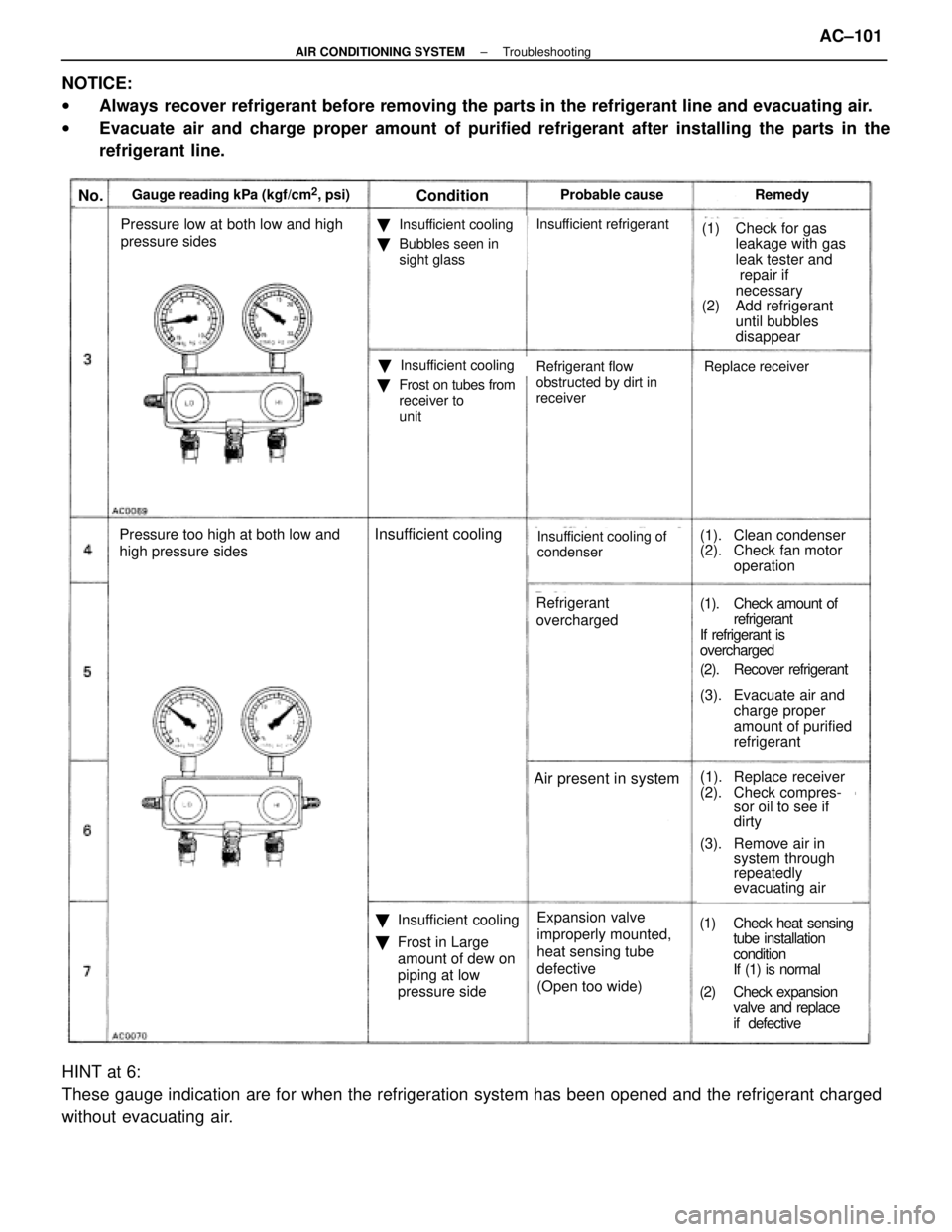
No.Gauge reading kPa (kgf/cm2, psi)ConditionProbable causeRemedy
Pressure low at both low and high
pressure sides
Pressure too high at both low and
high pressure sides
�Insufficient cooling
�Bubbles seen in
sight glass
�Insufficient cooling
�Frost on tubes from
receiver to
unit
Replace receiver
Insufficient refrigerant(1) Check for gas
leakage with gas
leak tester and
repair if
necessary
(2) Add refrigerant
until bubbles
disappear
Refrigerant flow
obstructed by dirt in
receiver
Insufficient coolingInsufficient cooling of
condenser(1). Clean condenser
(2). Check fan motoroperation
(1). Check amount ofrefrigerant
If refrigerant is
overcharged
(2). Recover refrigeran
t
(3). Evacuate air and charge proper
amount of purified
refrigerant
Refrigerant
overcharged
(1). Replace receiver
(2). Check compres- sor oil to see if
dirtyAir present in system
�Insufficient cooling
� Frost in Large
amount of dew on
piping at low
pressure side Expansion valve
improperly mounted,
heat sensing tube
defective
(Open too wide)(1) Check heat sensing
tube installation
condition
If (1) is normal
(2) Check expansion valve and replace
if defective
(3). Remove air insystem through
repeatedly
evacuating air
NOTICE:
wAlways recover refrigerant before removing the parts in the refrigerant line a\
nd evacuating air.
w Evacuate air and charge proper amount of purified refrigerant after installing th\
e parts in the
refrigerant line.
HINT at 6:
These gauge indication are for when the refrigeration system has been op\
ened and the refrigerant charged
without evacuating air.
±
AIR CONDITIONING SYSTEM TroubleshootingAC±101
WhereEverybodyKnowsYourName
Page 156 of 4087
INSTALLATION OF RECEIVER
1. INSTALL RECEIVER IN RECEIVER HOLDERInstall the receiver in the receiver holder with the one bolt.
2. INSTALL TWO LIQUID TUBES ON RECEIVER Install the two liquid tubes on the receiver with the two bolts.
Specified torque: 5.4 N Vm (55 kgf Vcm, 4 ft Vlbf)
NOTICE: Do not remove the caps until the tubes are con-
nected.
3. REPLENISH COMPRESSOR OIL IF RECEIVER HAS BEEN REPLACED
Add 20 cc (0.7 fl.oz.)
Compressor oil: ND OIL 6,
SUNISO NO. 5 GS or equivalent
4. EVACUATE AIR IN REFRIGERATION SYSTEM ANDCHARGE WITH REFRIGERANT
See page AC±17
Specified amount: 950 + 50 g (33.44 + 1.76 oz)
5. INSPECT FOR LEAKAGE OF REFRIGERANT
Using a gas leak tester, check for leakage of refrigerant.
If there is leakage, check the tightening torque at the joints.
6. INSPECT A/C OPERATION
7. INSTALL HEADLIGHT See page BE±37
±
AIR CONDITIONING SYSTEM ReceiverAC±119
WhereEverybodyKnowsYourName
Page 158 of 4087
INSTALLATION OF CONDENSER
1. INSTALL CONDENSERInstall the condenser with two nuts.
2. INSTALL LIQUID TUBE AND DISCHARGE TUBE
Install both tubes with two bolts.
Specified torque:
Discharge tube 10 N Vm (100 kgf Vcm, 7 ft Vlbf)
Liquid tube 10 N Vm (100 kgf Vcm, 7 ft Vlbf)
NOTICE: Don't remove caps until the tube is installed.
3. IF CONDENSER WAS REPLACED, ADD COMPRESSOR OIL TO COMPRESSOR
ADD 40±50 cc (1.4±1.7 ft.oz.)
Compressor oil: ND OIL 6,
SUNISO NO. 5 GS or equivalent
4. EVACUATE AIR IN REFRIGERATION SYSTEM ANDCHARGE WITH REFRIGERANT
See page AC±17
Specified amount: 950 + 50 g (33.44 + 1.76 oz)
5. INSPECT FOR LEAKAGE OF REFRIGERATN
Using a gas leak tester, check for leakage of refrigerant.
6. INSTALL REMOVAL PARTS Install the removal parts in reverse order of removal proce-
dure.
±
AIR CONDITIONING SYSTEM CondenserAC±121
WhereEverybodyKnowsYourName