Page 378 of 4087
6. INSTALL EXTENSION HOUSING REAR OIL SEAL
(a) Coat the lip of oil seal with MP grease.
(b) Using SST and a hammer, drive in a new oil seal with the lipfacing downward.
SST 09309±37010
Oil seal depth from flat end:
0±0.3 mm (0±0.012 in.)
7. INSTALL TRANSMISSION OUTPUT FLANGE
(a) Using SST and a hammer, drive in a new oil seal.SST 09517±36010
(b) Install the output flange and 2 washers.
(c) Using SST, install and torque a new nut. SST 09060±20010
Torque: 123 N Vm (1,250 kgf Vcm, 90 ft Vlbf)
HINT: Shift the shift lever to the P position.
(d) Using a hammer and chisel, stake the nut.
8. INSTALL PROPELLER SHAFT (See pages PR±12)
9. INSTALL FRONT EXHAUST PIPE AND HEAT INSULATOR (See page EG±204)
10. FILL WITH ATF
11. CHECK FLUID LEVEL (See page AT±47)
±
A304E (1UZ±FE) AUTOMATIC TRANSMISSION EXTENSION HOUSINGAT±15
WhereEverybodyKnowsYourName
Page 382 of 4087
VALVE BODY
VALVE BODY REMOVAL
AT0GG±02
1. DRAIN ATF
2. REMOVE FRONT EXHAUST PIPE(See pages EG±204)
3. REMOVE OIL PAN
(a) Remove the 19 bolts.
(b) Install the blade of SST between the transmission case and oil pan, cut off applied sealer.
SST 09032±00100
NOTICE: Be careful not to damage the oil pan flange.
4. EXAMINE PARTICLES IN PANRemove the magnets and use them to collect steel particles.
Carefully look at the foreign matter and particles in the pan
and on the magnets to anticipate the type of wear you will find
in the transmission:
Steel (magnetic) 0 bearing, gear and clutch plate wear
Brass (non±magnetic) 0 bushing wear
5. REMOVE OIL STRAINER Remove the 3 bolts holding the oil strainer to the valve body.
6. REMOVE SOLENOID WIRING
(a) Remove the 2 bolts and the clamp.
(b) Disconnect the 4 connectors from the solenoid valves.
±
A304E (1UZ±FE) AUTOMATIC TRANSMISSION VALVE BODYAT±19
WhereEverybodyKnowsYourName
Page 385 of 4087
4. CONNECT SOLENOID VALVE CONNECTORS
5. INSTALL OIL STRAINER AND GASKETSInstall the oil strainer and torque the 3 bolts.
Torque: 10 N Vm (100 kgf Vcm, 7 ft Vlbf)
6. INSTALL OIL PAN
(a) Install the 4 magnets in the indentations of the oil pan, as
shown in the illustration.
(b) Remove any FIPG material and be careful not to drop oil on the contacting surfaces of the transmission case and oil pan.
(c) Apply FIPG to the oil pan, as shown in the illustration.
FIPG:
Part No. 08826±00090, THREE BOND 1281 or equivalent
(d) Install the oil pan to the transmission case and torque the 19bolts.
Torque: 7.4 N Vm (75 kgf Vcm, 65 in. Vlbf)
7. INSTALL FRONT EXHAUST PIPE
(See page EG±204)
8. CHECK FLUID LEVEL
AT±22
±
A304E (1UZ±FE) AUTOMATIC TRANSMISSION VALVE BODY
WhereEverybodyKnowsYourName
Page 395 of 4087

HOW TO PROCEED WITH TROUBLESHOOTING
AT09N±0D
1. CUSTOMER PROBLEM ANALYSISUsing the customer problem analysis check sheet for reference, ask the c\
ustomer in as much detail as
possible about the problem.
2. CHECK AND CLEAR THE DIAGNOSTIC TROUBLE CODES (PRECHECK) Before confirming the problem symptom, first check if there are any diagnostic\
trouble malfunction codes
stored in memory. When there are malfunction codes, make a note of them, then clear them\
and proceed
to ª3. Problem Symptom Confirmationº.
3. PROBLEM SYMPTOM CONFIRMATION Confirm the problem symptoms.
4. SYMPTOM SIMULATION If the problem does not reappear, be sure to simulate the problem by mainly checking the circuits indica\
ted
by the diagnostic trouble code in step 2., using ªProblem Simulation me\
thodº.
5. DIAGNOSTIC TROUBLE CODE CHECK Check the diagnostic trouble codes. Check if there is abnormality in the\
sensors or the wire harness.
If a malfunction code is output, proceed to ª6. Diagnostic Trouble Code Chartº.
If the normal code is output, proceed to ª11. Matrix Chart of Problem Symptomsº.
Be sure to proceed to ª6. Diagnostic Trouble Code Chartº after the steps 2. and 3. are completed.
If troubleshooting is attempted only by following the malfunction code sto\
red in the memory is output, errors
could be made in the diagnosis.
6. DIAGNOSTIC TROUBLE CODE CHART If a malfunction code is confirmed in the diagnostic trouble code check, p\
roceed to the inspection proce-
dure indicated by the matrix chart for each diagnostic trouble code.
7. PRELIMINARY CHECK Carry out a preliminary check of the transmission oil level, throttle ca\
ble adjustment, etc.
8. SHIFT POSITION SIGNAL CHECK
Carry out the shift position signal check when the transmission gears do\
not up±shift, down±shift or lock±
up. This is to check the output condition from the ECM to each solenoid. If the r\
esults are NG, then it is
likely that the trouble is in the electrical system (particularly in th\
e sensors or the ECM).
Proceed to Part 1 (Electrical System) under ª11. Matrix Chart of Problem Symptomsº. If all the circuits speci-
fied in Part 1 are OK, check the ECM and replace it.
9. MECHANICAL SYSTEM TEST (Stall Test, Time Lag Test, Line Pressure Test, Accumulator Back Pressure Test)
If the malfunction is found in the stall test, time lag test, line press\
ure test or accumulator back pressure
test, check the parts indicated in the respective tests. If the problem is th\
at ªshift shock is largeº, perform
the accumulator back pressure test.
10. MANUAL SHIFTING TEST If the results of the manual driving test are NG, it is likely that the trouble is in the mechanical system or
hydraulic system. Proceed to Part 2 (Mechanical System) under the Matrix Chart \
of Problem Symptoms.
AT±32
±
A304E (1UZ±FE) AUTOMATIC TRANSMISSION TROUBLESHOOTING
WhereEverybodyKnowsYourName
Page 442 of 4087
7. REMOVE WIND DEFLECTOR(a) Slide the drive cable backward.
(b) Remove four screws and the deflector.
8. REMOVE CABLE GUIDE CASING (a) Remove two screws and the guide rail cover.
(b) Remove two screws from the drive rail.
(c) Slide the drive cable forward.
(d) Pull down the roof handlining.
(e) Disconnect front side of the drain hose.
HINT: Disconnect the drain hose from the sliding roof
housing side.
(f) Remove the sliding roof control relay.
(g) Remove the two nuts from the sliding roof housing.
(h) Remove the cable guide casing gradually from bothsides.
NOTICE: Be careful that the oily cable doesn't fall off.
9. REMOVE ROOF DRIP CHANNEL (a) Remove two screws.
(b) Pull the channel forward to remove it.
10. REMOVE SUNSHADE TRIM While raising the drive rail, pull the trim forward to remove it.
BO±86
±
BODY Moon Roof (Sliding Roof)
WhereEverybodyKnowsYourName
Page 461 of 4087
REAR SPOILER
COMPONENTS
REMOVAL AND INSTALLATION
1. REMOVE DOOR TRIM
2. REMOVE REAR SPOILERDisconnect the connector, remove five nuts and the spoiler.
3. INSTALL REAR SPOILER Connect the connector, install five nuts and the spoiler.
4. INSTALL DOOR TRIM
±
BODY SpoilerBO±105
WhereEverybodyKnowsYourName
Page 517 of 4087

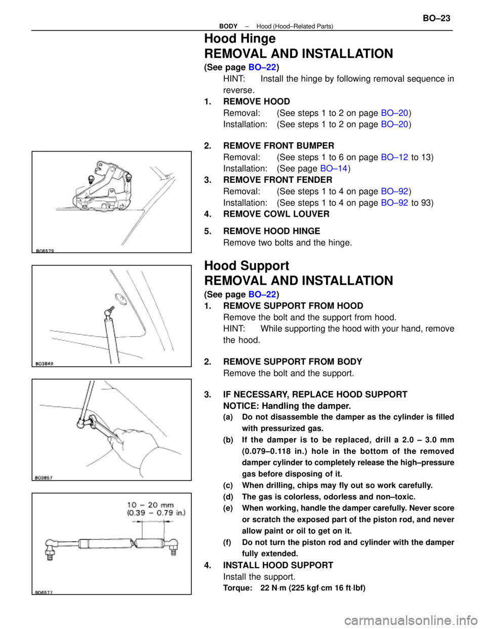
Hood Hinge
REMOVAL AND INSTALLATION
(See page BO±22)
HINT: Install the hinge by following removal sequence in
reverse.
1. REMOVE HOOD Removal: (See steps 1 to 2 on page BO±20)
Installation: (See steps 1 to 2 on page BO±20)
2. REMOVE FRONT BUMPER Removal: (See steps 1 to 6 on page BO±12 to 13)
Installation: (See page BO±14)
3. REMOVE FRONT FENDER Removal: (See steps 1 to 4 on page BO±92)
Installation: (See steps 1 to 4 on page BO±92 to 93)
4. REMOVE COWL LOUVER
5. REMOVE HOOD HINGE
Remove two bolts and the hinge.
Hood Support
REMOVAL AND INSTALLATION
(See page BO±22)
1. REMOVE SUPPORT FROM HOOD Remove the bolt and the support from hood.
HINT: While supporting the hood with your hand, remove
the hood.
2. REMOVE SUPPORT FROM BODY Remove the bolt and the support.
3. IF NECESSARY, REPLACE HOOD SUPPORT NOTICE: Handling the damper.
(a) Do not disassemble the damper as the cylinder is filled
with pressurized gas.
(b) If the damper is to be repl aced, drill a 2.0 ± 3.0 mm
(0.079±0.118 in.) hole in the bottom of the removed
damper cylinder to completely release the high±pressure
gas before disposing of it.
(c) When drilling, chips may fly out so work carefully.
(d) The gas is colorless, odorless and non±toxic.
(e) When working, handle the damper carefully. Never score or scratch the exposed part of the piston rod, and never
allow paint or oil to get on it.
(f) Do not turn the piston rod and cylinder with the damper fully extended.
4. INSTALL HOOD SUPPORTInstall the support.
Torque: 22 N Vm (225 kgf Vcm 16 ft Vlbf)
±
BODY Hood (Hood±Related Parts)BO±23
WhereEverybodyKnowsYourName
Page 559 of 4087

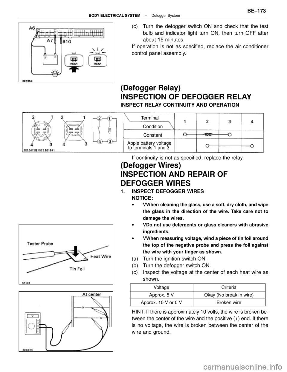
(c) Turn the defogger switch ON and check that the testbulb and indicator light turn ON, then turn OFF after
about 15 minutes.
If operation is not as specified, replace the air conditioner
control panel assembly.
(Defogger Relay)
INSPECTION OF DEFOGGER RELAY
INSPECT RELAY CONTINUITY AND OPERATION
Terminal
ConditionConstant
Apple battery voltage to terminals 1 and 3.
If continuity is not as specified, replace the relay.
(Defogger Wires)
INSPECTION AND REPAIR OF
DEFOGGER WIRES
1. INSPECT DEFOGGER WIRES
NOTICE:
w VWhen cleaning the glass, use a soft, dry cloth, and wipe
the glass in the direction of the wire. Take care not to
damage the wires.
w VDo not use detergents or glass cleaners with abrasive
ingredients.
w VWhen measuring voltage, wind a piece of tin foil around
the top of the negative probe and press the foil against
the wire with your finger as shown.
(a) Turn the ignition switch ON.
(b) Turn the defogger switch ON.
(c) Inspect the voltage at the center of each heat wire as
shown.
VoltageCriteria
Approx. 5 VOkay (No break in wire)
Approx. 10 V or 0 VBroken wire
HINT: If there is approximately 10 volts, the wire is broken be-
tween the center of the wire and the positive (+) end. If there
is no voltage, the wire is broken between the center of the
wire and ground.
±
BODY ELECTRICAL SYSTEM Defogger SystemBE±173
WhereEverybodyKnowsYourName