Page 24 of 4087
![LEXUS SC300 1991 Service Repair Manual
[2] HEAT METHOD: When the problem seems to occur when the suspect area is heated.
Heat the component that is the likely cause of the malfunc-
tion with a hair dryer or similar object. Check to see if LEXUS SC300 1991 Service Repair Manual
[2] HEAT METHOD: When the problem seems to occur when the suspect area is heated.
Heat the component that is the likely cause of the malfunc-
tion with a hair dryer or similar object. Check to see if](/manual-img/36/57052/w960_57052-23.png)
[2] HEAT METHOD: When the problem seems to occur when the suspect area is heated.
Heat the component that is the likely cause of the malfunc-
tion with a hair dryer or similar object. Check to see if the
malfunction occurs.
NOTICE:
(1) Do not heat to more than 60°C (140 °F).
(Temperature limit that no damage is done to the
component).
(2) Do not apply heat directly to parts in the ECU.
[3] WATER SPRINKLING METHOD: When the malfunction seems to occur on a
rainy\
day or in a high±humidity condition.
Sprinkle w ater onto the vehicle and check to see if the mal-
function occurs.
NOTICE:
(1) Never sprinkle water directly into the engine compartment, but indirectly change the tempera-
ture and humidity by applying water spray onto
the radiator front surface.
(2) Never apply water directly onto the electronic components.
(Service hint)
If a vehicle is subject to water leakage, the leaked water
may contaminate the ECU. When testing a vehicle with a
water leakage problem, special caution must be used.
[4] OTHER: When the malfunction seems to occur when electrical load is excessive.
Turn on all electrical loads including the heater blower,
head lights, rear window defogger, etc. and check to see
if the malfunction occurs.
±
INTRODUCTION TITLE±NAMEIN±21
WhereEverybodyKnowsYourName
Page 41 of 4087

R±12 AIR CONDITIONER SYSTEM RETROFIT ± AC001±98 April 3, 1998
Page 4 of 4
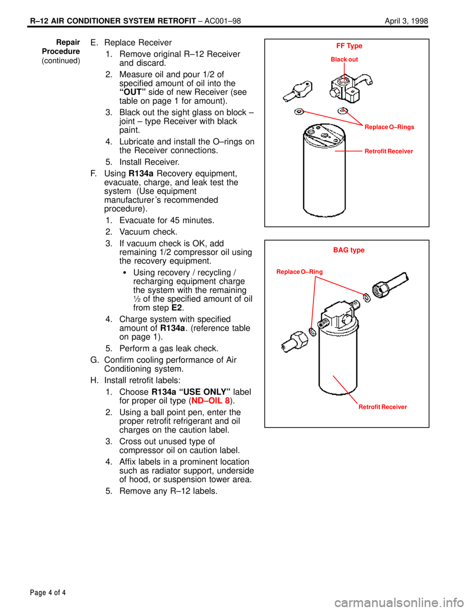
E. Replace Receiver
1. Remove original R±12 Receiverand discard.
2. Measure oil and pour 1/2 of specified amount of oil into the
ªOUTº side of new Receiver (see
table on page 1 for amount).
3. Black out the sight glass on block ± joint ± type Receiver with black
paint.
4. Lubricate and install the O±rings on the Receiver connections.
5. Install Receiver.
F. Using R134a Recovery equipment,
evacuate, charge, and leak test the
system (Use equipment
manufacturer 's recommended
procedure).
1. Evacuate for 45 minutes.
2. Vacuum check.
3. If vacuum check is OK, add remaining 1/2 compressor oil using
the recovery equipment.
� Using recovery / recycling /
recharging equipment charge
the system with the remaining
½ of the specified amount of oil
from step E2.
4. Charge system with specified amount of R134a. (reference table
on page 1).
5. Perform a gas leak check.
G. Confirm cooling performance of Air Conditioning system.
H. Install retrofit labels:
1. Choose R134a ªUSE ONLYº label
for proper oil type ( ND±OIL 8).
2. Using a ball point pen, enter the proper retrofit refrigerant and oil
charges on the caution label.
3. Cross out unused type of compressor oil on caution label.
4. Affix labels in a prominent location such as radiator support, underside
of hood, or suspension tower area.
5. Remove any R±12 labels.Repair
Procedure
(continued)FF Type
Black out
Replace O±Rings
Retrofit Receiver
BAG type
Replace O±Ring
Retrofit Receiver
WhereEverybodyKnowsYourName
Page 144 of 4087
A/C UNIT
REMOVAL OF A/C UNIT
1. RECOVER REFRIGERANT IN SYSTEMSee page AC±16
2. REMOVE ENGINE See page EM±118
3. REMOVE WATER VALVE
See page AC±127
4. REMOVE BRAKE TUBES BRACKET MOUNTING BOLTS FROM DUSH PANEL
5. REMOVE EVAPORATOR See page AC±122
6. REMOVE WATER HOSE FROM HEATER RADIATOR
7. REMOVE INSULATOR RETAINER Remove the two bolts and the retainer.
8. REMOVE INSTRUMENT PANEL REINFORCEMENT See page BO±109
9. REMOVE FLOOR CARPET See page BO±118
10. REMOVE REAR AIR DUCTS Remove the nut and the air duct.
11. REMOVE HEATER TO RESISTER NO. 3 DUCT Remove the screw and the duct.
±
AIR CONDITIONING SYSTEM A/C UnitAC±107
WhereEverybodyKnowsYourName
Page 145 of 4087
12. REMOVE CONNECTOR BRACKET FROM UNDER SIDEOF BLOWER MOTOR
Remove the two screws and the bracket.
13. REMOVE A/C UNIT
(a) Disconnect connectors from the unit.
(b) Remove the six bolts and the A/C unit.
INSTALLATION OF A/C UNIT
1. INSTALL A/C UNIT
(a) Match the standard holes of the A/C unit with those on the vehicle.
HINT:
wV
Pull the drain hose of the A/C unit forward until the
yellow paint on the hose is visible in the engine
compartment.
w V
Insert the drain hose into the engine compartment hose
until the match marks are aligned.
(b) Tighten six bolts.
2. INSTALL CONNECTOR BRACKET
3. INSTALL HEATER TO RESISTER NO. 3 DUCT
4. INSTALL REAR AIR DUCTS
5. INSTALL FLOOR CARPET
6. INSTALL INSULATOR RETAINER
7. INSTALL WATER HOSE TO HEATER RADIATOR
8. INSTALL BRAKE TUBE BRACKET MOUNTING BOLTS
9. INSTALL WATER VALVE See page AC±127
AC±108
±
AIR CONDITIONING SYSTEM Troubleshooting
WhereEverybodyKnowsYourName
Page 157 of 4087
CONDENSER
ON±VEHICLE INSPECTION
1. INSPECT CONDENSER FINS FOR BLOCKAGE OR
DAMAGE
If the fins are clogged, wash them with water and dry with
compressed air.
NOTICE: Be careful not to damage the fins.
If the fins are bent, straighten them with a screwdriver or pli-
ers.
2. INSPECT CONDENSER AND FITTINGS FOR LEAKAGE Using a gas leak tester, check for leakage.
If there is leakage, check the tightening torque at the joints.
REMOVAL OF CONDENSER
1. RECOVER REFRIGERANT IN REFRIGERATION SYSTEMSee page AC±16
2. REMOVE BATTERY
3. REMOVE CONDENSER UPPER COVER AND RADIATOR FITTING BOLT
4. REMOVE UNDER COVER AND AIR FLOW COVER
5. REMOVE LIQUID TUBE AND SUCTION TUBE Remove two bolts and both tubes.
NOTICE: Cap open the fittings immediately to keep mois-
ture out of the system.
6. REMOVE CONDENSER Remove two nuts and lean the radiator backward, then re-
move the condenser.
AC±120
±
AIR CONDITIONING SYSTEM Condenser
WhereEverybodyKnowsYourName
Page 162 of 4087
HEATER RADIATOR
REMOVAL OF HEATER RADIATOR
1. SET TEMPERATURE CONTROL SWITCH TO MAX COOL
2. REMOVE A/C UNITSee page AC±107
3. REMOVE HATER RADIATOR
(a) Remove the two screws and the plate.
(b) Remove the two screws and the clamps.
(c) Pull the radiator out.
INSPECTION OF HEATER RADIATOR
INSPECT FINS FOR BLOCKAGE If the fins are clogged, clean them with compressed air.
INSTALLATION OF HEATER RADIATOR
1. INSTALL HEATER RADIATOR TO A/C UNIT(a) Put the radiator in the A/C until.
(b) Install the clamps with two screws.
(c) Install the plate with two screws.
2. INSTALL A/C UNIT
See page AC±108
±
AIR CONDITIONING SYSTEM Heater RadiatorAC±125
WhereEverybodyKnowsYourName
Page 483 of 4087

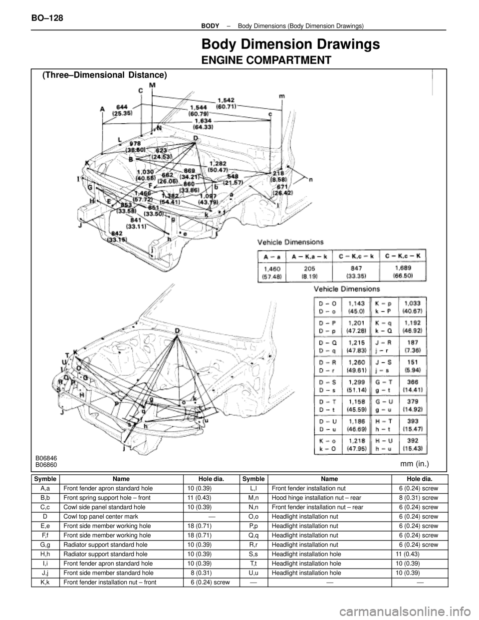
Body Dimension Drawings
ENGINE COMPARTMENT
(Three±Dimensional Distance)
mm (in.)B06846
B06860
Symble
NameHole dia.SymbleNameHole dia.
A,aFront fender apron standard hole10 (0.39)L,lFront fender installation nut6 (0.24) screw
B,bFront spring support hole ± front11 (0.43)M,nHood hinge installation nut ± rear8 (0.31) screw
C,cCowl side panel standard hole10 (0.39)N,nFront fender installation nut ± rear6 (0.24) screw
DCowl top panel center mark'O,oHeadlight installation nut6 (0.24) screw
E,eFront side member working hole18 (0.71)P, pHeadlight installation nut6 (0.24) screw
F, fFront side member working hole18 (0.71)Q,qHeadlight installation nut6 (0.24) screw
G,gRadiator support standard hole10 (0.39)R,rHeadlight installation nut6 (0.24) screw
H,hRadiator support standard hole10 (0.39)S,sHeadlight installation hole11 (0.43)
I,iFront fender apron standard hole10 (0.39)T, tHeadlight installation hole10 (0.39)
J,jFront side member standard hole8 (0.31)U,uHeadlight installation hole10 (0.39)
K,kFront fender installation nut ± front6 (0.24) screw'''
BO±128±
BODY Body Dimensions (Body Dimension Drawings)
WhereEverybodyKnowsYourName
Page 515 of 4087
DISASSEMBLY OF HOOD
(See page BO±19)
1. REMOVE HOOD AUXILIARY CATCH HOOK
2. REMOVE HOOD TO RADIATOR SUPPORT SEAL Using a clip remover, remove clips and the seal.
3. REMOVE HOOD INSULATOR Using a clip remover, remove clips and the insulator.
4. REMOVE HOOD CUSHION Turn the cushions counter clockwise with your hand to re-
move it.
5. REMOVE WINDOW WASHER HOSE
6. REMOVE WINDOW WASHER NOZZLE (a) Remove the cover.
(b) Using a screwdriver, remove the nozzle.
HINT: Tape the screwdriver tip before use.
ASSEMBLY OF HOOD
(See page BO±19)
ASSEMBLE HOOD PARTS BY FOLLOWING DISASSEMBLY
SEQUENCE IN REVERSE
±
BODY HoodBO±21
WhereEverybodyKnowsYourName