Page 104 of 4087
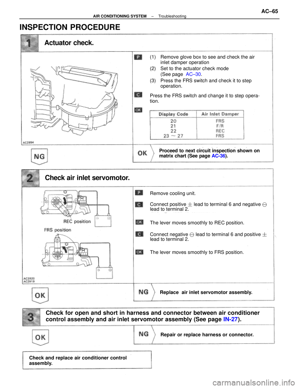
Actuator check.
Proceed to next circuit inspection shown on
matrix chart (See page AC-36).
Check air inlet servomotor.
Remove cooling unit.
Connect positive � lead to terminal 6 and negative �
lead to terminal 2.
The lever moves smoothly to REC position.
Connect negative � lead to terminal 6 and positive �
lead to terminal 2.
The lever moves smoothly to FRS position.
Replace air inlet servomotor assembly.
Check for open and short in harness and connector between air conditioner
control assembly and air inlet servomotor assembly (See page IN-27).
Repair or replace harness or connector.
Check and replace air conditioner control
assembly.
(1) Remove glove box to see and check the air
inlet damper operation
(2) Set to the actuator check mode (See page AC±30.
(3) Press the FRS switch and check it to step operation.
Press the FRS switch and change it to step opera-
tion.
INSPECTION PROCEDURE
±
AIR CONDITIONING SYSTEM TroubleshootingAC±65
WhereEverybodyKnowsYourName
Page 159 of 4087
EVAPORATOR
REMOVAL OF EVAPORATOR
1. DISCONNECT NEGATIVE (±) CABLE FROM BATTERY
2. RECOVER REFRIGERANT IN REFRIGERATION SYSTEMSee page AC±16
3. REMOVE ABS ACTUATOR
See page BR±48
4. REMOVE LIQUID TUBE AND SUCTION TUBE Remove two bolts and both tubes.
5. REMOVE EQUALIZER TUBE FROM EPR
Remove the bole and the tube.
NOTICE: Cap the open fittings immediately to keep mois-
ture out of the system.
6. REMOVE UNDER COVER GLOVE BOX AND SIDE AIR DUCT
7. DISCONNECT CONNECTORS AND REMOVE POWER STEERING RELAY BOX COOLING FAN COMPUTER AND
TRC COMPUTER
AC±122
±
AIR CONDITIONING SYSTEM Evaporator
WhereEverybodyKnowsYourName
Page 166 of 4087
BLOWER MOTOR
REMOVAL OF BLOWER MOTOR
1. REMOVE GLOVE BOXSee page BO±112
2. REMOVE ECU COVER
(a) Lift up the front end of the carpet on the passenger side.
(b) Remove the two nuts and the cover.
3. REMOVE CONNECTOR BRACKET Remove the two screws and the bracket.
4. REMOVE MOTOR (a) Disconnect the connector.
(b) Remove the three screws and the motor.
INSPECTION OF BLOWER MOTOR
See page AC±81
INSTALLATION OF BLOWER MOTOR
1. INSTALL MOTOR
(a) Install the motor with three screws.
(b) Connect the connector.
2. INSTALL CONNECTOR BRACKET
3. INSTALL ECU COVER
4. INSTALL GLOVE BOX
±
AIR CONDITIONING SYSTEM Blower MotorAC±129
WhereEverybodyKnowsYourName
Page 169 of 4087
BLOWER RESISTOR
REMOVAL OF BLOWER RESISTOR
1. REMOVE GLOVE BOXSee page BO±112
2. REMOVE RESISTOR
(a) Disconnect the connector.
(b) Remove the two screws and the resistor.
INSPECTION OF BLOWER RESISTOR
See page AC±80
INSTALLATION OF BLOWER RESISTOR
1. INSTALL RESISTOR
(a) Install the resistor with two screws.
(b) Connect the connector.
2. INSTALL GLOVE BOX
See page BO±112
ROOM TEMPERATURE SENSOR
REMOVAL OF ROOM TEMPERATURE
SENSOR
1. REMOVE NO. 1 LOWER FINISH PANEL
See page BO±112
2. REMOVE SENSOR Remove the screw and the sensor.
INSPECTION OF ROOM TEMPERATURE
SENSOR
See page AC±44
INSTALLATION OF ROOM
TEMPERATURE SENSOR
1. INSTALL SENSOR
Install the sensor with one screw.
2. INSTALL NO. 1 LOWER FINISH PANEL
See page BO±112
AC±132
±
AIR CONDITIONING SYSTEM Blower Resistor, Room Temperature Sensor
WhereEverybodyKnowsYourName
Page 174 of 4087
 Install the pressure switch to the liquid tube.
Specified torque: 10 NVm (100 kgf Vcm, 7 ft Vlbf)
HINT: Lock the switch mount on the t")
INSTALLATION OF PRESSURE SWITCH
1. INSTALL PRESSURE SWITCH
(a) Install the pressure switch to the liquid tube.
Specified torque: 10 NVm (100 kgf Vcm, 7 ft Vlbf)
HINT: Lock the switch mount on the tube with an open end
wrench, being careful not to deform the tube, and install the
switch.
(b) Connect the connector.
2. EVACUATE AIR IN REFRIGERATION SYSTEM AND CHARGE WITH REFRIGERANT
See page AC±17
Specified amount: 950 + 50 g (33.44 + 1.76 oz)
3. INSPECTION FOR LEAKAGE OF REFRIGERANT
Using a gas lead tester, check for leakage of refrigerant from
the pressure switch mount.
4. INSPECT A/C OPERATION
POWER TRANSISTOR
REMOVAL OF POWER TRANSISTOR
1. REMOVE GLOVE BOX
2. REMOVE POWER TRANSISTOR
(a) Disconnect connectors.
(b) Remove the two screws and the power transistor.
INSPECTION OF POWER TRANSISTOR
See page AC±79
INSTALLATION OF POWER
TRANSISTOR
1. INSTALL POWER TRANSISTOR
(a) Install power transistor with two screws.
(b) Connect connectors.
2. INSTALL GLOVE BOX
See page BO±112
±
AIR CONDITIONING SYSTEM Pressure Switch, Power TransistorAC±137
WhereEverybodyKnowsYourName
Page 175 of 4087
 Install the pressure switch to the liquid tube.
Specified torque: 10 NVm (100 kgf Vcm, 7 ft Vlbf)
HINT: Lock the switch mount on the t")
INSTALLATION OF PRESSURE SWITCH
1. INSTALL PRESSURE SWITCH
(a) Install the pressure switch to the liquid tube.
Specified torque: 10 NVm (100 kgf Vcm, 7 ft Vlbf)
HINT: Lock the switch mount on the tube with an open end
wrench, being careful not to deform the tube, and install the
switch.
(b) Connect the connector.
2. EVACUATE AIR IN REFRIGERATION SYSTEM AND CHARGE WITH REFRIGERANT
See page AC±17
Specified amount: 950 + 50 g (33.44 + 1.76 oz)
3. INSPECTION FOR LEAKAGE OF REFRIGERANT
Using a gas lead tester, check for leakage of refrigerant from
the pressure switch mount.
4. INSPECT A/C OPERATION
POWER TRANSISTOR
REMOVAL OF POWER TRANSISTOR
1. REMOVE GLOVE BOX
2. REMOVE POWER TRANSISTOR
(a) Disconnect connectors.
(b) Remove the two screws and the power transistor.
INSPECTION OF POWER TRANSISTOR
See page AC±79
INSTALLATION OF POWER
TRANSISTOR
1. INSTALL POWER TRANSISTOR
(a) Install power transistor with two screws.
(b) Connect connectors.
2. INSTALL GLOVE BOX
See page BO±112
±
AIR CONDITIONING SYSTEM Pressure Switch, Power TransistorAC±137
WhereEverybodyKnowsYourName
Page 466 of 4087
10. REMOVE RADIO WITH A/C CONTROL ASSEMBLY(a) Remove six bolts and the radio.
(b) Disconnect the connectors.
11. REMOVE NO. 2 UNDER COVER (a) Using a clip remover, remove two clips.
(b) Remove the cover.
12. REMOVE NO. 2 LOWER FINISH PANEL AND GLOVE COMPARTMENT ASSEMBLY
(a) Remove two caps and two screws.
(b) Remove two screws.
(c) Remove the glove compartment assembly.
13. REMOVE NO. 1 UNDER COVER (a) Remove three screws.
(b) Using the screwdriver, remove the cover.
14. REMOVE CONSOLE BOX Remove five screws, three bolts and the box.
±
BODY Instrument PanelBO±111
WhereEverybodyKnowsYourName
Page 873 of 4087

REMOVAL AND INSTALLATION OF
GLOVE BOX LIGHT SWITCH
1. REMOVE GLOVE BOX LIGHT SWITCH(a) Remove glove compartment.
(See page BO±112)
(b) Release two tabs and remove switch")
(GLOVE BOX LIGHT SWITCH)
REMOVAL AND INSTALLATION OF
GLOVE BOX LIGHT SWITCH
1. REMOVE GLOVE BOX LIGHT SWITCH(a) Remove glove compartment.
(See page BO±112)
(b) Release two tabs and remove switch.
2. INSTALL GLOVE BOX LIGHT SWITCH For installation, follow the removal procedure in reverse.
INSPECTION OF GLOVE BOX LIGHT
SWITCH
INSPECT GLOVE BOX LIGHT SWITCH
(Continuity)
Inspect the switch continuity between terminals.
If continuity is not as specified, replace the switch.
(Switch Circuit)
Disconnect the connector from the switch and inspect the
connector on the wire harness side as shown.
Check forTester connectionConditionSpecified value
Continuity2±GroundConstantContinuity
Voltage1±GroundLight control switch posi-OFFNo voltageVoltage1±Groundg
tionTAIL or HEADBattery positive voltage
If the circuit is not as specified, refer to BE±76 wiring diagram
and inspect the circuits connected to other parts.
(INTEGRATION RELAY)
(See page BE±49 )
(TAILLIGHT CONTROL RELAY)
(See page BE±57 )
BE±74
±
BODY ELECTRICAL SYSTEM Lighting System
WhereEverybodyKnowsYourName
 CABLE FROM BATTERY
2. RECOVER REFRIGERANT IN REFRIGERATION SYSTEMSee page AC±16
3. REMOVE ABS ACTUATOR
See page BR±48
4. REMOVE LI")
 Lift up the front end of the carpet on the passenger side.
(b) Remove the two nuts and the cover.")
 Disconnect the connector.
(b) Remove the two screws and the resistor.
INSPECTION OF BLOWER RE")
 Remove six bolts and the radio.
(b) Disconnect the connectors.
11. REMOVE NO. 2 UNDER COVER (a) Using a clip remover, remove two clips.
(b) Remove")