Page 145 of 4087
12. REMOVE CONNECTOR BRACKET FROM UNDER SIDEOF BLOWER MOTOR
Remove the two screws and the bracket.
13. REMOVE A/C UNIT
(a) Disconnect connectors from the unit.
(b) Remove the six bolts and the A/C unit.
INSTALLATION OF A/C UNIT
1. INSTALL A/C UNIT
(a) Match the standard holes of the A/C unit with those on the vehicle.
HINT:
wV
Pull the drain hose of the A/C unit forward until the
yellow paint on the hose is visible in the engine
compartment.
w V
Insert the drain hose into the engine compartment hose
until the match marks are aligned.
(b) Tighten six bolts.
2. INSTALL CONNECTOR BRACKET
3. INSTALL HEATER TO RESISTER NO. 3 DUCT
4. INSTALL REAR AIR DUCTS
5. INSTALL FLOOR CARPET
6. INSTALL INSULATOR RETAINER
7. INSTALL WATER HOSE TO HEATER RADIATOR
8. INSTALL BRAKE TUBE BRACKET MOUNTING BOLTS
9. INSTALL WATER VALVE See page AC±127
AC±108
±
AIR CONDITIONING SYSTEM Troubleshooting
WhereEverybodyKnowsYourName
Page 382 of 4087
VALVE BODY
VALVE BODY REMOVAL
AT0GG±02
1. DRAIN ATF
2. REMOVE FRONT EXHAUST PIPE(See pages EG±204)
3. REMOVE OIL PAN
(a) Remove the 19 bolts.
(b) Install the blade of SST between the transmission case and oil pan, cut off applied sealer.
SST 09032±00100
NOTICE: Be careful not to damage the oil pan flange.
4. EXAMINE PARTICLES IN PANRemove the magnets and use them to collect steel particles.
Carefully look at the foreign matter and particles in the pan
and on the magnets to anticipate the type of wear you will find
in the transmission:
Steel (magnetic) 0 bearing, gear and clutch plate wear
Brass (non±magnetic) 0 bushing wear
5. REMOVE OIL STRAINER Remove the 3 bolts holding the oil strainer to the valve body.
6. REMOVE SOLENOID WIRING
(a) Remove the 2 bolts and the clamp.
(b) Disconnect the 4 connectors from the solenoid valves.
±
A304E (1UZ±FE) AUTOMATIC TRANSMISSION VALVE BODYAT±19
WhereEverybodyKnowsYourName
Page 445 of 4087

REMOVAL OF SLIDING ROOF HOUSING
(See pages BO±85 to 87)
1. REMOVE FOLLOWING PARTS: (a) Interior light (See step 2 on page BO±85)
(b) Front pillar garnish (See step 2 on page BO±122)
(c) Rear seat cushion, rear seat back (See steps 1 to 2 on page BO±66)
(d) Roof side inner garnish (See step 8 on page BO±123)
(e) Center visor (See step 4 on page BO±122)
(f) Shoulder belt anchor (See step 7 on page BO±122)
(g) Sun visor (See step 3 on page BO±122)
(h) Sliding roof garnishes (See step 4 on page BO±85)
(i) Roof headlining (See step 2 on page BO±120)
(j) Sliding roof glass (See step 5 on page BO±85)
(k) Quarter trim (See step 7 on page BO±122)
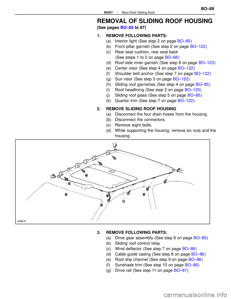
2. REMOVE SLIDING ROOF HOUSING (a) Disconnect the four drain hoses from the housing.
(b) Disconnect the connectors.
(c) Remove eight bolts.
(d) While supporting the housing, remove six nuts and thehousing.
3. REMOVE FOLLOWING PARTS: (a) Drive gear assembly (See step 6 on page BO±85)
(b) Sliding roof control relay
(c) Wind deflector (See step 7 on page BO±86)
(d) Cable guide casing (See step 8 on page BO±86)
(e) Roof drip channel (See step 9 on page BO±86)
(f) Sunshade trim (See step 10 on page BO±86)
(g) Drive rail (See step 11 on page BO±87)
±
BODY Moon Roof (Sliding Roof)BO±89
WhereEverybodyKnowsYourName
Page 1000 of 4087

(c) Install the new pad support plates.
8. INSTALL NEW PADS
(a) Apply disc brake grease to both sides of the inner anti±squeal
shim.
(b) Install the 2 anti±squeal shims on each pad.
(c) Install inner pad with the pad wear indicator plates facing downward.
(d) Install the outer pad.
NOTICE: There should be no oil or grease adhering to the fric-
tion surfaces of the pads or the disc.
(e) Install the 2 anti±squeal springs.
9. INSTALL CALIPER
(a) Draw out a small amount of brake fluid from the reservoir.
(b) P re ss in th e pisto n with wa te r pu mp plie rs or simila r
implement.
HINT: If the piston is difficult to push in, loosen the bleeder
plug and push in the piston while letting some brake fluid es-
cape.
(c) Install the caliper.
(d) Hold the sliding pin and torque the installation bolt.
Torque: 34 N Vm (350 kgf Vcm, 25 ft Vlbf)
10. INSTALL FRONT WHEEL
11. CHECK THAT FLUID LEVEL IS AT MAX LINE
CALIPER REMOVAL
BR042±0C
1. DISCONNECT FLEXIBLE HOSE
(a) Remove the union bolt and 2 gaskets from the caliper, then
disconnect the flexible hose from the caliper.
(b) Use a container to catch the brake fluid as it drains out.
±
BRAKE SYSTEM FRONT BRAKE (SC400)BR±31
WhereEverybodyKnowsYourName
Page 1008 of 4087

8. INSTALL NEW PADS
(a) Apply disc brake grease to both sides of the inner anti±squeal
shim.
(b) Install the 2 anti±squeal shims on each pad.
(c) Install the inner pad with the pad wear indicator plates facing
downward.
(d) Install the outer pad.
NOTICE: There should be no oil or grease adhering to the fric-
tion surfaces of the pads or the disc.
(e) Install the 2 anti±squeal springs.
9. INSTALL CALIPER
(a) Draw out a small amount of brake fluid from the reservoir.
(b) P re ss in th e pisto n with wa te r pu mp plie rs or simila r implement.
HINT: If the piston is difficult to push in, loosen the bleeder
plug and push in the piston while letting some brake fluid es-
cape.
(c) Install the caliper.
(d) Hold the sliding pin and torque the installation bolt.
Torque: 34 N Vm (350 kgf Vcm, 25 ft Vlbf)
10. INSTALL REAR WHEEL
11. CHECK THAT FLUID LEVEL IS AT MAX LINE
CALIPER REMOVAL
BR0EN±04
1. DISCONNECT FLEXIBLE HOSE
(a) Remove the union bolt and 2 gaskets from the caliper, then
disconnect the flexible hose from the caliper.
(b) Use a container to catch the brake fluid as it drains out.
2. REMOVE CALIPER
(a) Hold the sliding pin and loosen the 2 installation bolts.
(b) Remove the 2 installation bolts.
(c) Remove the caliper from the torque plate.
±
BRAKE SYSTEM REAR BRAKE (Disc Brake)BR±39
WhereEverybodyKnowsYourName
Page 1032 of 4087

MAIN POINT OF REMOVAL AND
INSTALLATION
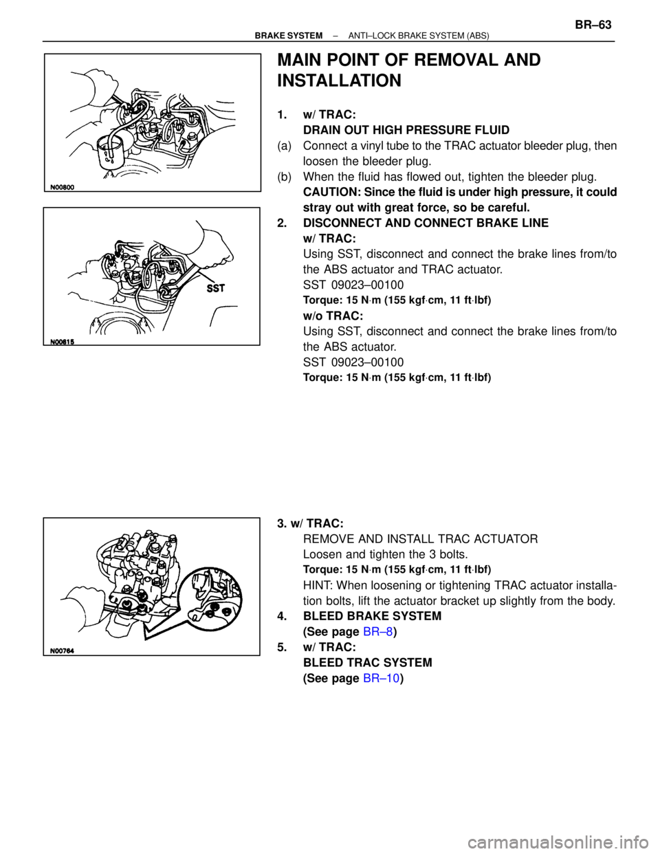
1. w/ TRAC:DRAIN OUT HIGH PRESSURE FLUID
(a) Connect a vinyl t ube to the TRAC actuator bleeder plug, then
loosen the bleeder plug.
(b) When the fluid has flowed out, tighten the bleeder plug. CAUTION: Since the fluid is under high pressure, it could
stray out with great force, so be careful.
2. DISCONNECT AND CONNECT BRAKE LINE w/ TRAC:
Using SST, disconnect and connect the brake lines from/to
the ABS actuator and TRAC actuator.
SST 09023±00100
Torque: 15 N Vm (155 kgf Vcm, 11 ft Vlbf)
w/o TRAC:
Using SST, disconnect and connect the brake lines from/to
the ABS actuator.
SST 09023±00100
Torque: 15 N Vm (155 kgf Vcm, 11 ft Vlbf)
3. w/ TRAC:
REMOVE AND INSTALL TRAC ACTUATOR
Loosen and tighten the 3 bolts.
Torque: 15 N Vm (155 kgf Vcm, 11 ft Vlbf)
HINT: When loosening or tightening TRAC actuator installa-
tion bolts, lift the actuator bracket up slightly from the body.
4. BLEED BRAKE SYSTEM
(See page BR±8)
5. w/ TRAC: BLEED TRAC SYSTEM
(See page BR±10)
±
BRAKE SYSTEM ANTI±LOCK BRAKE SYSTEM (ABS)BR±63
WhereEverybodyKnowsYourName
Page 1277 of 4087
REMOVAL OF RADIATOR
(See Components on page CO±15)
1. REMOVE BATTERY CAUTION: Work must be started after approx. 20 seconds or
longer from the time the ignition switch is turned to the
ºLOCKº position and the negative (±) terminal cable is dis-
connected from the battery.
2. REMOVE ENGINE UNDER COVERS
3. DRAIN ENGINE COOLANT (See page CO±6)
4. REMOVE RADIATOR RESERVOIR TANK (a) Disconnect the coolant level sensor connector.
(b) Disconnect the following hoses:(1) Reservoir hose from water inlet housing
(2) Reservoir hose from radiator
(c) Remove the two bolts and reservoir tank bracket.
(d) Disconnect the reservoir tank from the reservoir tank bracket, and remove the reservoir tank.
5. DISCONNECT HOSES Disconnect the following hoses:(1) Upper radiator hose from radiator
(2) Lower radiator hose from radiator
(3) Two oil cooler hoses (for A/T) from radiator. Plug hose end.
CO±16
±
COOLIING SYSTEM Radiator
WhereEverybodyKnowsYourName
Page 1289 of 4087

REMOVAL OF HYDRAULIC PUMP
(See Components on page CO±26)
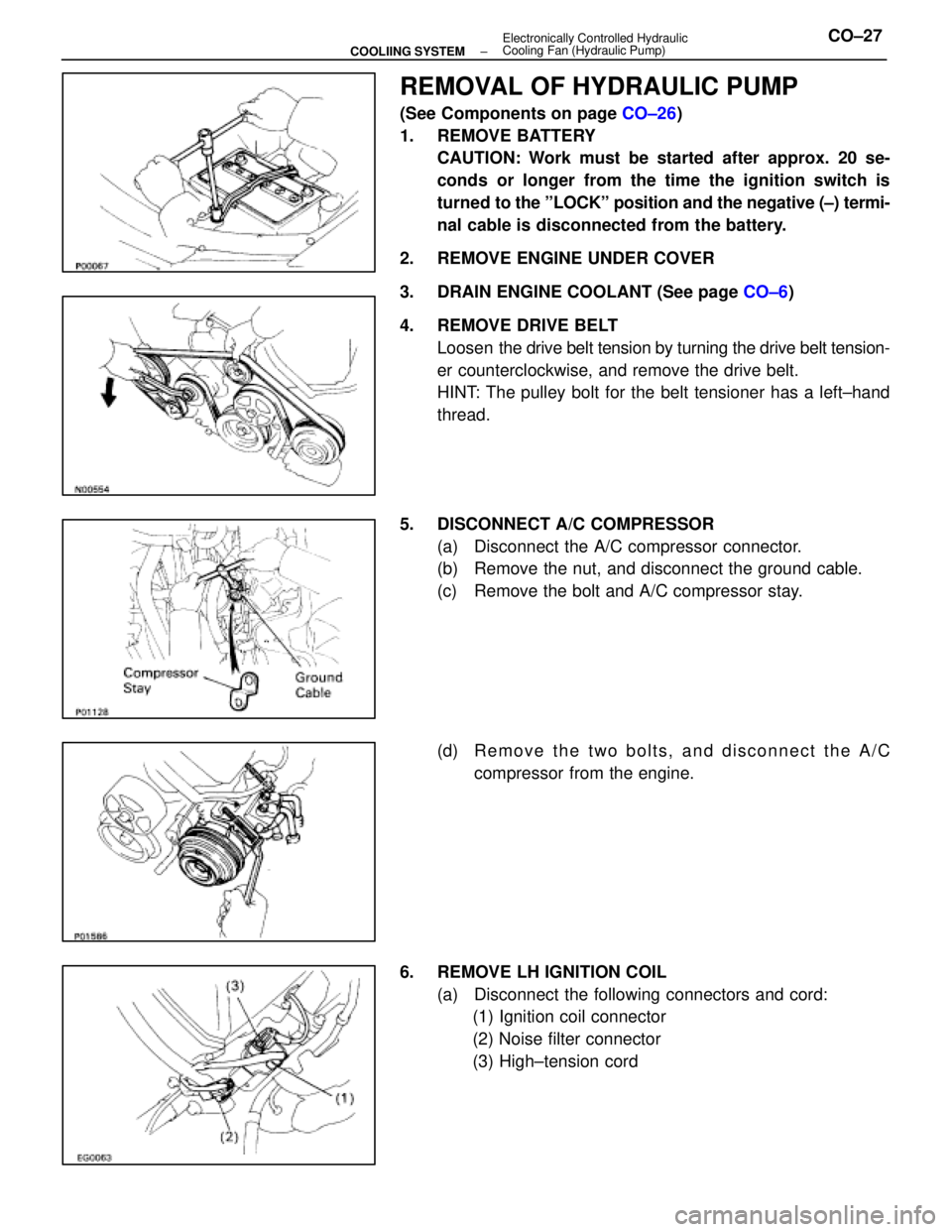
1. REMOVE BATTERY CAUTION: Work must be started after approx. 20 se-
conds or longer from the time the ignition switch is
turned to the ºLOCKº position and the negative (±) termi-
nal cable is disconnected from the battery.
2. REMOVE ENGINE UNDER COVER
3. DRAIN ENGINE COOLANT (See page CO±6)
4. REMOVE DRIVE BELT Loosen the drive belt tension by turning the drive belt tension-
er counterclockwise, and remove the drive belt.
HINT: The pulley bolt for the belt tensioner has a left±hand
thread.
5. DISCONNECT A/C COMPRESSOR (a) Disconnect the A/C compressor connector.
(b) Remove the nut, and disconnect the ground cable.
(c) Remove the bolt and A/C compressor stay.
(d) R e m o v e t h e t w o b o l t s , a n d d i s c onnect the A/C
compressor from the engine.
6. REMOVE LH IGNITION COIL (a) Disconnect the following connectors and cord:(1) Ignition coil connector
(2) Noise filter connector
(3) High±tension cord
±
COOLIING SYSTEM Electronically Controlled Hydraulic
Cooling Fan (Hydraulic Pump)CO±27
WhereEverybodyKnowsYourName