Page 2802 of 4087
REMOVAL OF RADIATOR
(See Components on page CO±15)
1. REMOVE BATTERY CAUTION: Work must be started after approx. 20 seconds or
longer from the time the ignition switch is turned to the
ºLOCKº position and the negative (±) terminal cable is dis-
connected from the battery.
2. REMOVE ENGINE UNDER COVERS
3. DRAIN ENGINE COOLANT (See page CO±6)
4. REMOVE RADIATOR RESERVOIR TANK (a) Disconnect the coolant level sensor connector.
(b) Disconnect the following hoses:(1) Reservoir hose from water inlet housing
(2) Reservoir hose from radiator
(c) Remove the two bolts and reservoir tank bracket.
(d) Disconnect the reservoir tank from the reservoir tank bracket, and remove the reservoir tank.
5. DISCONNECT HOSES Disconnect the following hoses:(1) Upper radiator hose from radiator
(2) Lower radiator hose from radiator
(3) Two oil cooler hoses (for A/T) from radiator. Plug hose end.
CO±16
±
COOLIING SYSTEM Radiator
WhereEverybodyKnowsYourName
Page 2813 of 4087

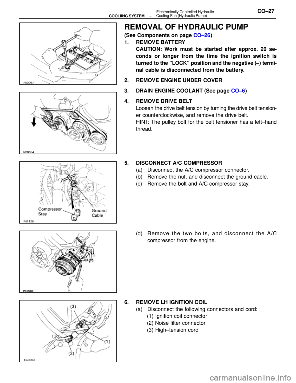
REMOVAL OF HYDRAULIC PUMP
(See Components on page CO±26)
1. REMOVE BATTERY CAUTION: Work must be started after approx. 20 se-
conds or longer from the time the ignition switch is
turned to the ºLOCKº position and the negative (±) termi-
nal cable is disconnected from the battery.
2. REMOVE ENGINE UNDER COVER
3. DRAIN ENGINE COOLANT (See page CO±6)
4. REMOVE DRIVE BELT Loosen the drive belt tension by turning the drive belt tension-
er counterclockwise, and remove the drive belt.
HINT: The pulley bolt for the belt tensioner has a left±hand
thread.
5. DISCONNECT A/C COMPRESSOR (a) Disconnect the A/C compressor connector.
(b) Remove the nut, and disconnect the ground cable.
(c) Remove the bolt and A/C compressor stay.
(d) R e m o v e t h e t w o b o l t s , a n d d i s c onnect the A/C
compressor from the engine.
6. REMOVE LH IGNITION COIL (a) Disconnect the following connectors and cord:(1) Ignition coil connector
(2) Noise filter connector
(3) High±tension cord
±
COOLIING SYSTEM Electronically Controlled Hydraulic
Cooling Fan (Hydraulic Pump)CO±27
WhereEverybodyKnowsYourName
Page 2834 of 4087
REMOVAL OF HYDRAULIC MOTOR
(See Components on page CO±47)
1. REMOVE BATTERY CAUTION: Work must be started after approx. 20 se-
conds or longer from the time the ignition switch is
turned to the ºLOCKº position and the negative (±) termi-
nal cable is disconnected from the battery.
2. REMOVE ENGINE UNDER COVERS
3. DRAIN ENGINE COOLANT (See page CO±6)
4. REMOVE RADIATOR RESERVOIR TANK (a) Disconnect the coolant level sensor connector.
(b) Disconnect the following hoses:(1) Reservoir hose from water inlet housing
(2) Reservoir hose from radiator
(c) Remove the two bolts and reservoir tank bracket.
(d) Disconnect the reservoir tank from the reservoir tank bracket, and remove the reservoir tank.
5. DISCONNECT HOSES Disconnect the following hoses:(1) Upper radiator hose from radiator
(2) Pressure hose from hydraulic motor
(3) Return hose from hydraulic motor
CO±48
±
COOLIING SYSTEM Electronically Controlled Hydraulic Cooling Fan
(Hydraulic Motor)
WhereEverybodyKnowsYourName
Page 2896 of 4087

REMOVAL OF STARTER
(See Components on page ST±5)
1. DISCONNECT CABLE FROM NEGATIVE TERMINAL OF BATTERY
CAUTION: Work must be started after approx. 20 se-
conds or longer from the time the ignition switch is
turned to the ºLOCKº position and the negative (±) termi-
nal cable is disconnected from the battery.
2. DRAIN ENGINE COOLANT
3. REMOVE THROTTLE BODY COVER (a) Remove the mounting cap nut.
(b) Loosen the two bolts, and remove the throttle bodycover.
4. DISCONNECT CONTROL CABLES FROM THROTTLE BODY
Disconnect the following cables:(1) Accelerator cable
(2) A/T throttle control cable
(3) (w/ Cruise Control System) Cruise control actuator cable
5. REMOVE INTAKE AIR CONNECTOR (a) Disconnect the following hoses:(1) Air hose from ISC valve
(2) Air hose (from PS air control valve) from intake air
connector
(b) Remove the bolt holding the intake air connector to the cylinder head cover.
(c) Loosen the two hose clamps.
(d) Disconnect the intake air connector from the throttle
body and air cleaner hose, and remove the intake air
connector.
ST±6
±
STARTING SYSTEM Starter
WhereEverybodyKnowsYourName
Page 3215 of 4087
DIFFERENTIAL REMOVAL
SA0S6±05
1. REMOVE PROPELLER SHAFT(See page PR±6 or 24)
2. DRAIN DIFFERENTIAL OIL
3. DISCONNECT REAR DRIVE SHAFTS
(a) Place matchmarks on the drive shafts and side gear shafts.
(b) Using a hexagon wrench, disconnect the drive shafts from
the differential.
(c) Hang up the drive shafts using wire, etc.
4. REMOVE DIFFERENTIAL
(a) Support the differential with a jack.
(b) Using a hexagon wrench, remove the 3 bolts.
(c) Remove the 2 bolts and lower stoppers.
(d) Remove the differential.
SA±82
±
SUSPENSION AND AXLE REAR DIFFERENTIAL
WhereEverybodyKnowsYourName
Page 3342 of 4087
ON±VEHICLE REPAIR
COMPONENTS
SA097±02
SIDE GEAR SHAFT OIL SEAL
REPLACEMENT
SA0V1±04
1. DRAIN DIFFERENTIAL OIL
2. REMOVE REAR DRIVE SHAFT(See page SA±65)
3. REMOVE SIDE GEAR SHAFT
(a) Using SST and 2 bolts, remove the side gear shaft. SST 09520±22010
(b) Remove the snap ring from the side gear shaft.
4. REMOVE SIDE GEAR SHAFT OIL SEAL Using SST, remove the oil seal.
SST 09308±00010
±
SUSPENSION AND AXLE REAR DIFFERENTIALSA±79
WhereEverybodyKnowsYourName