Page 1708 of 4087
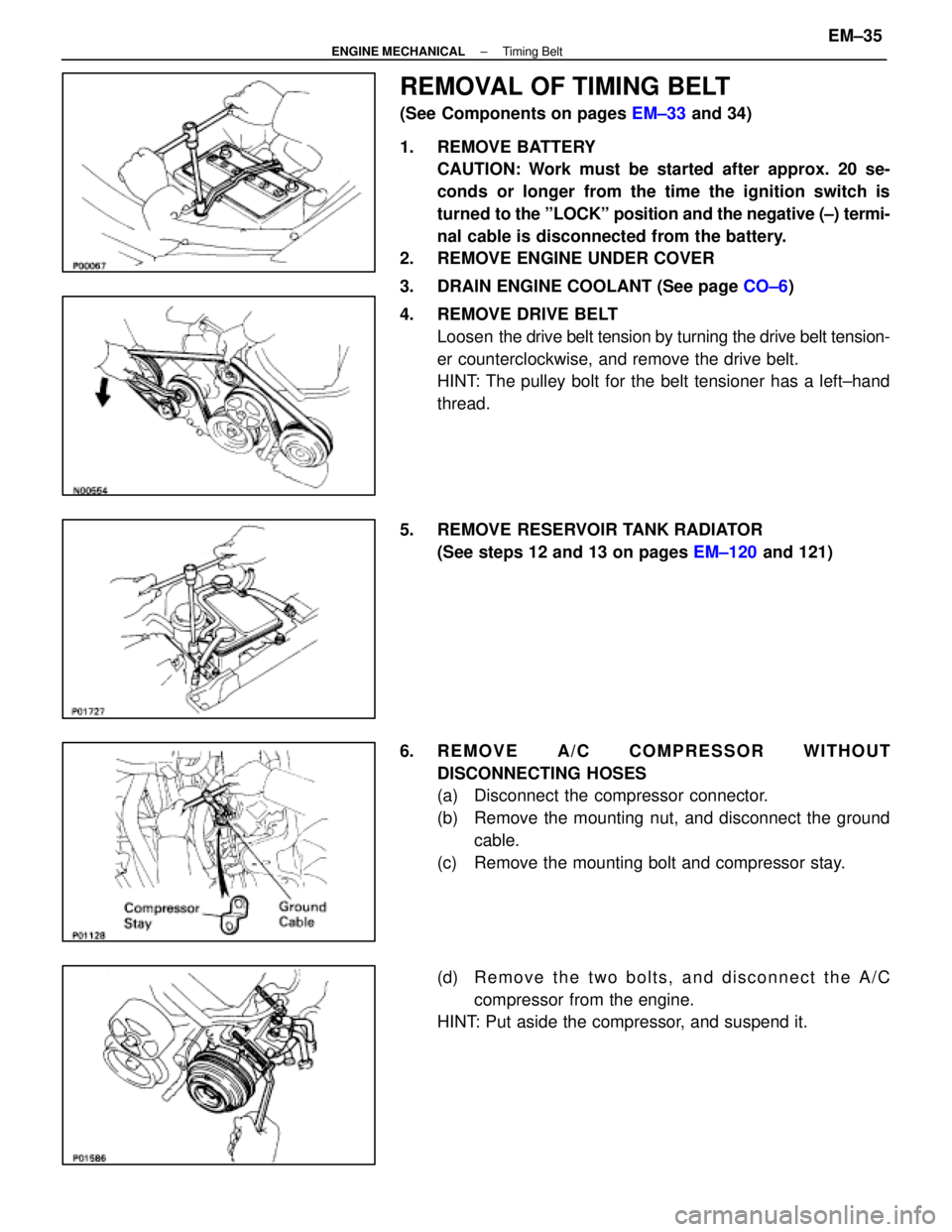
REMOVAL OF TIMING BELT
(See Components on pages EM±33 and 34)
1. REMOVE BATTERY CAUTION: Work must be started after approx. 20 se-
conds or longer from the time the ignition switch is
turned to the ºLOCKº position and the negative (±) termi-
nal cable is disconnected from the battery.
2. REMOVE ENGINE UNDER COVER
3. DRAIN ENGINE COOLANT (See page CO±6)
4. REMOVE DRIVE BELT Loosen the drive belt tension by turning the drive belt tension-
er counterclockwise, and remove the drive belt.
HINT: The pulley bolt for the belt tensioner has a left±hand
thread.
5. REMOVE RESERVOIR TANK RADIATOR (See steps 12 and 13 on pages EM±120 and 121)
6. REMOVE A/C COMPRESSOR WITHOUT DISCONNECTING HOSES
(a) Disconnect the compressor connector.
(b) Remove the mounting nut, and disconnect the groundcable.
(c) Remove the mounting bolt and compressor stay.
(d) R e m o v e t h e t w o b o l t s , a n d d i s c onnect the A/C
compressor from the engine.
HINT: Put aside the compressor, and suspend it.
±
ENGINE MECHANICAL Timing BeltEM±35
WhereEverybodyKnowsYourName
Page 1909 of 4087
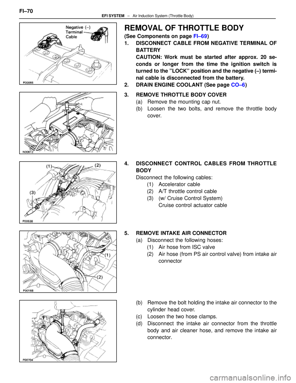
REMOVAL OF THROTTLE BODY
(See Components on page FI±69)
1. DISCONNECT CABLE FROM NEGATIVE TERMINAL OF BATTERY
CAUTION: Work must be started after approx. 20 se-
conds or longer from the time the ignition switch is
turned to the ºLOCKº position and the negative (±) termi-
nal cable is disconnected from the battery.
2. DRAIN ENGINE COOLANT (See page CO±6)
3. REMOVE THROTTLE BODY COVER (a) Remove the mounting cap nut.
(b) Loosen the two bolts, and remove the throttle bodycover.
4. DISCONNECT CONTROL CABLES FROM THROTTLE BODY
Disconnect the following cables:(1) Accelerator cable
(2) A/T throttle control cable
(3) (w/ Cruise Control System)
Cruise control actuator cable
5. REMOVE INTAKE AIR CONNECTOR (a) Disconnect the following hoses:(1) Air hose from ISC valve
(2) Air hose (from PS air control valve) from intake air connector
(b) Remove the bolt holding the intake air connector to the cylinder head cover.
(c) Loosen the two hose clamps.
(d) Disconnect the intake air connector from the throttle body and air cleaner hose, and remove the intake air
connector.
FI±70
EFI SYSTEM
± Air Induction System (Throttle Body)
WhereEverybodyKnowsYourName
Page 1958 of 4087
INSPECTION OF EGR GAS
TEMPERATURE SENSOR
1. DISCONNECT CABLE FROM NEGATIVE TERMINAL OFBATTERY
CAUTION: Work must be started after approx. 20 se-
conds or longer from the time the ignition switch is
turned to the ºLOCKº position and the negative (±) termi-
nal cable is disconnected from the battery.
2. DRAIN ENGINE COOLANT
3. REMOVE EGR VALVE (a) Disconnect the EGR gas temperature sensor.
(b) Disconnect the following hoses from the EGR valve:(1) Water by±pass hose (from ISC valve)
(2) Water by±pass hose (from rear water by±pass joint)
(c) Remove the two nuts, EGR valve and gasket.
4. REMOVE EGR VALVE ADAPTOR (a) Disconnect the EGR gas temperature sensor.
(b) Disconnect the PCV hose from the EGR valve adaptor.
(c) Remove the two bolts, two nuts, EGR valve adaptor andgasket. FI±103
EFI SYSTEM
± Electronic Control System (EGR Gas Temperature Sensor (USA Spec. only))
WhereEverybodyKnowsYourName
Page 2048 of 4087
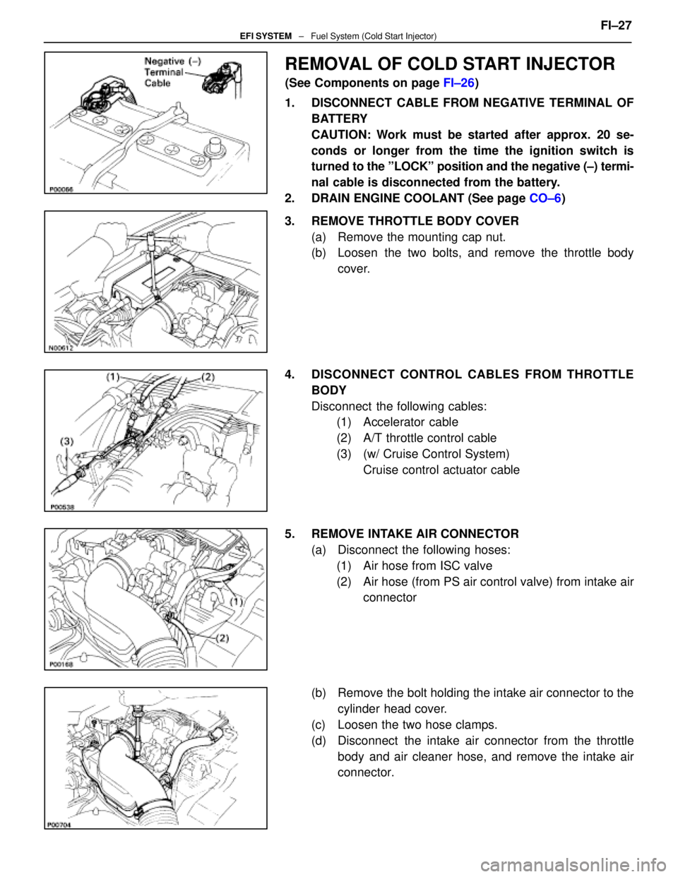
REMOVAL OF COLD START INJECTOR
(See Components on page FI±26)
1. DISCONNECT CABLE FROM NEGATIVE TERMINAL OF BATTERY
CAUTION: Work must be started after approx. 20 se-
conds or longer from the time the ignition switch is
turned to the ºLOCKº position and the negative (±) termi-
nal cable is disconnected from the battery.
2. DRAIN ENGINE COOLANT (See page CO±6)
3. REMOVE THROTTLE BODY COVER (a) Remove the mounting cap nut.
(b) Loosen the two bolts, and remove the throttle bodycover.
4. DISCONNECT CONTROL CABLES FROM THROTTLE BODY
Disconnect the following cables:(1) Accelerator cable
(2) A/T throttle control cable
(3) (w/ Cruise Control System)
Cruise control actuator cable
5. REMOVE INTAKE AIR CONNECTOR (a) Disconnect the following hoses:(1) Air hose from ISC valve
(2) Air hose (from PS air control valve) from intake air connector
(b) Remove the bolt holding the intake air connector to the cylinder head cover.
(c) Loosen the two hose clamps.
(d) Disconnect the intake air connector from the throttle body and air cleaner hose, and remove the intake air
connector. FI±27
EFI SYSTEM
± Fuel System (Cold Start Injector)
WhereEverybodyKnowsYourName
Page 2065 of 4087
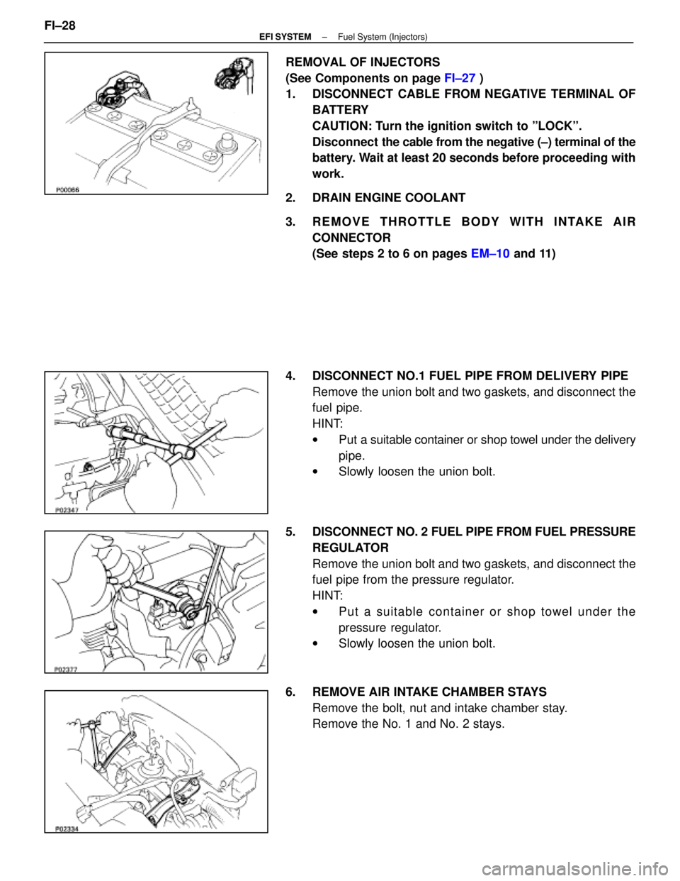
REMOVAL OF INJECTORS
(See Components on page FI±27 )
1. DISCONNECT CABLE FROM NEGATIVE TERMINAL OF
BATTERY
CAUTION: Turn the ignition switch to ºLOCKº.
Disconnect the cable from the negative (±) terminal of the
battery. Wait at least 20 seconds before proceeding with
work.
2. DRAIN ENGINE COOLANT
3. REMOVE THROTTLE BODY WITH INTAKE AIR CONNECTOR
(See steps 2 to 6 on pages EM±10 and 11)
4. DISCONNECT NO.1 FUEL PIPE FROM DELIVERY PIPE Remove the union bolt and two gaskets, and disconnect the
fuel pipe.
HINT:
wPut a suitable container or shop towel under the delivery
pipe.
w Slowly loosen the union bolt.
5. DISCONNECT NO. 2 FUEL PIPE FROM FUEL PRESSURE
REGULATOR
Remove the union bolt and two gaskets, and disconnect the
fuel pipe from the pressure regulator.
HINT:
w Put a suitable container or shop towel under the
pressure regulator.
w Slowly loosen the union bolt.
6. REMOVE AIR INTAKE CHAMBER STAYS Remove the bolt, nut and intake chamber stay.
Remove the No. 1 and No. 2 stays.
FI±28
±
EFI SYSTEM Fuel System (Injectors)
WhereEverybodyKnowsYourName
Page 2112 of 4087
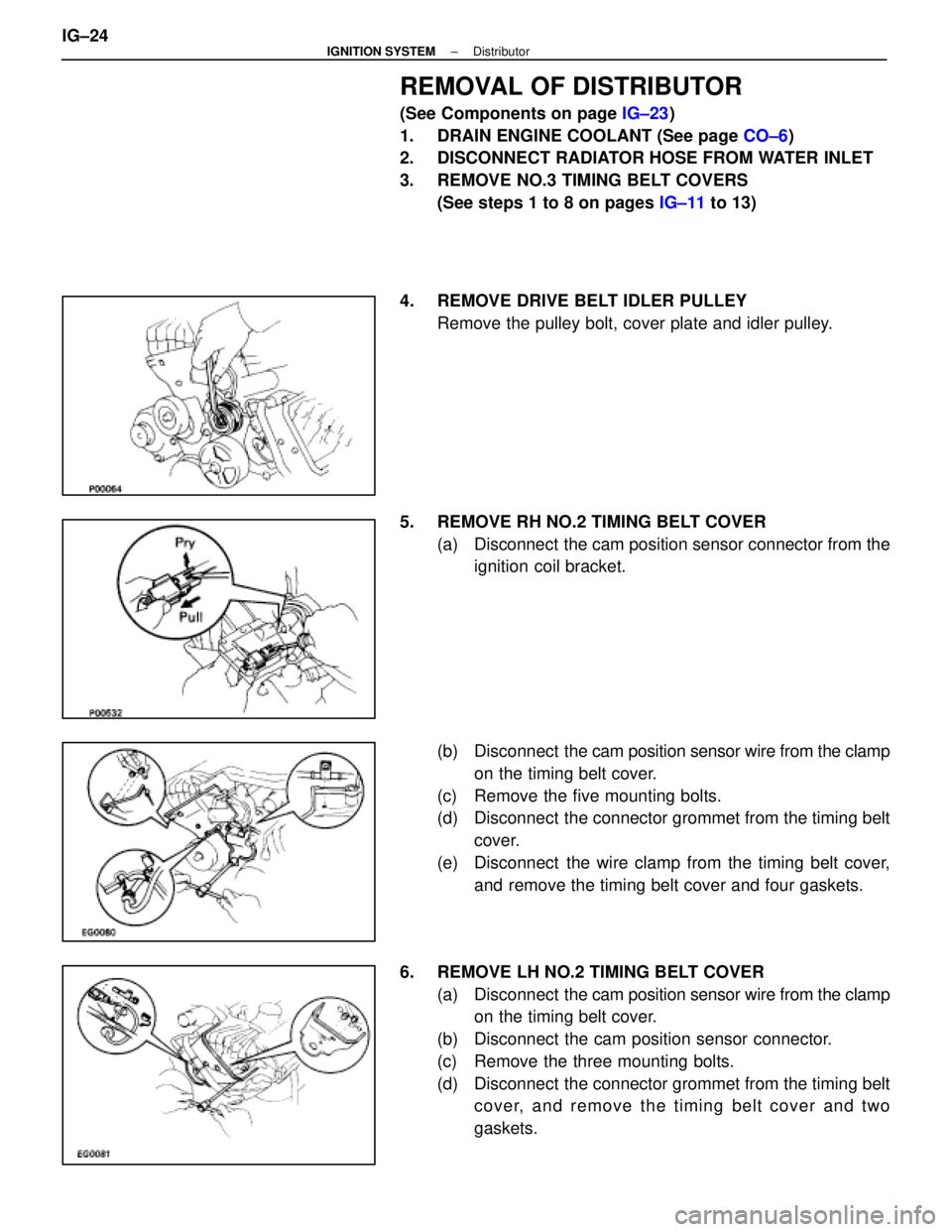
REMOVAL OF DISTRIBUTOR
(See Components on page IG±23)
1. DRAIN ENGINE COOLANT (See page CO±6)
2. DISCONNECT RADIATOR HOSE FROM WATER INLET
3. REMOVE NO.3 TIMING BELT COVERS
(See steps 1 to 8 on pages IG±11 to 13)
4. REMOVE DRIVE BELT IDLER PULLEY Remove the pulley bolt, cover plate and idler pulley.
5. REMOVE RH NO.2 TIMING BELT COVER (a) Disconnect the cam position sensor connector from theignition coil bracket.
(b) Disconnect the cam position sensor wire from the clamp
on the timing belt cover.
(c) Remove the five mounting bolts.
(d) Disconnect the connector grommet from the timing belt cover.
(e) Disconnect the wire clamp from the timing belt cover, and remove the timing belt cover and four gaskets.
6. REMOVE LH NO.2 TIMING BELT COVER (a) Disconnect the cam position sensor wire from the clamp
on the timing belt cover.
(b) Disconnect the cam position sensor connector.
(c) Remove the three mounting bolts.
(d) Disconnect the connector grommet from the timing belt cover, and remove the timing belt cover and two
gaskets.
IG±24
±
IGNITION SYSTEM Distributor
WhereEverybodyKnowsYourName
Page 2118 of 4087

SERVICE SPECIFICATIONS
SERVICE DATA
Oil pressureat idle speed29 kPa (0.3 kgf/cm, 4.3 psi) or more
at 3,000 rpm 294±539 kPa
(3.0±5.5 kgf/cm, 43±78 psi)
Oil pumpTip clearanceSTD0.310±0.490 mm0.0122±0.0193 in.
Limit 0.53 mm0.0209 in.
Body clearanceSTD 0.100±0.175 mm0.0039±0.0069 in.
Limit 0.20 mm0.0079 in.
Rotor clearanceSTD 0.030±0.090 mm0.0012±0.0035 in.
Limit0.12 mm0.0047 in.
TORQUE SPECIFICATIONS
Part tightenedN mkgf cmftVlbf
A/C compressor X Cylinder blockThrough bolt2626519
Bolt and nut 52530 38
Oil pressure switch X Cylinder
block14150 11
Oil drain plug X No.2 oil pan45450 33
Oil pump body cover X Oil pump
body10105 8
Plug X Oil pump body49500 36
Oil pump X Cylinder block21210 15
No.1 oil pan X Cylinder block12 mm head bolt21210 15
14 mm head bolt39400 29
Oil pan baffle plate X No.1 oil pan8.8 90 78 in.
Vlbf
Oil strainer X No.1 oil pan8.8 90 78 in. Vlbf
No.2 oil pan X No.1 oil pan8.8 90 78 in. Vlbf
Oil level sensor X No.1 oil pan5.4 5548 in. Vlbf
±
LUBRICATION SYSTEM Service SpecificationsLU±19
WhereEverybodyKnowsYourName
Page 2211 of 4087
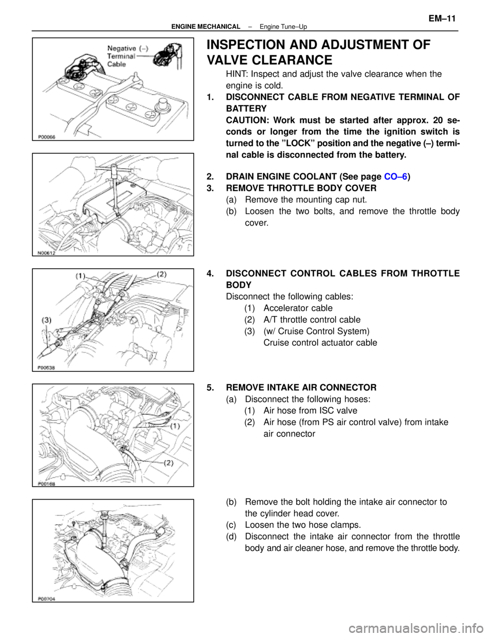
INSPECTION AND ADJUSTMENT OF
VALVE CLEARANCE
HINT: Inspect and adjust the valve clearance when the
engine is cold.
1. DISCONNECT CABLE FROM NEGATIVE TERMINAL OF BATTERY
CAUTION: Work must be started after approx. 20 se-
conds or longer from the time the ignition switch is
turned to the ºLOCKº position and the negative (±) termi-
nal cable is disconnected from the battery.
2. DRAIN ENGINE COOLANT (See page CO±6)
3. REMOVE THROTTLE BODY COVER (a) Remove the mounting cap nut.
(b) Loosen the two bolts, and remove the throttle body
cover.
4. DISCONNECT CONTROL CABLES FROM THROTTLE BODY
Disconnect the following cables:(1) Accelerator cable
(2) A/T throttle control cable
(3) (w/ Cruise Control System) Cruise control actuator cable
5. REMOVE INTAKE AIR CONNECTOR (a) Disconnect the following hoses:(1) Air hose from ISC valve
(2) Air hose (from PS air control valve) from intake
air connector
(b) Remove the bolt holding the intake air connector to the cylinder head cover.
(c) Loosen the two hose clamps.
(d) Disconnect the intake air connector from the throttle
body and air cleaner hose, and remove the throttle body.
±
ENGINE MECHANICAL Engine Tune±UpEM±11
WhereEverybodyKnowsYourName