Page 825 of 4087

(HEADLIGHT SYSTEM)
Description ± Headlight System
The component parts of this system and their function are described in the \
following table.
Parts NameFunction
Light Control SwitchGrounds current from the headlight control relay and taillight control r\
elay via the
integration relay, switching each relay and supplying current to the appropriate bulbs
accordance with the switch position.
Dimmer SwitchGrounds current from the dimmer relay in accordance with the switch posi\
tion, turning
on the ºLO±Beamº or ºHI Beamº lights. In the case of º\
FLASHº it turns the heading
control relay and turns on the ºHI Beamº lights.
Headlight Control
RelayTurned on by signals from the light control switch, dimmer switch and run\
ning light
relay and supplies current to each bulb or headlight dimmer relay.
Headlight
Dimmer RelayReceives current from the headlight control relay, which switches the relay according
to the position of the dimmer switch and sends current to the headlight \
ºLO±Beamº
or ºHI Beamº.
Integration RelayCarries out ºLight Auto Turn±offº of the headlights and taillights and cuts off current to
the light control switch in accordance with signals from the GAUGE fuse \
and courtesy
switch.
Door Courtesy
Switch/Driver 'sDetects when the door is open and sends the appropriate signals to integ\
ration relay.
(Light Auto Turn±Off System)
Parking Brake
Switch
(CANADA)Detects when the parking brake lever is released and sends the appropria\
te signals to
daytime running light relay.
±
BODY ELECTRICAL SYSTEM Lighting SystemBE±29
WhereEverybodyKnowsYourName
Page 826 of 4087
System Description ± Headlights
DAYTIME RUNNING LIGHT SYSTEM
The Daytime Running Light (DRL) system is activated when engine is started (However, if the parking brake
lever is engaged when the engine is started, the DRL will not light up a\
fter the engine has started. Once the
parking brake is released, the DRL will then light up and will remain on regardless of operation of\
the parking
brake lever).
The DRL remain on until the ignition switch is turned off.
BE±30±
BODY ELECTRICAL SYSTEM Lighting System
WhereEverybodyKnowsYourName
Page 832 of 4087
Connector Diagrams ± Headlights
BE±36±
BODY ELECTRICAL SYSTEM Lighting System
WhereEverybodyKnowsYourName
Page 834 of 4087

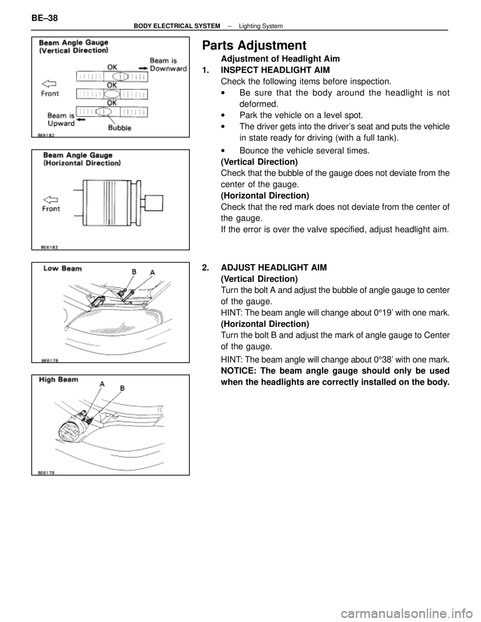
Parts Adjustment
Adjustment of Headlight Aim
1. INSPECT HEADLIGHT AIM Check the following items before inspection.
wBe sure that the body around the headlight is not
deformed.
w Park the vehicle on a level spot.
w The driver gets into the driver's seat and puts the vehicle
in state ready for driving (with a full tank).
w Bounce the vehicle several times.
(Vertical Direction)
Check that the bubble of the gauge does not deviate from the
center of the gauge.
(Horizontal Direction)
Check that the red mark does not deviate from the center of
the gauge.
If the error is over the valve specified, adjust headlight aim.
2. ADJUST HEADLIGHT AIM (Vertical Direction)
Turn the bolt A and adjust the bubble of angle gauge to center
of the gauge.
HINT: The beam angle will change about 0 519' with one mark.
(Horizontal Direction)
Turn the bolt B and adjust the mark of angle gauge to Center
of the gauge.
HINT: The beam angle will change about 0 538' with one mark.
NOTICE: The beam angle gauge should only be used
when the headlights are correctly installed on the body.
BE±38
±
BODY ELECTRICAL SYSTEM Lighting System
WhereEverybodyKnowsYourName
Page 852 of 4087

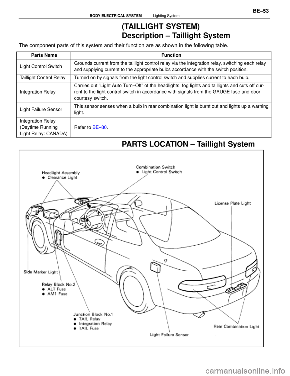
(TAILLIGHT SYSTEM)
Description ± Taillight System
The component parts of this system and their function are as shown in the f\
ollowing table.
�������� ��������Parts Name������������������\
����������� ������������������\
�����������Function
�������� �
�������
��������
Light Control Switch������������������\
����������� �
������������������\
����������
������������������\
�����������
Grounds current from the taillight control relay via the integration rel\
ay, switching each relay
and supplying current to the appropriate bulbs accordance with the switc\
h position.
�������� ��������Taillight Control Relay������������������\
����������� ������������������\
�����������Turned on by signals from the light control switch and supplies current t\
o each bulb.
�������� �
�������
�
�������
��������
Integration Relay
������������������\
����������� �
������������������\
����������
�
������������������\
����������
������������������\
�����������
Carries out ºLight Auto Turn±Offº of the headlights, fog lights and taillights and cuts off cur-
rent to the light control switch in accordance with signals from the GAU\
GE fuse and door
courtesy switch.
�������� �
�������
��������
Light Failure Sensor������������������\
����������� �
������������������\
����������
������������������\
�����������
This sensor senses when a bulb in rear combination light is burnt out an\
d lights up a warning
light.
��������Integration Relay������������������\
������������������� ��������Integration Relay
(Daytime Running
������������������\
����������� ������������������\
�����������
Refer to
BE±30.�������� ��������(y g
Light Relay: CANADA)������������������\
����������� ������������������\
�����������
PARTS LOCATION ± Taillight System
±
BODY ELECTRICAL SYSTEM Lighting SystemBE±53
WhereEverybodyKnowsYourName
Page 1140 of 4087
8. INSPECT CHARGING CIRCUIT WITH LOAD(a) With the engine running at 2,000 rpm, turn on the highbeam headlights and place the heater blower switch at
ºHIº.
(b) Check the reading on the ammeter.
Standard amperage: 30 A or more
If the ammeter reading is less than standard amperage, re-
pair the alternator. (See page CH±9)
HINT: With the battery fully charged, the indication will some-
times be less than standard amperage.
9. REINSTALL ENGINE UNDER COVER
CH±8
±
CHARGING SYSTEM On±Vehicle Inspection
WhereEverybodyKnowsYourName
Page 2772 of 4087
8. INSPECT CHARGING CIRCUIT WITH LOAD(a) With the engine running at 2,000 rpm, turn on the highbeam headlights and place the heater blower switch at
ºHIº.
(b) Check the reading on the ammeter.
Standard amperage: 30 A or more
If the ammeter reading is less than standard amperage, re-
pair the alternator. (See page CH±9)
HINT: With the battery fully charged, the indication will some-
times be less than standard amperage.
9. REINSTALL ENGINE UNDER COVER
CH±8
±
CHARGING SYSTEM On±Vehicle Inspection
WhereEverybodyKnowsYourName
Page 3170 of 4087

2HEAT METHOD: When the problem seems to occur when the suspect area is heate\
d.
Heat the component that is likely the cause of the mal-
function with a hair dryer or similar object. Check to see
if the malfunction will occur.
Notice:
�Do not heat to more than 60 �C (140 �F) (Tempera-
ture limit that the component can be touched with a
hand.)
� Do not apply heat directly to any part in the ECU.
3WATER SPRINKLING METHOD: When the malfunction seems to occur on a rainy day or in
a high±humidity condition.
Sprinkle water onto the vehicle and check to see if the
malfunction will occur.
Notice: Never apply water directly onto the
electronic components.
HINT:
�If the vehicle is subject to water leakage, the leaked
water may contaminate the ECU. When testing a ve-
hicle with a water leakage problem, special caution
must be paid.
4OTHER: When a malfunction seems to occur when electrical load is excessive.
Turn on all electrical loads including the heater blower,
headlights, rear window defogger, etc. and check to see
if the malfunction will occur.
RS±66±
SUPPLEMENTAL RESTRAINT SYSTEM TROUBLESHOOTING
WhereEverybodyKnowsYourName