Page 18 of 4087

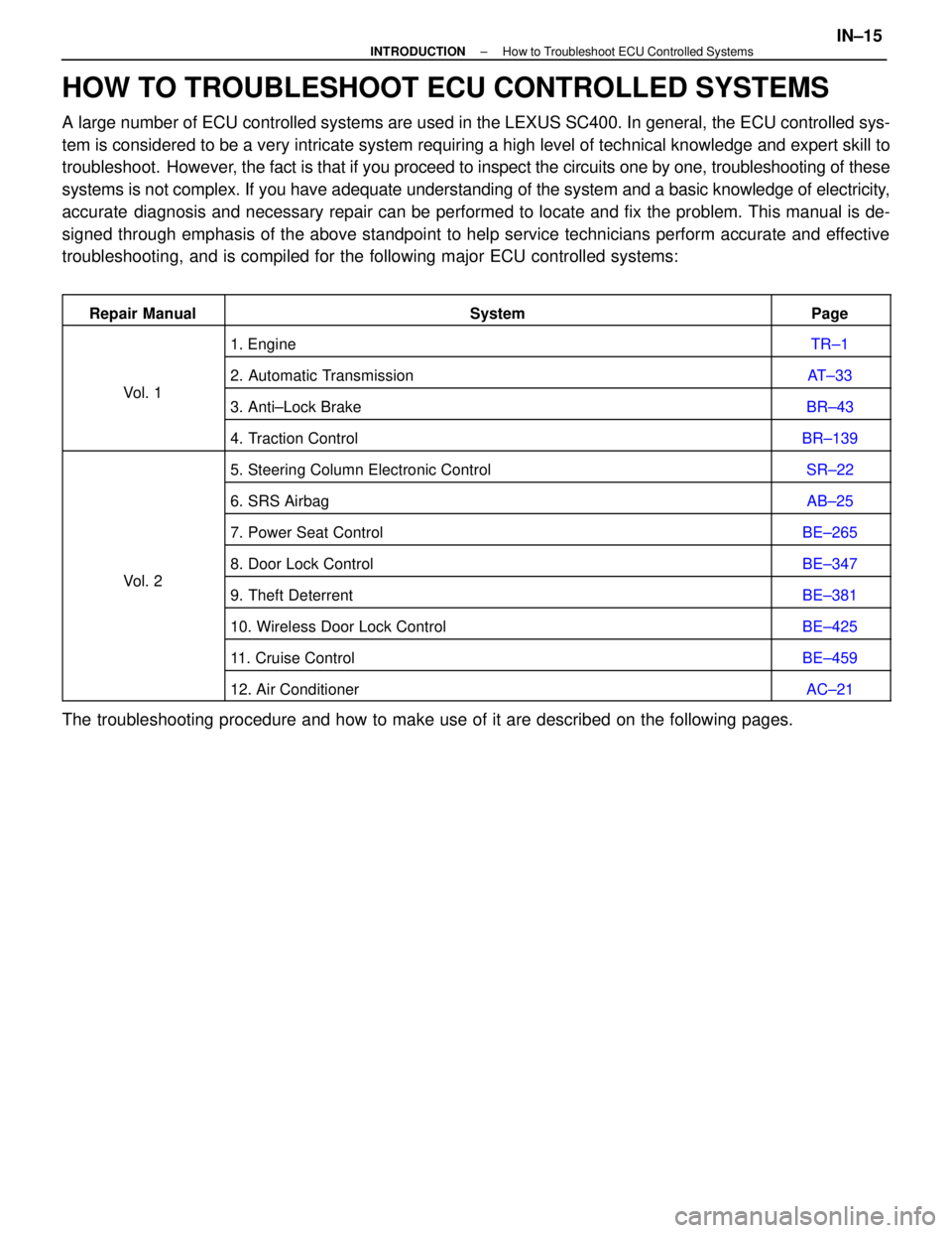
HOW TO TROUBLESHOOT ECU CONTROLLED SYSTEMS
A large number of ECU controlled systems are used in the LEXUS SC400. In \
general, the ECU controlled sys-
tem is considered to be a very intricate system requiring a high level o\
f technical knowledge and expert skill to
troubleshoot. However, the fact is that if you proceed to inspect the circuits one by one, trou\
bleshooting of these
systems is not complex. If you have adequate understanding of the system\
and a basic knowledge of electricity,
accurate diagnosis and necessary repair can be performed to locate and fix the p\
roblem. This manual is de-
signed through emphasis of the above standpoint to help service technici\
ans perform accurate and effective
troubleshooting, and is compiled for the following major ECU controlled \
systems:
Repair ManualSystemPage
1. EngineTR±1
Vl1
2. Automatic TransmissionAT±33
Vol. 13. Anti±Lock BrakeBR±43
4. Traction ControlBR±139
5. Steering Column Electronic ControlSR±22
6. SRS AirbagAB±25
7. Power Seat ControlBE±265
Vl2
8. Door Lock ControlBE±347
Vol. 29. Theft DeterrentBE±381
10. Wireless Door Lock ControlBE±425
11. Cruise ControlBE±459
12. Air ConditionerAC±21
The troubleshooting procedure and how to make use of it are described on\
the following pages.
±
INTRODUCTION How to Troubleshoot ECU Controlled SystemsIN±15
WhereEverybodyKnowsYourName
Page 21 of 4087
![LEXUS SC300 1991 Service Repair Manual
[2] SYMPTOM CONFIRMATION AND DIAGNOSTIC CODE CHECK
The diagnostic system in the LEXUS SC400 fulfills various functions. The fi\
rst function is the Diagnostic Code
Check in which a malfunction in the LEXUS SC300 1991 Service Repair Manual
[2] SYMPTOM CONFIRMATION AND DIAGNOSTIC CODE CHECK
The diagnostic system in the LEXUS SC400 fulfills various functions. The fi\
rst function is the Diagnostic Code
Check in which a malfunction in the](/manual-img/36/57052/w960_57052-20.png)
[2] SYMPTOM CONFIRMATION AND DIAGNOSTIC CODE CHECK
The diagnostic system in the LEXUS SC400 fulfills various functions. The fi\
rst function is the Diagnostic Code
Check in which a malfunction in the signal circuits to the ECU is stored\
in code in the ECU memory at the time
of occurrence, to be output by the technician during troubleshooting. Anot\
her function is the Input Signal Check
which checks if the signals from various switches are sent to the ECU correct\
ly.
The air conditioner system has an Actuator Check function whereby the ECU a\
utomatically operates the actua-
tors of the damper and blowermotor, etc. to check the operation. The cruise control system has a Cancel Si\
gnal
Check function which memorizes and displays what sort of signal it was that l\
ast cancelled the cruise control.
By using these check functions, the problem areas can be narrowed down qui\
ckly and troubleshooting can be
performed effectively. Diagnostic functions are incorporated in the following systems in the \
LEXUS SC400.
SystemDiagnostic CodeCheckInput Signal Check(Sensor Check)Other Diagnosis Function
Engine (with Test Mode)
Automatic Transmission (with Test Mode)
Anti±Lock Brake
Traction Control (Option)
SRS Airbag
Power Seat (only vehicles with memory function)
Wireless Door Lock Control
Cruise Control Cancel Signal
Check
Air Conditioner Actuator Check
In diagnostic code check, it is very important to determine whether the pr\
oblem indicated by the diagnostic code
is still occurring or occurred in the past but returned to normal at pre\
sent. In addition, it must be checked in the
problem sym ptom check whether the malfunction indicated by the diagnostic code is d\
irectly related to the prob-
lem symptom or not. For this reason, the diagnostic codes should be chec\
ked before and after the symptom
confirmation to determine the current conditions, as shown in the table below. If this is not done, it may, depend-
ing on the case, result in unnecessary troubleshooting for normally oper\
ating systems, thus making it more diffi-
cult to locate the problem, or in repairs not pertinent to the problem. Ther\
efore, always follow the procedure in
correct order and perform the diagnostic code check.
DIAGNOSTIC CODE CHECK PROCEDURE
IN±18±
INTRODUCTION How to Troubleshoot ECU Controlled Systems
WhereEverybodyKnowsYourName
Page 207 of 4087

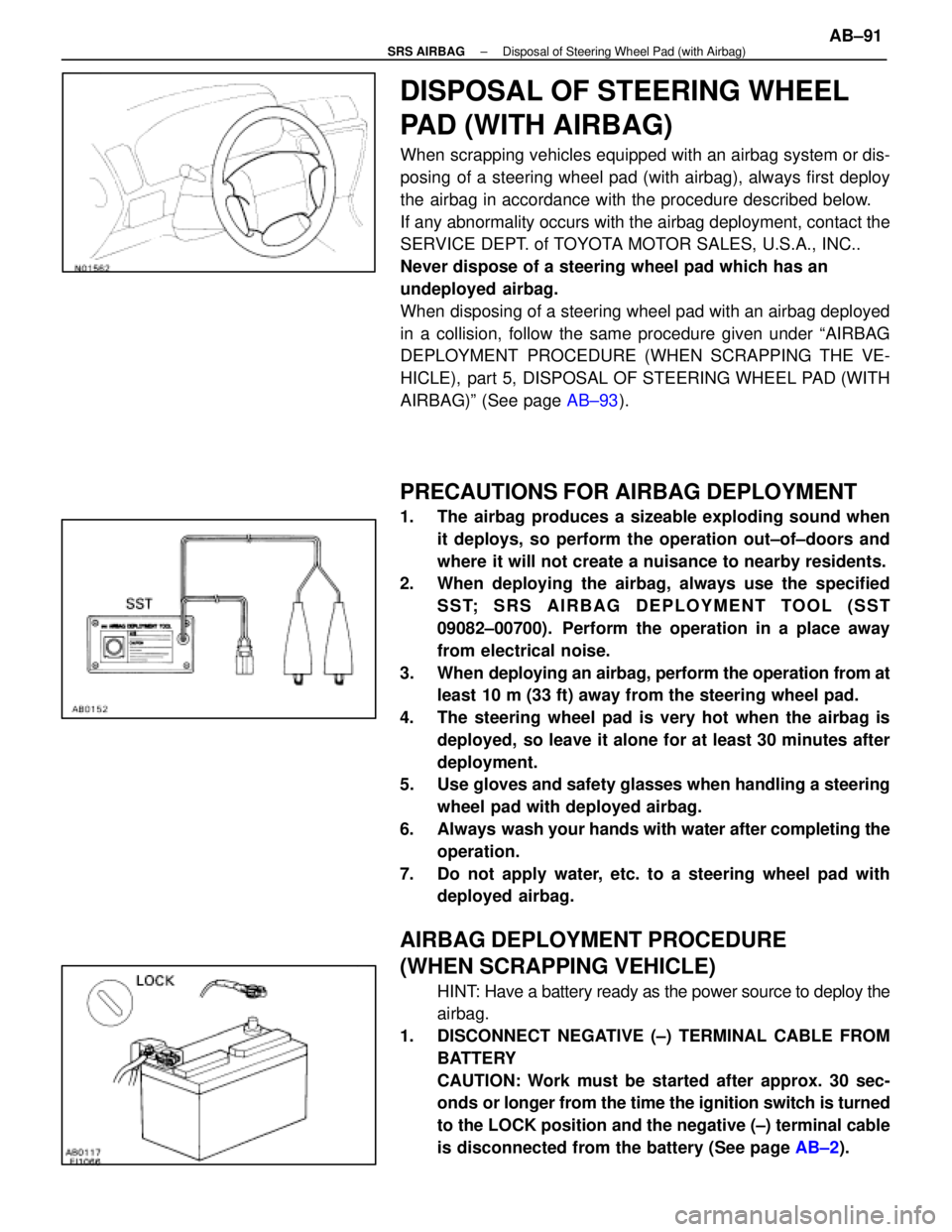
DISPOSAL OF STEERING WHEEL
PAD (WITH AIRBAG)
When scrapping vehicles equipped with an airbag system or dis-
posing of a steering wheel pad (with airbag), always first deploy
the airbag in accordance with the procedure described below.
If any abnormality occurs with the airbag deployment, contact the
SERVICE DEPT. of TOYOTA MOTOR SALES, U.S.A., INC..
Never dispose of a steering wheel pad which has an
undeployed airbag.
When disposing of a steering wheel pad with an airbag deployed
in a collision, follow the same procedure given under ªAIRBAG
DEPLOYMENT PROCEDURE (WHEN SCRAPPING THE VE-
HICLE), part 5, DISPOSAL OF STEERING WHEEL PAD (WITH
AIRBAG)º (See page AB±93).
PRECAUTIONS FOR AIRBAG DEPLOYMENT
1. The airbag produces a sizeable exploding sound when
it deploys, so perform the operation out±of±doors and
where it will not create a nuisance to nearby residents.
2. When deploying the airbag, always use the specified
SST; SRS AIRBAG DEPLOYMENT TOOL (SST
09082±00700). Perform the operation in a place away
from electrical noise.
3. When deploying an airbag, perform the operation from at least 10 m (33 ft) away from the steering wheel pad.
4. The steering wheel pad is very hot when the airbag is deployed, so leave it alone for at least 30 minutes after
deployment.
5. Use gloves and safety glasses when handling a steering
wheel pad with deployed airbag.
6. Always wash your hands with water after completing the operation.
7. Do not apply water, etc. to a steering wheel pad with deployed airbag.
AIRBAG DEPLOYMENT PROCEDURE
(WHEN SCRAPPING VEHICLE)
HINT: Have a battery ready as the power source to deploy the
airbag.
1. DISCONNECT NEGATIVE (±) TERMINAL CABLE FROM BATTERY
CAUTION: Work must be started after approx. 30 sec-
onds or lo nger from the time the ignition switch is turned
to the LOCK position and the negative (±) terminal cable
is disconnected from the battery (See page AB±2).
±
SRS AIRBAG Disposal of Steering Wheel Pad (with Airbag)AB±91
WhereEverybodyKnowsYourName
Page 398 of 4087
MIRROR
Outside Rear View Mirror
COMPONENTS
REMOVAL AND INSTALLATION OF
OUTSIDE REAR VIEW MIRROR
HINT: Install the mirror by following the removal sequence
in reverse.
1. DISCONNECT BATTERY CABLE FROM NEGATIVE TERMINAL
CAUTION: Work must be started after approx. 20 se-
conds or longer from the time the ignition switch is
turned to the ºLOCKº position and the negative (±) termi-
nal cable is disconnected from the battery.
2. REMOVE DOOR TRIM UPPER PANEL Removal: (See step 5 on page BO±34)
Installation: (See step 16 on page BO±40)
3. REMOVE MIRROR (a) Connect the connector, install the mirror with two bolts.
(b) Connect the connector, install the speaker with twobolts.
BO±42
±
BODY Mirror (Outside Rear View Mirror)
WhereEverybodyKnowsYourName
Page 430 of 4087
LUGGAGE COMPARTMENT
Fitting Adjustments
HINT: Adjust the door panel according to the following
method.
1. ADJUST LUGGAGE COMPARTMENT (a) For forward/rearward and vertical direction adjustments
loosen the bolts.
(b) For left and right adjustment of front end of the door, increase or decrease the number of washers between
the hinge and the door.
2. ADJUST LOCK STRIKER (a) Remove the trim rear cover.
(b) Using a hammer and brass bar, tap the door lock toadjust it.
BO±74
±
BODY Luggage Com partment (Fitting Adjustments)
WhereEverybodyKnowsYourName
Page 433 of 4087
(b) Remove the clip, loosen the bolt disconnect the doorsupport.
(c) Remove the door support.
3. IF NECESSARY, REPLACE DOOR SUPPORT (See step 3 on page BO±23)
INSTALLATION OF LUGGAGE
COMPARTMENT DOOR
(See page BO±76)
INSTALL LUGGAGE COMPARTMENT DOOR PARTS BY FOL-
LOWING REMOVAL SEQUENCE IN REVERSE
DISASSEMBLY OF LUGGAGE
COMPARTMENT DOOR
(See page BO±76)
1. REMOVE LOCK STRIKER Remove two bolts and the striker.
2. REMOVE CUSHION
3. REMOVE NAME PLATE AND EMBLEM (See page BO±94)
ASSEMBLY OF LUGGAGE
COMPARTMENT DOOR
(See page BO±76)
ASSEMBLE THE LUGGAGE COMPARTMENT DOOR PARTS
BY FOLLOWING DISASSEMBLY SEQUENCE IN REVERSE
±
BODY Luggage Compartment (Luggage Compartment Door)BO±77
WhereEverybodyKnowsYourName
Page 525 of 4087
2. ADJUST FRONT DOOR IN LEFT/RIGHT AND VERTICALDIRECTIONS
Loosen the door side hinge bolts to adjust.
3. ADJUST FRONT DOOR LOCK STRIKER (a) Check that the door fit and door lock link ages are
adjusted correctly.
(b) Using a screwdriver, remove the striker cover.
HINT: Tape the screwdriver tip before use.
(c) Adjust the striker position by slightly loosening the striker mounting screws, and hitting the striker with a
hammer. Tighten the striker mounting screws again.
(d) Install the striker cover.
BO±30
±
BODY Front Door (Fitting Adjustments)
WhereEverybodyKnowsYourName
Page 531 of 4087
14. REMOVE FRONT DOOR INNER WEATHERSTRIPPry loose the clips from the edge of the panel and remove the
belt moulding.
15. REMOVE FRONT GLASS GUIDE Remove three screws and the guide.
16. REMOVE REAR GLASS GUIDE AND DOOR GLASS (a) Remove four screws from the guide.
(b) Remove joining the window regulator and glass.
(c) Pull the door glass with the guide out of the panel carefully.
HINT: Do not remove the guide from the glass.
17. REMOVE WINDOW REGULATOR Remove six nuts and the regulator.
18. REMOVE DOOR LOCK (a) Disconnect the two links from the outside handle andkey cylinder.
(b) Disconnect the connector.
(c) Using a trox rench, remove three screws and the door lock.
BO±36
±
BODY Front Door
WhereEverybodyKnowsYourName