Page 506 of 4087
REMOVAL OF FRONT BUMPER
(See page BO±11)
1. REMOVE FENDER SPLASH SHIELD Remove fourteen screws, a bolt and the shield.
2. REMOVE NO. 2 ENGINE UNDER COVER Remove seven screws, five bolts and the cover.
3. REMOVE HEADLIGHT (Low Beam)
(a) Remove two nuts, a bolt and the headlight.
(b) Disconnect the connectors.
4. REMOVE UPPER BUMPER RETAINER (a) Remove the hood seal.
(b) Remove five screws and the retainer.
5. REMOVE BUMPER COVER ASSY (a) Remove six clips.
BO±12
±
BODY Bumper (Front Bumper)
WhereEverybodyKnowsYourName
Page 519 of 4087
REMOVAL OF HOOD LOCK CONTROL
(See page BO±24)
1. REMOVE FOLLOWING PARTS: (a) Front bumper
(b) LH front fender wheel opening moulding
(c) LH fender liner
(d) Fender splash shield
(e) Hood release lever
2. REMOVE HOOD LOCK (a) Remove two bolts, the nut and the hood lock.
(b) Disconnect the link from the lock.
3. REMOVE HOOD LOCK CONTROL CABLE (a) Disconnect the cable from clamps.
(b) Using the screwdriver, pry out the cable stopper fromgrommet.
HINT: Do not damage the grommet with the screwdriver.
±
BODY Hood (Hood Lock Control)BO±25
WhereEverybodyKnowsYourName
Page 520 of 4087
(c) Pull the cable from front wheel housing to remove it.
INSTALLATION OF HOOD LOCK
CONTROL
(See page BO±24)
1. BEFORE INSTALLING PARTS, COAT LOCK WITH MP GREASE
Apply MP grease to the sliding surface of the lock.
2. INSTALL HOOD LOCK CONTROL CABLE (a) Push the rear side cable through the grommet.
(b) Using the screwdriver, push the cable stopper into thegrommet.
HINT: Do not damage the grommet with the screwdriver.
(c) Clamp the cable to the junction block.
(d) Pass the front side cable through the upper radiator
support.
3. INSTALL HOOD RELEASE LEVER
4. INSTALL HOOD LOCK TEMPORARILY
5. CHECK HOOD LOCK CONTROL FOR PROPER OPERATION
After checking for proper operation, tighten the nut and two
bolts to install the lock.
6. INSTALL FOLLOWING PARTS: (a) Hood release lever
(b) Fender splash shield
(c) LH fender liner
(d) LH front fender wheel opening moulding
(e) Front bumper
BO±26
±
BODY Hood (Hood Lock Control)
WhereEverybodyKnowsYourName
Page 521 of 4087
TRANSPORT HOOK
COMPONENTS
Front Transport Hook
REMOVAL AND INSTALLATION
1. REMOVE FENDER SPLASH SHIELDRemove fourteen screws, a bolt and the shield.
±
BODY Transport Hook (Front Transport Hook)BO±27
WhereEverybodyKnowsYourName
Page 522 of 4087
2. REMOVE NO. 4 ENGINE UNDER COVER
3. REMOVE FRONT TRANSPORT HOOKRemove three bolts and the hook.
4. INSTALL FRONT TRANSPORT HOOK Install the hook with three bolts.
Torque: 64 N Vm (650 kgf Vcm, 47 ft Vlbf)
5. INSTALL NO. 4 ENGINE UNDER
6. INSTALL FENDER SPLASH SHIELD
Rear Transport Hook
REMOVAL AND INSTALLATION
(See page BO±27)
1. REMOVE SUPPORT Remove two bolts and the support.
2. REMOVE REAR TRANSPORT HOOK Remove two bolts and the hook.
3. INSTALL REAR TRANSPORT HOOK Install the hook with two bolts.
Torque: 64 N Vm (650 kgf Vcm, 47 ft Vlbf)
4. INSTALL SUPPORT
Install the support with two bolts.
BO±28
±
BODY Transport Hook (Front Transport Hook, Rear Transport Hook)
WhereEverybodyKnowsYourName
Page 523 of 4087
2. REMOVE NO. 4 ENGINE UNDER COVER
3. REMOVE FRONT TRANSPORT HOOKRemove three bolts and the hook.
4. INSTALL FRONT TRANSPORT HOOK Install the hook with three bolts.
Torque: 64 N Vm (650 kgf Vcm, 47 ft Vlbf)
5. INSTALL NO. 4 ENGINE UNDER
6. INSTALL FENDER SPLASH SHIELD
Rear Transport Hook
REMOVAL AND INSTALLATION
(See page BO±27)
1. REMOVE SUPPORT Remove two bolts and the support.
2. REMOVE REAR TRANSPORT HOOK Remove two bolts and the hook.
3. INSTALL REAR TRANSPORT HOOK Install the hook with two bolts.
Torque: 64 N Vm (650 kgf Vcm, 47 ft Vlbf)
4. INSTALL SUPPORT
Install the support with two bolts.
BO±28
±
BODY Transport Hook (Front Transport Hook, Rear Transport Hook)
WhereEverybodyKnowsYourName
Page 1157 of 4087
Front Door Trim Upper Panel (ABS/PVC)
Battery Insulator (PE) Roof Side Inner Garnish (ABS/PVC)
Front Pillar Garnish (ABS/PVC)
Speed Control Actuator Cover (PP)
Radiator Reserver Tank (PP)
Radiator Cover Plate (PP) Cool Air Intake
Duct (PP)
Spare Wheel Cover (PP)
Washer Jar (PP)
Junction Block Cover (PP)
Front Fender Liner (PE)
Front Fender Splash Shield (PE)
Engine Under Cover (PE) Engine Under Cover (PE)
Engine Under Cover (PP/PE)
HINT:
wResin material differs with model.
/ Made up of 2 or more kinds of materials.
PLASTIC BODY PARTSPP-5
WhereEverybodyKnowsYourName
Page 1880 of 4087

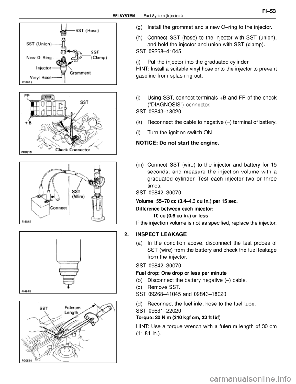
(g) Install the grommet and a new O±ring to the injector.
(h) Connect SST (hose) to the injector with SST (union),and hold the injector and union with SST (clamp).
SST 09268±41045
(i) Put the injector into the graduated cylinder.
HINT: Install a suitable vinyl hose onto the injector to prevent
gasoline from splashing out.
(j) Using SST, connect terminals +B and FP of the check (ºDIAGNOSISº) connector.
SST 09843±18020
(k) Reconnect the cable to negative (±) terminal of battery.
(l) Turn the ignition switch ON.
NOTICE: Do not start the engine.
(m) Connect SST (wire) to the injector and battery for 15 seconds, and measure the injection volume with a
graduated cylinder. Test each injector two or three
times.
SST 09842±30070
Volume: 55±70 cc (3.4±4.3 cu in.) per 15 sec.
Difference between each injector:
10 cc (0.6 cu in.) or less
If the injection volume is not as specified, replace the injector.
2. INSPECT LEAKAGE (a) In the condition above, disconnect the test probes ofSST (wire) from the battery and check the fuel leakage
from the injector.
SST 09842±30070
Fuel drop: One drop or less per minute
(b) Disconnect the battery negative (±) cable.
(c) Remove SST.
SST 09268±41045 and 09843±18020
(d) Reconnect the fuel inlet hose to the fuel tube.
SST 09631±22020
Torque: 30 N Vm (310 kgf Vcm, 22 ft Vlbf)
HINT: Use a torque wrench with a fulerum length of 30 cm
(11.81 in.). FI±53
EFI SYSTEM
± Fuel System (Injectors)
WhereEverybodyKnowsYourName