Page 223 of 4087
INSPECTION ITEMS AND REPLACEMENT REQUIREMENTS
If a Vehicle is brought in for an airbag system inspection, or if a vehicle wh\
ich has been involved in a collision
is inspected, perform the inspection in accordance with the following proc\
edure. If any problems are discovered,
replace the affected part with a new one.
Steering Wheel Pad (with Airbag), Steering Wheel and Spiral
Cable
INSPECTION ITEMS
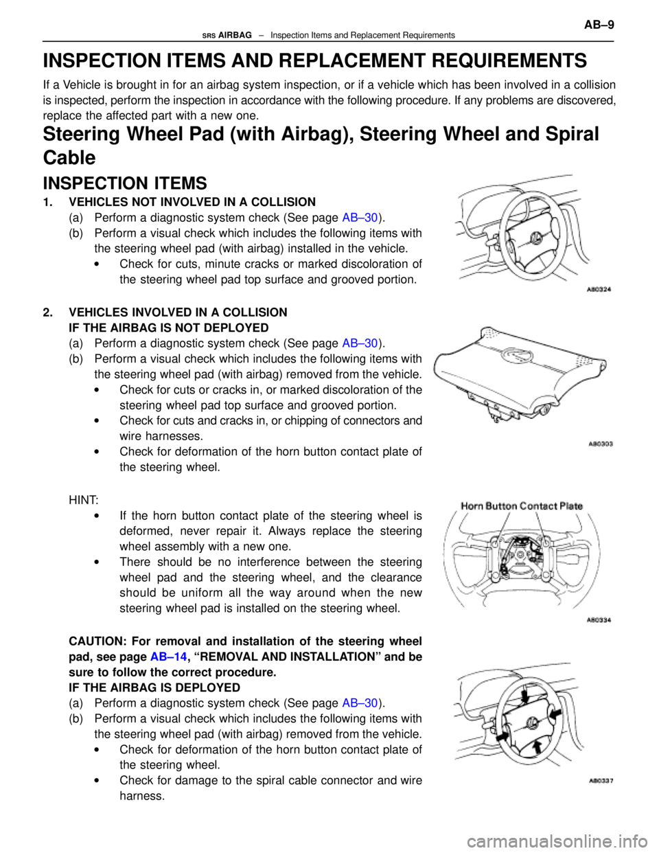
1. VEHICLES NOT INVOLVED IN A COLLISION(a) Perform a diagnostic system check (See page AB±30).
(b) Perform a visual check which includes the following items with the steering wheel pad (with airbag) installed in the vehicle.
w Check for cuts, minute cracks or marked discoloration of
the steering wheel pad top surface and grooved portion.
2. VEHICLES INVOLVED IN A COLLISION IF THE AIRBAG IS NOT DEPLOYED
(a) Perform a diagnostic system check (See page AB±30).
(b) Perform a visual check which includes the following items with the steering wheel pad (with airbag) removed from the vehicle.
w Check for cuts or cracks in, or marked discoloration of the
steering wheel pad top surface and grooved portion.
w Check for cuts and cracks in, or chipping of connectors and
wire harnesses.
w Check for deformation of the horn button contact plate of
the steering wheel.
HINT: w If the horn button contact plate of the steering wheel is
deformed, never repair it. Always replace the steering
wheel assembly with a new one.
w There should be no interference between the steering
wheel pad and the steering wheel, and the clearance
should be uniform all the way around when the new
steering wheel pad is installed on the steering wheel.
CAUTION: For removal and installation of the steering wheel
pad, see page AB±14, ªREMOVAL AND INSTALLATIONº and be
sure to follow the correct procedure.
IF THE AIRBAG IS DEPLOYED
(a) Perform a diagnostic system check (See page AB±30).
(b) Perform a visual check which includes the following items with the steering wheel pad (with airbag) removed from the vehicle.
w Check for deformation of the horn button contact plate of
the steering wheel.
w Check for damage to the spiral cable connector and wire
harness.
AB±9SRS AIRBAG ± Inspection Items and Replacement Requirements
WhereEverybodyKnowsYourName
Page 224 of 4087
HINT:
w If the horn button contact plate of the steering wheel is deformed, never \
repair it. Always replace the
steering wheel assembly with a new one.
w There should be no interference between the steering wheel pad and the steeri\
ng wheel, and the
clearance should be uniform all the way around when the new steering wheel pad is\
installed on the
steering wheel.
REPLACEMENT REQUIREMENTS
In the following cases, replace the steering wheel pad, steering wheel or \
spiral cable.
CAUTION: For replacement of the steering wheel pad, see page AB±16, ªREMOVAL AND INSTALLA-
TIONº and be sure to follow the correct procedure.
w If the airbag has been deployed.
w If the steering wheel pad or spiral cable has been found to be faulty in\
troubleshooting.
w If the steering wheel pad, steering wheel or spiral cable has been found t\
o be faulty during the check
in item 1±(b) or 2±(b).
w If the steering wheel pad has been dropped.
Front Airbag Sensor
INSPECTION ITEMS
1. VEHICLES NOT INVOLVED IN A COLLISION
w Perform a diagnostic system check (See page AB±30).
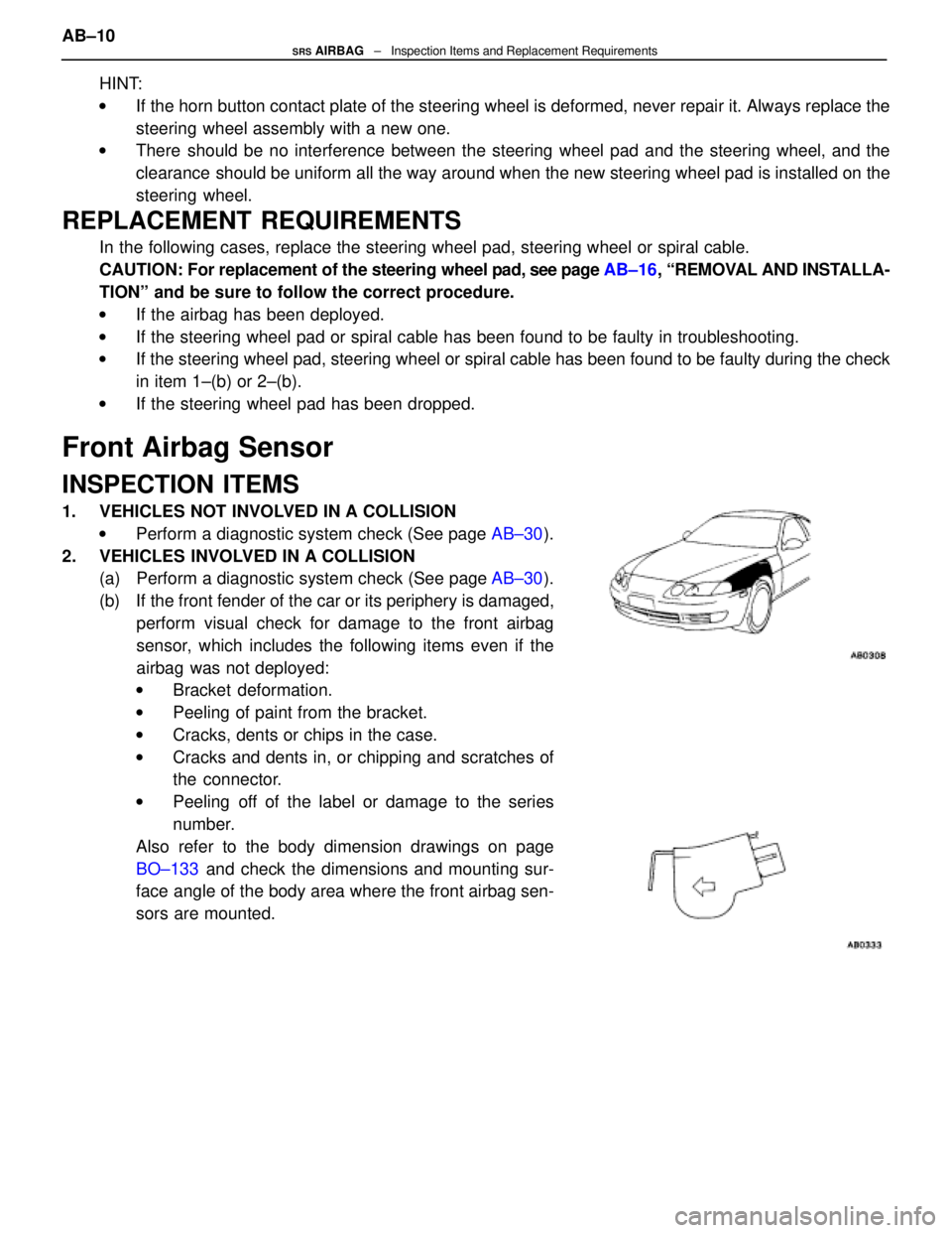
2. VEHICLES INVOLVED IN A COLLISION (a) Perform a diagnostic system check (See page AB±30).
(b) If the front fender of the car or its periphery is damaged, perform visual check for damage to the front airbag
sensor, which includes the following items even if the
airbag was not deployed:
w Bracket deformation.
w Peeling of paint from the bracket.
w Cracks, dents or chips in the case.
w Cracks and dents in, or chipping and scratches of
the connector.
w Peeling off of the label or damage to the series
number.
Also refer to the body dimension drawings on page
BO±133 and check the dimensions and mounting sur-
face angle of the body area where the front airbag sen-
sors are mounted.
AB±10SRS AIRBAG ± Inspection Items and Replacement Requirements
WhereEverybodyKnowsYourName
Page 645 of 4087
31NoiseNOISE PRODUCED WHEN ENGINE STARTS
Whistling noise which becomes high±pitched when
accelerator strongly depressed, disappears shortly
after engine stops.Whining noise occurs when A/C is operating.
Scratching noise occurs during sudden accel-
eration, driving on rough roads or when ignition
switch is turned on.
Clicking sound heard when horn button is
pressed, then released. Whirring/grating sound
when pushed continuously.
Murmuring sound, stops when engine stops. Tick±tock noise, occurs in coordination with
blinking of flasher.
Noise occurs during window washer operation.Scratching noise occurs while engine is running,
continues a while even after engine stops.Scraping noise in time with wiper beat.
Other type of noise. Alternator noise.
A/C noise.
Fuel gauge noise.
Horn noise.
Ignition noise. Turn signal flasher noise.
Washer noise. Water temp. gauge noise.
Wiper noise.
±
BODY ELECTRICAL SYSTEM AUDIO SYSTEMBE±259
WhereEverybodyKnowsYourName
Page 648 of 4087
HORN SYSTEM
PARTS LOCATION
WIRING AND CONNECTOR DIAGRAMS
BE±262±
BODY ELECTRICAL SYSTEM HORN SYSTEM
WhereEverybodyKnowsYourName
Page 649 of 4087
Parts Inspection
(Horn Switch)
INSPECTION OF HORN SWITCH
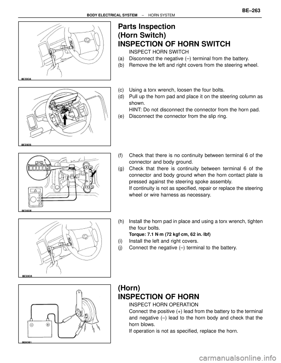
INSPECT HORN SWITCH
(a) Disconnect the negative (±) terminal from the battery.
(b) Remove the left and right covers from the steering wheel.
(c) Using a torx wrench, loosen the four bolts.
(d) Pull up the horn pad and place it on the steering column as shown.
HINT: Do not disconnect the connector from the horn pad.
(e) Disconnect the connector from the slip ring.
(f) Check that there is no continuity between terminal 6 of the
connector and body ground.
(g) Check that there is continuity between terminal 6 of the connector and body ground when the horn contact plate is
pressed against the steering spoke assembly.
If continuity is not as specified, repair or replace the steering
wheel or wire harness as necessary.
(h) Install the horn pad in place and using a torx wrench, tighten the four bolts.
Torque: 7.1 N Vm (72 kgf Vcm, 62 in. Vlbf)
(i) Install the left and right covers.
(j) Connect the negative (±) terminal to the battery.
(Horn)
INSPECTION OF HORN
INSPECT HORN OPERATION
Connect the positive (+) lead from the battery to the terminal
and negative (±) lead to the horn body and check that the
horn blows.
If operation is not as specified, replace the horn.
±
BODY ELECTRICAL SYSTEM HORN SYSTEMBE±263
WhereEverybodyKnowsYourName
Page 650 of 4087
HORN RELAY
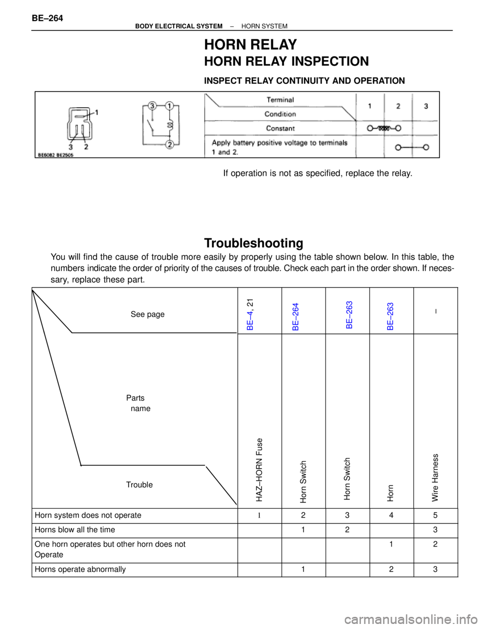
HORN RELAY INSPECTION
INSPECT RELAY CONTINUITY AND OPERATION
If operation is not as specified, replace the relay.
Troubleshooting
You will find the cause of trouble more easily by properly using the tabl\
e shown below. In this table, the
numbers indicate the order of priority of the causes of trouble. Check each part in \
the order shown. If neces-
sary, replace these part.
See page
BE±4 , 21BE±264BE±263BE±263
±
Trouble
Parts
name
HAZ±HORN FuseHorn SwitchHorn SwitchHornWire Harness
������������������\
������������������\
Horn system does not operate����� �����1���� ����2����� �����3���� ����4����� �����5������������������\
�
�����������������
������������������\
Horns blow all the time
����� �
����
�����
���� �
���
����1
����� �
����
�����2
���� �
���
����
����� �
����
�����3
������������������\
�
�����������������
������������������\
One horn operates but other horn does not
Operate����� �
����
�����
���� �
���
����
����� �
����
�����
���� �
���
����
1����� �
����
�����
2
������������������\
������������������\
Horns operate abnormally����� ��������� ����1����� ��������� ����2����� �����3
BE±264±
BODY ELECTRICAL SYSTEM HORN SYSTEM
WhereEverybodyKnowsYourName
Page 815 of 4087
No.Part NameRelated Systems or Parts
22MAIN � Upstream of ALT±S and EFI Fuse
23AM2 � Charging System � Engine23AM2 � AIR±BAG System
24ABS NO. 2 � ABS and TRAC
25INJ � Charging System � Engine25INJ � AIR±BAG System
26DEF � Defogger System
� Power Seat System � Sliding Roof System
� A/C System � Liquid Crystal Inner Mirror System
27DOME � Combination Meter System � Interior Light System27DOME � ABS and TRAC � Wireless Door Lock Control System
� Cruise Control System � Auto±Tilt away Steering
� Theft Deterrent System
28EFI � Engine
29HAZ HORN � Turn Signal and Hazard Warning Light System29HAZ±HORN � Horn System
30RADIO NO. 1 � Audio System
31TEL � TEL System
32ALT±S � Charging System
33TRAC � ABS and TRAC
34HEAD (RH±LWR) � Headlight System
35HEAD (LH±LWR) � Headlight System
36HEAD (RH±UPR) � Headlight System
37HEAD (LH±UPR) � Headlight System
38HTR � Blow Motor
±
BODY ELECTRICAL SYSTEM Power SourceBE±19
WhereEverybodyKnowsYourName
Page 818 of 4087
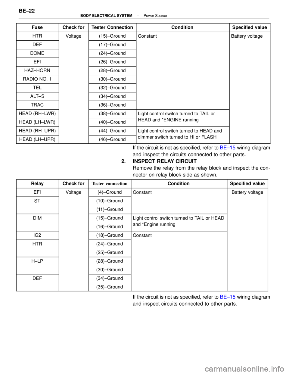
FuseCheck forTester ConnectionConditionSpecified value
HTRVoltage(15)±GroundConstantBattery voltage
DEF(17)±Ground
DOME(24)±Ground
EFI(26)±Ground
HAZ±HORN(28)±Ground
RADIO NO. 1(30)±Ground
TEL(32)±Ground
ALT±S(34)±Ground
TRAC(36)±Ground
HEAD (RH±LWR)(38)±GroundLight control switch turned to TAIL or
HEAD (LH±LWR)(40)±GroundHEAD and *ENGINE running
HEAD (RH±UPR)(44)±GroundLight control switch turned to HEAD and
HEAD (LH±UPR)(46)±Grounddimmer switch turned to HI or FLASH
If the circuit is not as specified, refer to BE±15 wiring diagram
and inspect the circuits connected to other parts.
2. INSPECT RELAY CIRCUIT Remove the relay from the relay block and inspect the con-
nector on relay block side as shown.
RelayCheck forTester connectionConditionSpecified value
EFIVoltage(4)±GroundConstantBattery voltage
ST(10)±Ground
(11)±Ground
DIM(15)±GroundLight control switch turned to TAIL or HEAD
(16)±Groundand *Engine running
IG2(18)±GroundConstant
HTR(24)±Ground
(25)±Ground
H±LP(28)±Ground
(30)±Ground
DEF(34)±Ground
(35)±Ground
If the circuit is not as specified, refer to BE±15 wiring diagram
and inspect circuits connected to other parts.
BE±22
±
BODY ELECTRICAL SYSTEM Power Source
WhereEverybodyKnowsYourName