Page 212 of 4087
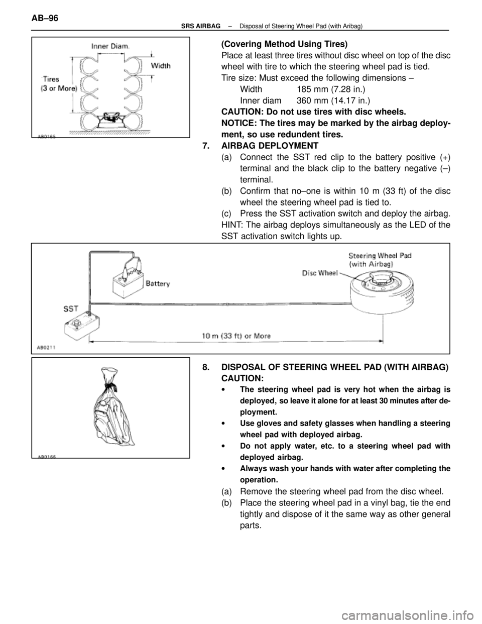
(Covering Method Using Tires)
Place at least three tires without disc wheel on top of the disc
wheel with tire to which the steering wheel pad is tied.
Tire size: Must exceed the following dimensions ±Width 185 mm (7.28 in.)
Inner diam 360 mm (14.17 in.)
CAUTION: Do not use tires with disc wheels.
NOTICE: The tires may be marked by the airbag deploy-
ment, so use redundent tires.
7. AIRBAG DEPLOYMENT (a) Connect the SST red clip to the battery positive (+)terminal and the black clip to the battery negative (±)
terminal.
(b) Confirm that no±one is within 10 m (33 ft) of the disc wheel the steering wheel pad is tied to.
(c) Press the SST activation switch and deploy the airbag.
HINT: The airbag deploys simultaneously as the LED of the
SST activation switch lights up.
8. DISPOSAL OF STEERING WHEEL PAD (WITH AIRBAG) CAUTION:
w The steering wheel pad is very hot when the airbag is
deployed, so leave it alone for at least 30 minutes after de-
ployment.
w Use gloves and safety glasses when handling a steering
wheel pad with deployed airbag.
w Do not apply water, etc. to a steering wheel pad with
deployed airbag.
w Always wash your hands with water after completing the
operation.
(a) Remove the steering wheel pad from the disc wheel.
(b) Place the steering wheel pad in a vinyl bag, tie the end
tightly and dispose of it the same way as other general
parts.
AB±96
±
SRS AIRBAG Disposal of Steering Wheel Pad (with Aribag)
WhereEverybodyKnowsYourName
Page 224 of 4087
HINT:
w If the horn button contact plate of the steering wheel is deformed, never \
repair it. Always replace the
steering wheel assembly with a new one.
w There should be no interference between the steering wheel pad and the steeri\
ng wheel, and the
clearance should be uniform all the way around when the new steering wheel pad is\
installed on the
steering wheel.
REPLACEMENT REQUIREMENTS
In the following cases, replace the steering wheel pad, steering wheel or \
spiral cable.
CAUTION: For replacement of the steering wheel pad, see page AB±16, ªREMOVAL AND INSTALLA-
TIONº and be sure to follow the correct procedure.
w If the airbag has been deployed.
w If the steering wheel pad or spiral cable has been found to be faulty in\
troubleshooting.
w If the steering wheel pad, steering wheel or spiral cable has been found t\
o be faulty during the check
in item 1±(b) or 2±(b).
w If the steering wheel pad has been dropped.
Front Airbag Sensor
INSPECTION ITEMS
1. VEHICLES NOT INVOLVED IN A COLLISION
w Perform a diagnostic system check (See page AB±30).
2. VEHICLES INVOLVED IN A COLLISION (a) Perform a diagnostic system check (See page AB±30).
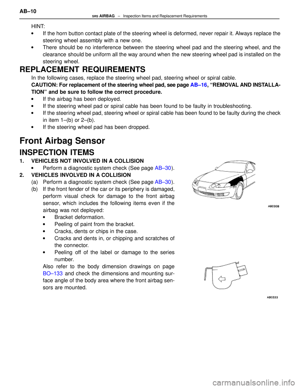
(b) If the front fender of the car or its periphery is damaged, perform visual check for damage to the front airbag
sensor, which includes the following items even if the
airbag was not deployed:
w Bracket deformation.
w Peeling of paint from the bracket.
w Cracks, dents or chips in the case.
w Cracks and dents in, or chipping and scratches of
the connector.
w Peeling off of the label or damage to the series
number.
Also refer to the body dimension drawings on page
BO±133 and check the dimensions and mounting sur-
face angle of the body area where the front airbag sen-
sors are mounted.
AB±10SRS AIRBAG ± Inspection Items and Replacement Requirements
WhereEverybodyKnowsYourName
Page 231 of 4087
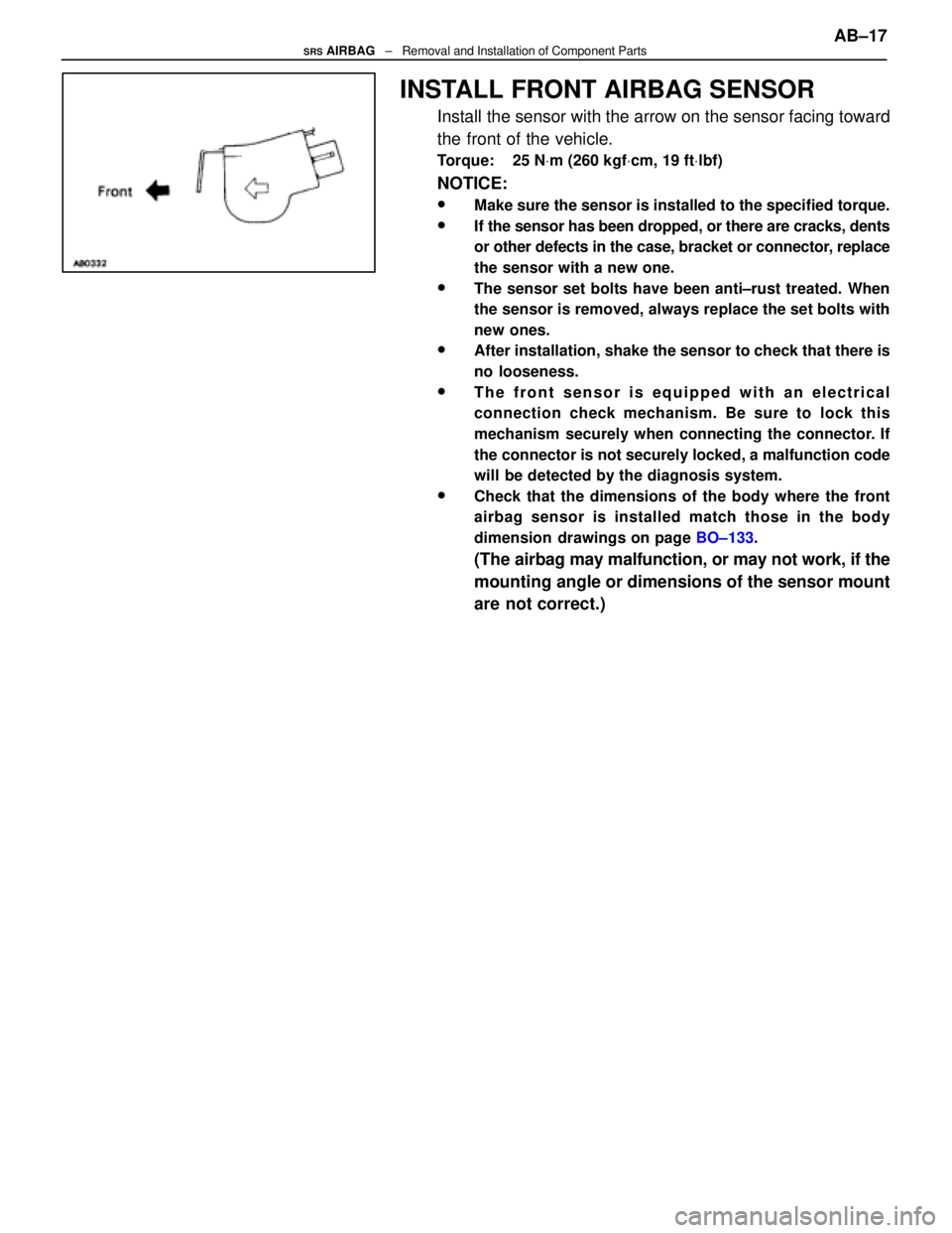
INSTALL FRONT AIRBAG SENSOR
Install the sensor with the arrow on the sensor facing toward
the front of the vehicle.
Torque: 25 NVm (260 kgf Vcm, 19 ft Vlbf)
NOTICE:
wMake sure the sensor is installed to the specified torque.
wIf the sensor has been dropped, or there are cracks, dents
or other defects in the case, bracket or connector, replace
the sensor with a new one.
wThe sensor set bolts have been anti±rust treated. When
the sensor is removed, always replace the set bolts with
new ones.
wAfter installation, shake the sensor to check that there is
no looseness.
wThe front sensor is equipped with an electrical
connection check mechanism. Be sure to lock this
mechanism securely when connecting the connector. If
the connector is not securely locked, a malfunction code
will be detected by the diagnosis system.
wCheck that the dimensions of the body where the front
airbag sensor is installed match those in the body
dimension drawings on page BO±133.
(The airbag may malfunction, or may not work, if the
mounting angle or dimensions of the sensor mount
are not correct.) AB±17
SRS AIRBAG
± Removal and Installation of Component Parts
WhereEverybodyKnowsYourName
Page 482 of 4087
BODY DIMENSIONS
Description
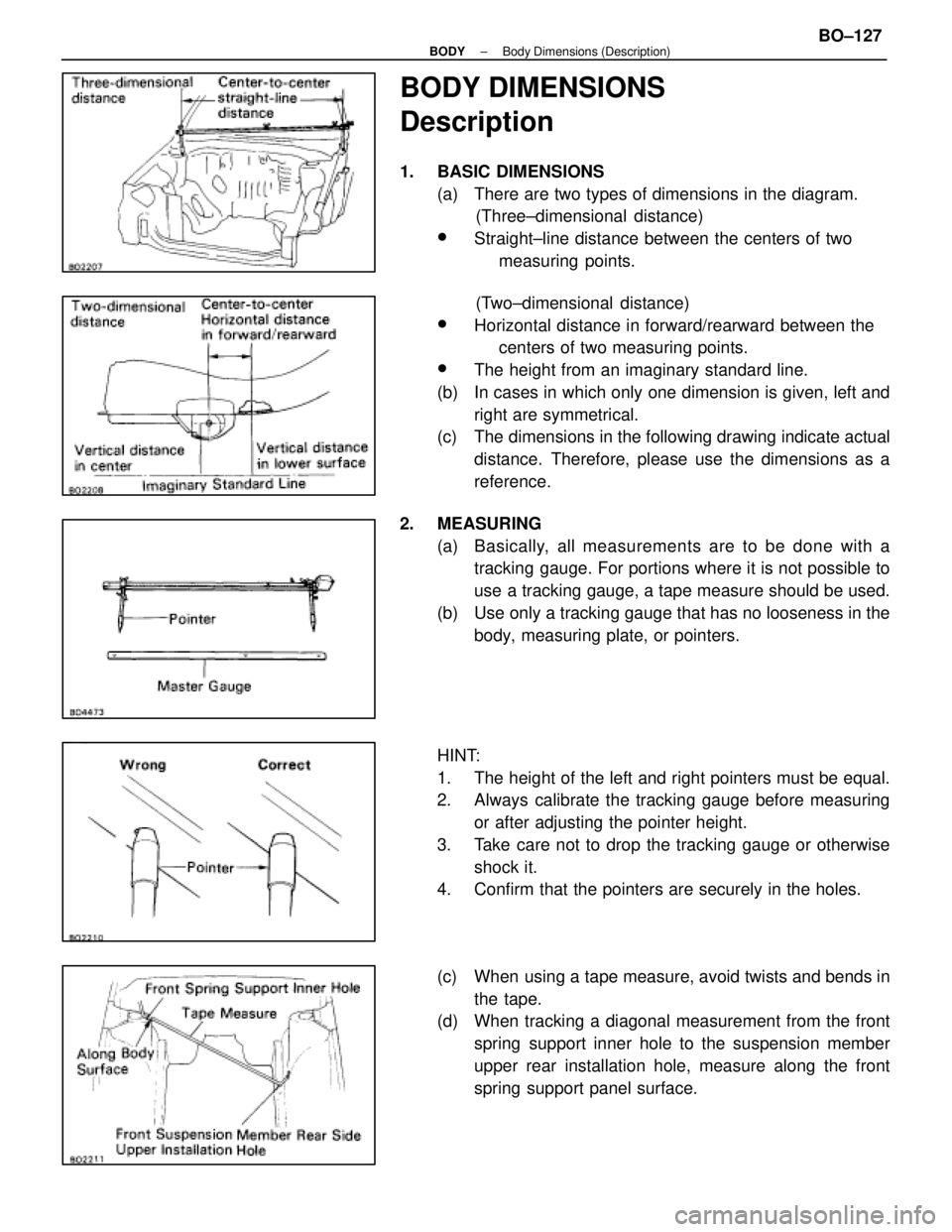
1. BASIC DIMENSIONS(a) There are two types of dimensions in the diagram. (Three±dimensional distance)
wStraight±line distance between the centers of two
measuring points.
(Two±dimensional distance)
wHorizontal distance in forward/rearward between the centers of two measuring points.
wThe height from an imaginary standard line.
(b) In cases in which only one dimension is given, left and right are symmetrical.
(c) The dimensions in the following drawing indicate actual
distance. Therefore, please use the dimensions as a
reference.
2. MEASURING (a) Basically, all measurements are to be done with atracking gauge. For portions where it is not possible to
use a tracking gauge, a tape measure should be used.
(b) Use only a tracking gauge that has no looseness in the body, measuring plate, or pointers.
HINT:
1. The height of the left and right pointers must be equal.
2. Always calibrate the tracking gauge before measuring or after adjusting the pointer height.
3. Take care not to drop the tracking gauge or otherwise shock it.
4. Confirm that the pointers are securely in the holes.
(c) When using a tape measure, avoid twists and bends in
the tape.
(d) When tracking a diagonal measurement from the front
spring support inner hole to the suspension member
upper rear installation hole, measure along the front
spring support panel surface.
±
BODY Body Dimensions (Description)BO±127
WhereEverybodyKnowsYourName
Page 483 of 4087
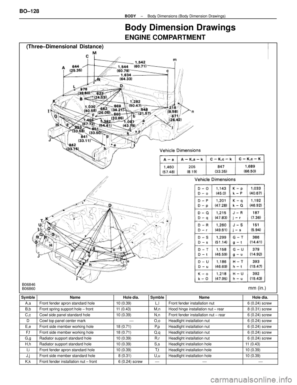
Body Dimension Drawings
ENGINE COMPARTMENT
(Three±Dimensional Distance)
mm (in.)B06846
B06860
Symble
NameHole dia.SymbleNameHole dia.
A,aFront fender apron standard hole10 (0.39)L,lFront fender installation nut6 (0.24) screw
B,bFront spring support hole ± front11 (0.43)M,nHood hinge installation nut ± rear8 (0.31) screw
C,cCowl side panel standard hole10 (0.39)N,nFront fender installation nut ± rear6 (0.24) screw
DCowl top panel center mark'O,oHeadlight installation nut6 (0.24) screw
E,eFront side member working hole18 (0.71)P, pHeadlight installation nut6 (0.24) screw
F, fFront side member working hole18 (0.71)Q,qHeadlight installation nut6 (0.24) screw
G,gRadiator support standard hole10 (0.39)R,rHeadlight installation nut6 (0.24) screw
H,hRadiator support standard hole10 (0.39)S,sHeadlight installation hole11 (0.43)
I,iFront fender apron standard hole10 (0.39)T, tHeadlight installation hole10 (0.39)
J,jFront side member standard hole8 (0.31)U,uHeadlight installation hole10 (0.39)
K,kFront fender installation nut ± front6 (0.24) screw'''
BO±128±
BODY Body Dimensions (Body Dimension Drawings)
WhereEverybodyKnowsYourName
Page 484 of 4087
UNDER BODY
(Three±Dimensional Distance)
±
BODY Body Dimensions (Body Dimension Drawings)BO±129
WhereEverybodyKnowsYourName
Page 485 of 4087
UNDER BODY (Cont'd)
(Three±Dimensional Distance)
BO±130
±
BODY Body Dimensions (Body Dimension Drawings)
WhereEverybodyKnowsYourName
Page 486 of 4087
UNDER BODY (Cont'd)
(Two±Dimensional Distance)
B06847
±
BODY Body Dimensions (Body Dimension Drawings)BO±131
WhereEverybodyKnowsYourName