Page 1171 of 4087
mm in.50
70 1.97
2.76
FRONT SIDE MEMBER (CUT-P)
REMOVAL (With the radiator upper support and front
crossmember removed.)
70 mm
Cut and Join Location
(Inner Member and Reinforcement)
50 mm
Cut and Join Location
(Outer Plate)
1. Cut and join the parts at the location shown above.
HINT: Shift the cut and join location of the outer plate,
inner member and the reinforcement.
BODY PANEL REPLACEMENTRE-14
WhereEverybodyKnowsYourName
Page 1232 of 4087

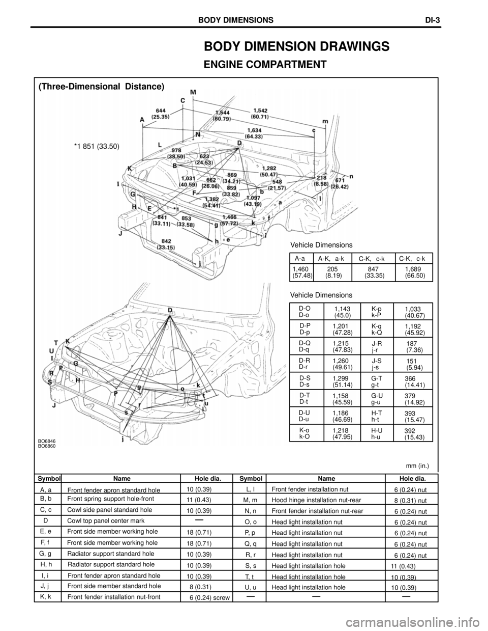
mm (in.)
BO6846
BO6860
1,218
(47.95)392
(15.43)
H-U
h-u
K-o
k-O 1,186
(46.69)
H-T
h-t
393
(15.47)
D-U
D-u 379
(14.92)
G-U
g-u
1,158
(45.59)
D-T
D-t G-T
g-t
366
(14.41)
1,299
(51.14)
D-S
D-s 151
(5.94)
1,260
(49.61)
D-R
D-r
J-S
j-s187
(7.36)
1,215
(47.83)
D-Q
D-q
J-R
j-r1,192
(45.92)
1,201
(47.28)
K-q
k-Q
D-P
D-p 1,033
(40.67)
1,143
(45.0)
K-p
k-P
D-O
D-o
Vehicle Dimensions
1,689
(66.50)
847
(33.35)
205
(8.19)
1,460
(57.48) C-K, c-k
C-K, c-k
A-K, a-k
A-a
Vehicle Dimensions
*1 851 (33.50)
(Three-Dimensional Distance)
Symbol Name Hole dia. Symbol Name Hole dia.
A, a Front fender apron standard hole 10 (0.39)
L, l Front fender installation nut
6 (0.24) nut
B, b Front spring support hole-front
11 (0.43)M, m Hood hinge installation nut-rear
8 (0.31) nut
C, c Cowl side panel standard hole
10 (0.39)N, n Front fender installation nut-rear
6 (0.24) nut
D Cowl top panel center mark
O, oHead light installation nut
6 (0.24) nut
E, e Front side member working hole
18 (0.71)P, pHead light installation nut
6 (0.24) nut
F, f Front side member working hole
18 (0.71)Q, qHead light installation nut
6 (0.24) nut
G, g Radiator support standard hole
10 (0.39)R, rHead light installation nut
6 (0.24) nut
H, h Radiator support standard hole
10 (0.39)S, sHead light installation hole
11 (0.43)
I, i Front fender apron standard hole 10 (0.39)T, t Head light installation hole 10 (0.39)
J, j Front side member standard hole
8 (0.31)U, u Head light installation hole 10 (0.39)
K, k Front fender installation nut-front
6 (0.24) screw
BODY DIMENSION DRAWINGS
ENGINE COMPARTMENT
BODY DIMENSIONSDI-3
WhereEverybodyKnowsYourName
Page 1233 of 4087
BO6847
mm (in.)
(Three-Dimensional Distance)
Hole dia.
18 (0.71)
18 (0.71)
10 (0.39) screw
12 (0.47) screw
Name
Front floor reinforcement standard hole
Rear floor side member standard hole
Suspension member bracket installation nut rear = outer
Transport hook installation nut front = outer
Symbol
L, l
M, m
P, p
Q, q
Hole dia.
6 (0.24) screw
18 (0.71) 13 (0.51)
18 (0.71)
Name
Radiator duct installation nut
Front side member standard holeFront suspension crossmember installation hole
Front side member standard hole
Symbol
A, a
D, d F, f
I, i
UNDER BODY
BODY DIMENSIONSDI-4
WhereEverybodyKnowsYourName
Page 1235 of 4087
BO6847
mm (in.)
(Two-Dimensional Distance)
Hole dia.
18 (0.71) 18 (0.71)
10 (0.39) screw
12 (0.47) screw
Name
Front floor reinforcement standard hole
Rear floor side member standard hole
Suspension member bracket installation nut rear = outer
Transport hook installation nut front = outer
Symbol
L, l
M, m P, p
Q, q
Hole dia.
6 (0.24) screw
18 (0.71)
13 (0.51)
18 (0.71)
Name
Radiator duct installation nut
Front side member standard hole
Front suspension crossmember installation hole
Front side member standard hole
Symbol
A, aD, d F, f
I, i
UNDER BODY (Cont'd)
BODY DIMENSIONSDI-6
WhereEverybodyKnowsYourName
Page 1256 of 4087

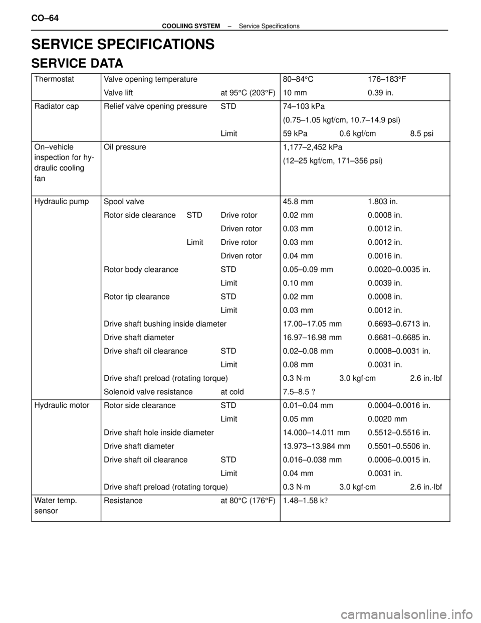
SERVICE SPECIFICATIONS
SERVICE DATA
ThermostatValve opening temperature80±845C176±183 5F
Valve liftat 95 5C (203 5F) 10 mm0.39 in.
Radiator capRelief valve opening pressureSTD74±103 kPa
(0.75±1.05 kgf/cm, 10.7±14.9 psi)
Limit 59 kPa 0.6 kgf/cm 8.5 psi
On±vehicle
itifh
Oil pressure1,177±2,452 kPa
inspection for hy-
draulic cooling(12±25 kgf/cm, 171±356 psi)draulic cooling
fan
fan
Hydraulic pumpSpool valve45.8 mm1.803 in.
Rotor side clearanceSTD Drive rotor 0.02 mm0.0008 in.
Driven rotor 0.03 mm0.0012 in.
Limit Drive rotor 0.03 mm0.0012 in.
Driven rotor 0.04 mm0.0016 in.
Rotor body clearanceSTD 0.05±0.09 mm0.0020±0.0035 in.
Limit 0.10 mm0.0039 in.
Rotor tip clearanceSTD 0.02 mm0.0008 in.
Limit 0.03 mm0.0012 in.
Drive shaft bushing inside diameter17.00±17.05 mm0.6693±0.6713 in.
Drive shaft diameter16.97±16.98 mm0.6681±0.6685 in.
Drive shaft oil clearanceSTD 0.02±0.08 mm0.0008±0.0031 in.
Limit 0.08 mm0.0031 in.
Drive shaft preload (rotating torque)0.3 N Vm 3.0 kgf Vcm 2.6 in. Vlbf
Solenoid valve resistanceat cold 7.5±8.5 �
Hydraulic motorRotor side clearanceSTD0.01±0.04 mm0.0004±0.0016 in.
Limit 0.05 mm0.0020 mm
Drive shaft hole inside diameter14.000±14.011 mm0.5512±0.5516 in.
Drive shaft diameter13.973±13.984 mm0.5501±0.5506 in.
Drive shaft oil clearanceSTD 0.016±0.038 mm0.0006±0.0015 in.
Limit 0.04 mm0.0031 in.
Drive shaft preload (rotating torque)0.3 NVm 3.0 kgf Vcm 2.6 in. Vlbf
Water temp. Resistanceat 80 5C (176 5F)1.48±1.58 k �
sensor
CO±64±
COOLIING SYSTEM Service Specifications
WhereEverybodyKnowsYourName
Page 1257 of 4087

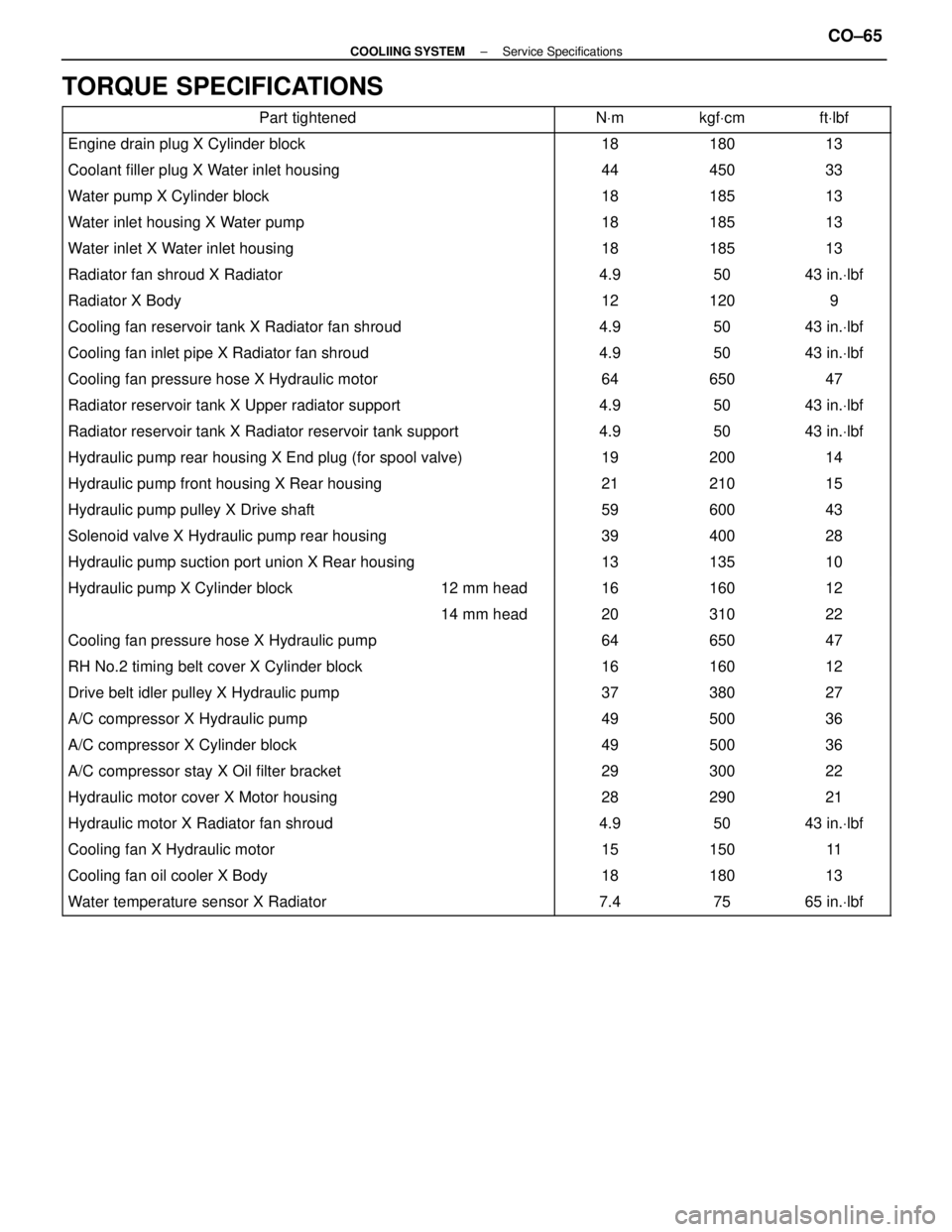
TORQUE SPECIFICATIONS
Part tightenedNVmkgf Vcmft Vlbf
Engine drain plug X Cylinder block1818013
Coolant filler plug X Water inlet housing44450 33
Water pump X Cylinder block18185 13
Water inlet housing X Water pump18185 13
Water inlet X Water inlet housing18185 13
Radiator fan shroud X Radiator4.950 43 in. Vlbf
Radiator X Body12120 9
Cooling fan reservoir tank X Radiator fan shroud4.950 43 in. Vlbf
Cooling fan inlet pipe X Radiator fan shroud4.950 43 in. Vlbf
Cooling fan pressure hose X Hydraulic motor64650 47
Radiator reservoir tank X Upper radiator support4.950 43 in. Vlbf
Radiator reservoir tank X Radiator reservoir tank support4.950 43 in. Vlbf
Hydraulic pump rear housing X End plug (for spool valve)19200 14
Hydraulic pump front housing X Rear housing21210 15
Hydraulic pump pulley X Drive shaft59600 43
Solenoid valve X Hydraulic pump rear housing39400 28
Hydraulic pump suction port union X Rear housing13135 10
����������������� �����������������Hydraulic pump X Cylinder block������ ������12 mm head����� �����16������ ������160������ ������12
����������������� ����������������������� ������14 mm head����� �����20������ ������310������ ������22
������������������\
���� ������������������\
����Cooling fan pressure hose X Hydraulic pump����� �����64������ ������650������ ������47
������������������\
���� ������������������\
����RH No.2 timing belt cover X Cylinder block����� �����16������ ������160������ ������12
������������������\
���� ������������������\
����Drive belt idler pulley X Hydraulic pump����� �����37������ ������380������ ������27
������������������\
���� ������������������\
����A/C compressor X Hydraulic pump����� �����49������ ������500������ ������36
������������������\
���� ������������������\
����A/C compressor X Cylinder block����� �����49������ ������500������ ������36������������������\
���� ������������������\
����A/C compressor stay X Oil filter bracket����� �����29������ ������300������ ������22������������������\
���� ������������������\
����Hydraulic motor cover X Motor housing����� �����28������ ������290������ ������21������������������\
���� �
������������������\
���
������������������\
����Hydraulic motor X Radiator fan shroud
����� �
����
�����4.9
������ �
�����
������50
������ �
�����
������43 in.
Vlbf
������������������\
���� ������������������\
����Cooling fan X Hydraulic motor����� �����15������ ������150������ ������11
������������������\
���� ������������������\
����Cooling fan oil cooler X Body����� �����18������ ������180������ ������13
������������������\
���� ������������������\
����Water temperature sensor X Radiator����� �����7.4������ ������75������ ������65 in. Vlbf
±
COOLIING SYSTEM Service SpecificationsCO±65
WhereEverybodyKnowsYourName
Page 1259 of 4087
DESCRIPTION
This engine utilizes a pressurized forced circulation cooling system which i\
ncludes a hermostat equipped
with a by±pass valve mounted on the inlet side. The cooling system is composed of the water jacket (inside the cylinder bl\
ock and cylinderhead), radiator,
water pump, thermostat, cooling fan, hoses and other components.
OPERATION
CO±2±
COOLIING SYSTEM Description
WhereEverybodyKnowsYourName
Page 1260 of 4087
DESCRIPTION
This engine utilizes a pressurized forced circulation cooling system whi\
ch includes a hermostat equipped
with a by±pass valve mounted on the inlet side. The cooling system is composed of the water jacket (inside the cylinder bl\
ock and cylinderhead), radiator,
water pump, thermostat, cooling fan, hoses and other components.
OPERATION
CO±2±
COOLIING SYSTEM Description
WhereEverybodyKnowsYourName