Page 8 of 4087
 Always replace cotter pins, gaskets, O±rings and oilseals etc. with new ones.
(b) Non±reusable parts are indicated in the component
illustrations by the º �º symbol.")
5. Non±reusable parts(a) Always replace cotter pins, gaskets, O±rings and oilseals etc. with new ones.
(b) Non±reusable parts are indicated in the component
illustrations by the º �º symbol.
6. Precoated parts Precoated parts are bolts and nuts, etc. that are coated with
a seal lock adhesive at the factory.
(a) If a precoated part is retightened, loosened or causedto move in any way, it must be recoated with the
specified adhesive.
(b) Recoating of precoated parts
(1) Clean off the old adhesive from the bolt, nut or threads.
(2) Dry with compressed air.
(3) Apply the specified seal lock adhesive to the bolt or nut threads.
(c) P re co a te d pa rts are in d ica te d in th e co m ponent
illustrations by the º �º symbol.
7. When necessary, use a sealer on gaskets to prevent leaks.
8. Carefully observe all specifications for bolt tightening
torques. Always use a torque wrench.
9. Use of special service tools (SST) and special service materials (SSM) may be required, depending on the nature
of the repair. Be sure to use SST and SSM where specified
and follow the proper work procedure. A list of SST and SSM
can be found in the preparation part at the front of each
section in this manual.
10. When replacing fuses, be sure the new fuse has the correct
amperage rating. DO NOT exceed the rating or use one with
a lower rating.
11. Care must be taken when jacking up and supporting the vehicle. Be sure to lift and support the vehicle at the proper
locations (See page IN±33).
(a) If the vehicle is to be jacked up only at the front or rear end, be sure to block the wheels at the opposite end in
order to ensure safety.
(b) After the vehicle is jacked up, be sure to support it on
stands. It is extremely dangerous to do any work on a
vehicle raised on a jack alone, even for a small job that
can be finished quickly.
±
INTRODUCTION General Repair InstructionsIN±5
WhereEverybodyKnowsYourName
Page 569 of 4087

POWER MIRROR CONTROL
SYSTEM
Description
The Power Miror Control System carries out mirror left/right and up/down ad\
justments electrically when the Mir-
ror Switch is operated. In addition, operation of the Driving Position M\
emory and Return Switches makes it pos-
sible to store the adjusted position in memory and reproduce each adjustment \
when desired. The component
parts of this system and their functions are described in the following table\
.
Parts NameFunction
Outside Rear View
Mirror ECUThe Outside Rear View Mirror ECU is supplied with power from the DOME and RADIO
NO.2 fuses and is connected to the Tilt and Telescopic ECU, Mirror Switch, each
mirror motor and ground.
Rear View Adjustment
SwitchOperation of this switch sends left/right, up/down signals to Outside Re\
ar View Mirror
ECU.
Driving Position Memory
and Return SwitchesMemory and return signals are sent to the ECU via the Tilt and Telescopic ECU.
Mirror MotorThese motors operate on current from the Outside Rear View Mirror ECU, moving
the various parts of the mirror directly.
These sensors send signals about the motor positions to the ECU for stor\
ing in memory
and during return operation.
Left/Right Select SwitchThis switch is used to select operation of the Rear View Adjustment Switch for the
leftor right hand side mirror.
±
BODY ELECTRICAL SYSTEM Power Mirror Control SystemBE±183
WhereEverybodyKnowsYourName
Page 606 of 4087

1RadioRADIO NOT OPERATING WHEN POWER
SWITCH TURNED TO ºONº.
A. Without CD player type
Does radio operate normally when AM or FM
button is pushed?
Check if RADIO NO.1 and RADIO NO.2 fuses
are OK.Is there battery voltage between the following
terminals with connector connected?
� Radio receiver assembly A3±ground
� Radio receiver assembly A4±ground
Is there continuity between the following termi-
nals with connector disconnected?
� Radio receiver assembly A11±ground Radio receiver assembly faulty.Wire harness faulty
Wire Harness faulty.
Replace fuse.
Inspect power switch. Wire harness faulty.
Is there continuity between the following terminals
with connector disconnected?
� Radio receiver assembly B2±power switch 12
� Radio receiver assembly B4±power switch 11
Wire Harness faulty.
Is there battery voltage between the following
terminals with connector connected?
� Radio receiver assembly A11±Power
amplifier A11
Is there continuity between the following termi-
nals with connector disconnected?
� Power amplifier B7±ground
Power amplifier faulty.
BE±220±
BODY ELECTRICAL SYSTEM AUDIO SYSTEM
WhereEverybodyKnowsYourName
Page 607 of 4087

B. with CD player type
Does radio operate normally when AM or FM
button is pushed?
Is there battery positive voltage between the
following terminals with connector connected?
� Radio receiver assembly A3±ground
� Radio receiver assembly A4±ground
Check if RADIO No.1 and RADIO No.2 fuses are OK.
Is therecontinuity between the following termi-
nals with connector disconnected?
� Radio receiver assembly A11±ground Replace fuse.
Wire harness faulty
Radio receiver assembly faulty.
Wire harness faulty.
Wire harness faulty. Inspect power switch.
Wire harness faulty
Is there continuity voltage between the following
terminals with connector connected?
� Radio receiver assembly B2±Power switch 12
� Radio receiver assembly B3±Power switch 11
Is there continuity between the following terminals
with connector disconnected?
� Radio receiver assembly A11±power amplifier A11
Is there continuity between the following terminals
with connector disconnected?
� Radio receiver assembly B7±ground
Power amplifier faulty.
±
BODY ELECTRICAL SYSTEM AUDIO SYSTEMBE±221
WhereEverybodyKnowsYourName
Page 620 of 4087
11Tape playerCASSETTE TAPE CANNOT BE INSERTED
A. without CD player type
Wire harness faulty. Radio receiver assembly faulty.
Is there continuity between the following terminals
with connector connected?
� Radio receiver amplifier A3 ± ground
� Radio receiver amplifier A4 ± ground
Radio receiver assembly faulty.
Is there continuity between the following terminals
with connector disconnected?
�
Radio receiver assembly A7 ± ground Replace fuse.
Wire harness faulty.Remove foreign object.
Is there a foreign object inside tape player?
Is radio operating normally?
Check if RADIO No. 1 and RADIO No. 2 fuses
are OK.
BE±234±
BODY ELECTRICAL SYSTEM AUDIO SYSTEM
WhereEverybodyKnowsYourName
Page 621 of 4087
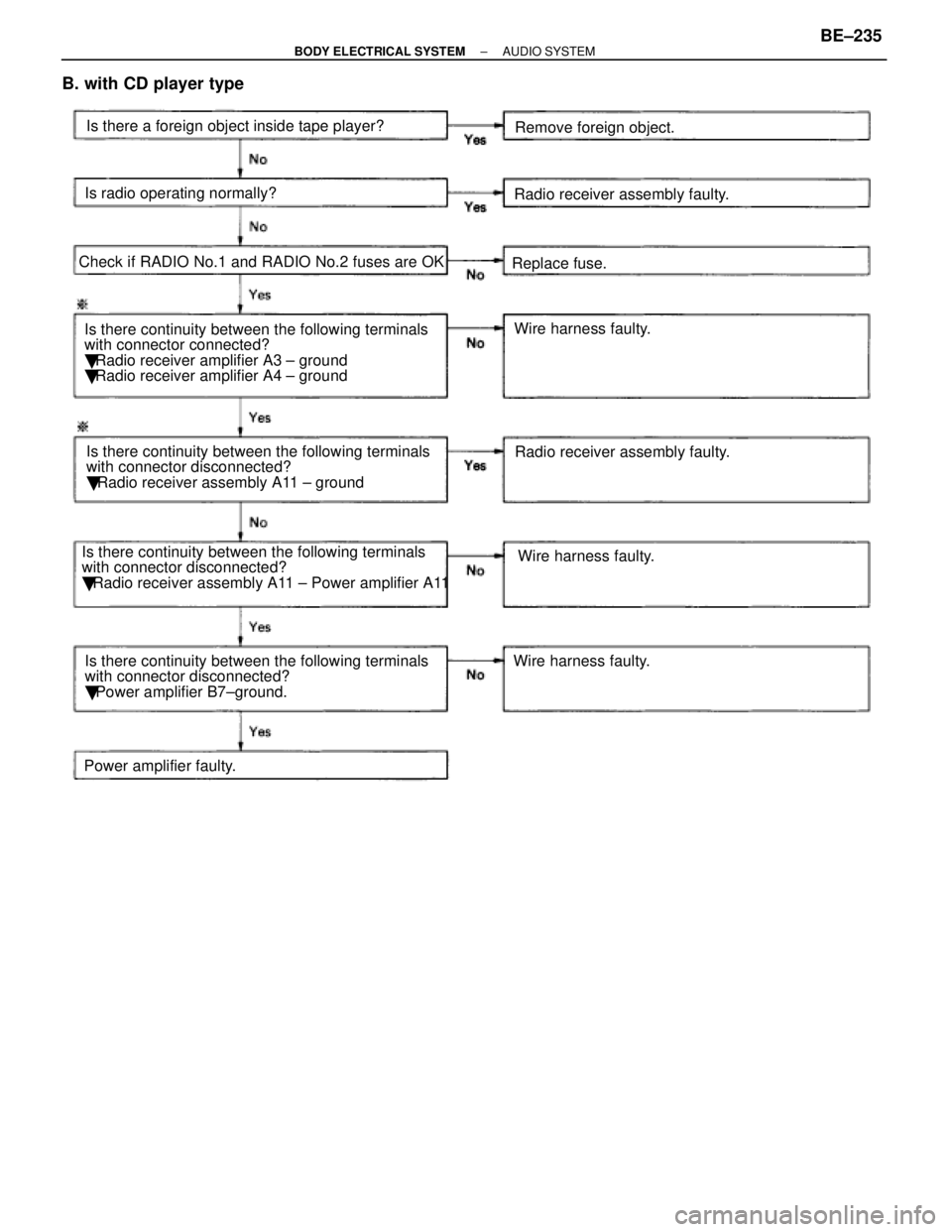
B. with CD player type
Wire harness faulty. Radio receiver assembly faulty.
Is there continuity between the following terminals
with connector connected?
� Radio receiver amplifier A3 ± ground
� Radio receiver amplifier A4 ± ground
Power amplifier faulty. Is there continuity between the following terminals
with connector disconnected?
�
Radio receiver assembly A11 ± ground Replace fuse.
Wire harness faulty.
Remove foreign object.
Is there a foreign object inside tape player?
Is radio operating normally?
Check if RADIO No.1 and RADIO No.2 fuses are OK
Wire harness faulty.Radio receiver assembly faulty.
Is there continuity between the following terminals
with connector disconnected?
� Radio receiver assembly A11 ± Power amplifier A11
Is there continuity between the following terminals
with connector disconnected?
� Power amplifier B7±ground.
±
BODY ELECTRICAL SYSTEM AUDIO SYSTEMBE±235
WhereEverybodyKnowsYourName
Page 622 of 4087
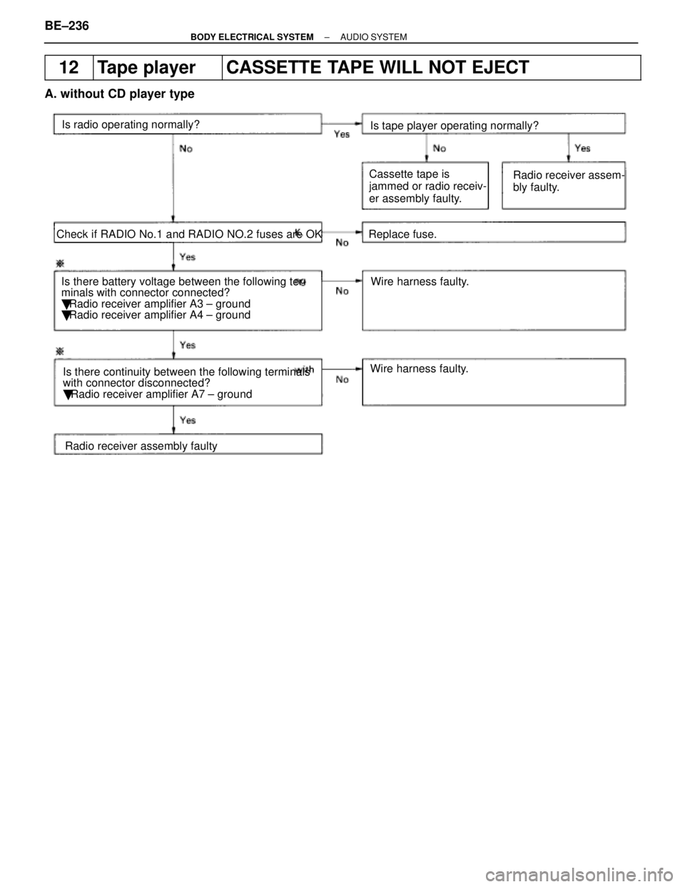
12Tape playerCASSETTE TAPE WILL NOT EJECT
A. without CD player type
Is there battery voltage between the following ter-
minals with connector connected?
� Radio receiver amplifier A3 ± ground
� Radio receiver amplifier A4 ± ground Replace fuse.
Wire harness faulty.
Wire harness faulty.
Is radio operating normally?
Check if RADIO No.1 and RADIO NO.2 fuses are OK Is tape player operating normally?
Radio receiver assembly faulty
Is there continuity between the following terminals
with connector disconnected?
�
Radio receiver amplifier A7 ± ground Cassette tape is
jammed or radio receiv-
er assembly faulty.
Radio receiver assem-
bly faulty.
BE±236±
BODY ELECTRICAL SYSTEM AUDIO SYSTEM
WhereEverybodyKnowsYourName
Page 623 of 4087
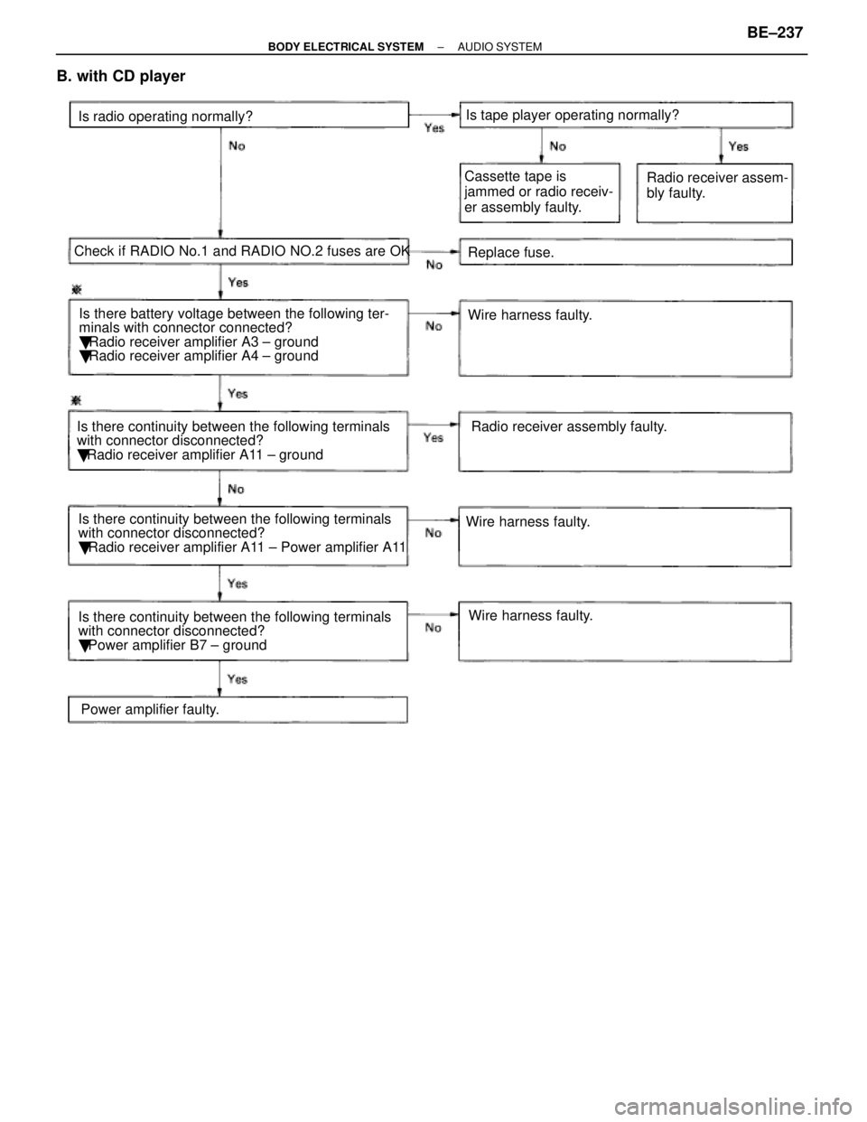
B. with CD player
Is there battery voltage between the following ter-
minals with connector connected?
� Radio receiver amplifier A3 ± ground
� Radio receiver amplifier A4 ± ground Replace fuse.
Wire harness faulty.
Is radio operating normally?
Check if RADIO No.1 and RADIO NO.2 fuses are OK Is tape player operating normally?
Power amplifier faulty.
Is there continuity between the following terminals
with connector disconnected?
�
Radio receiver amplifier A11 ± ground Cassette tape is
jammed or radio receiv-
er assembly faulty.
Radio receiver assem-
bly faulty.
Wire harness faulty. Wire harness faulty.Radio receiver assembly faulty.
Is there continuity between the following terminals
with connector disconnected?
� Radio receiver amplifier A11 ± Power amplifier A11
Is there continuity between the following terminals
with connector disconnected?
� Power amplifier B7 ± ground
±
BODY ELECTRICAL SYSTEM AUDIO SYSTEMBE±237
WhereEverybodyKnowsYourName