Page 1526 of 4087
COMPONENTS FOR ENGINE &
TRANSMISSION SEPERATION AND
ASSEMBLY
EG0BS±0F
ENGINE & TRANSMISSION SEPARATION
EG24X±01
(See Components for Engine & Transmission Separation and
Assembly)
1. REMOVE OIL DIPSTICK GUIDE AND DIPSTICK FOR TRANSMISSION
(a) Remove the bolt.
(b) Pull out the dipstick guide and dipstick from the port of transmission.
(c) Remove the O±ring from the dipstick guide.
2. REMOVE OIL COOLER PIPES FOR TRANSMISSION
(a) Remove the 2 bolts.
(b) Loosen the 2 union nuts, and remove the oil cooler pipes.
EG±150
±
1UZ±FE ENGINE ENGINE MECHANICAL
WhereEverybodyKnowsYourName
Page 1530 of 4087
(b) Disconnect the engine wire clamp from the bracket on thestarter.
(c) Remove the nut, and disconnect the starter wire.
(d) Disconnect the starter connector, and remove the starter.
8. REMOVE KNOCK SENSORS
(a) Disconnect the 2 knock sensor connectors.
(b) Using SST, remove the 2 knock sensors.
SST 09816±30010
9. REMOVE WATER BYPASS PIPE
(a) Remove the 2 bolts.
(b) Pull out the water bypass pipe from the water pump.
(c) Remove the O±ring from the water bypass pipe.
10. REMOVE ENGINE WIRE
(a) Disconnect the following connector: wCrankshaft position sensor connector
w Oil pressure switch connector
w Oil level sensor connector
(b) Remove the 3 bolts and engine wire cover from the LH side of the cylinder block.
(c) Remove the 2 bolts and engine wire.
EG±154
±
1UZ±FE ENGINE ENGINE MECHANICAL
WhereEverybodyKnowsYourName
Page 1531 of 4087
11. REMOVE WATER PUMP
(a) Remove the 5 bolts, 2 stud bolts and nut.
(b) Using a screwdriver remove the water pump by prying theportions between the water pump and cylinder block.
12. REMOVE NO.2 AND NO.1 OIL PANS
(See steps 9 to 14 on pages EG±501 and 502)
13. REMOVE OIL PUMP
(a) Remove the 8 bolts.
(b) Using a screwdriver, remove the oil pump by prying the portions between the oil pump and cylinder block.
(c) Remove the O±ring from the cylinder block.
14. REMOVE GENERATOR BRACKET
Remove the bolt and generator bracket.
15. REMOVE WATER SEAL PLATE
Remove the 2 bolts and seal plate.
±
1UZ±FE ENGINE ENGINE MECHANICALEG±155
WhereEverybodyKnowsYourName
Page 1532 of 4087

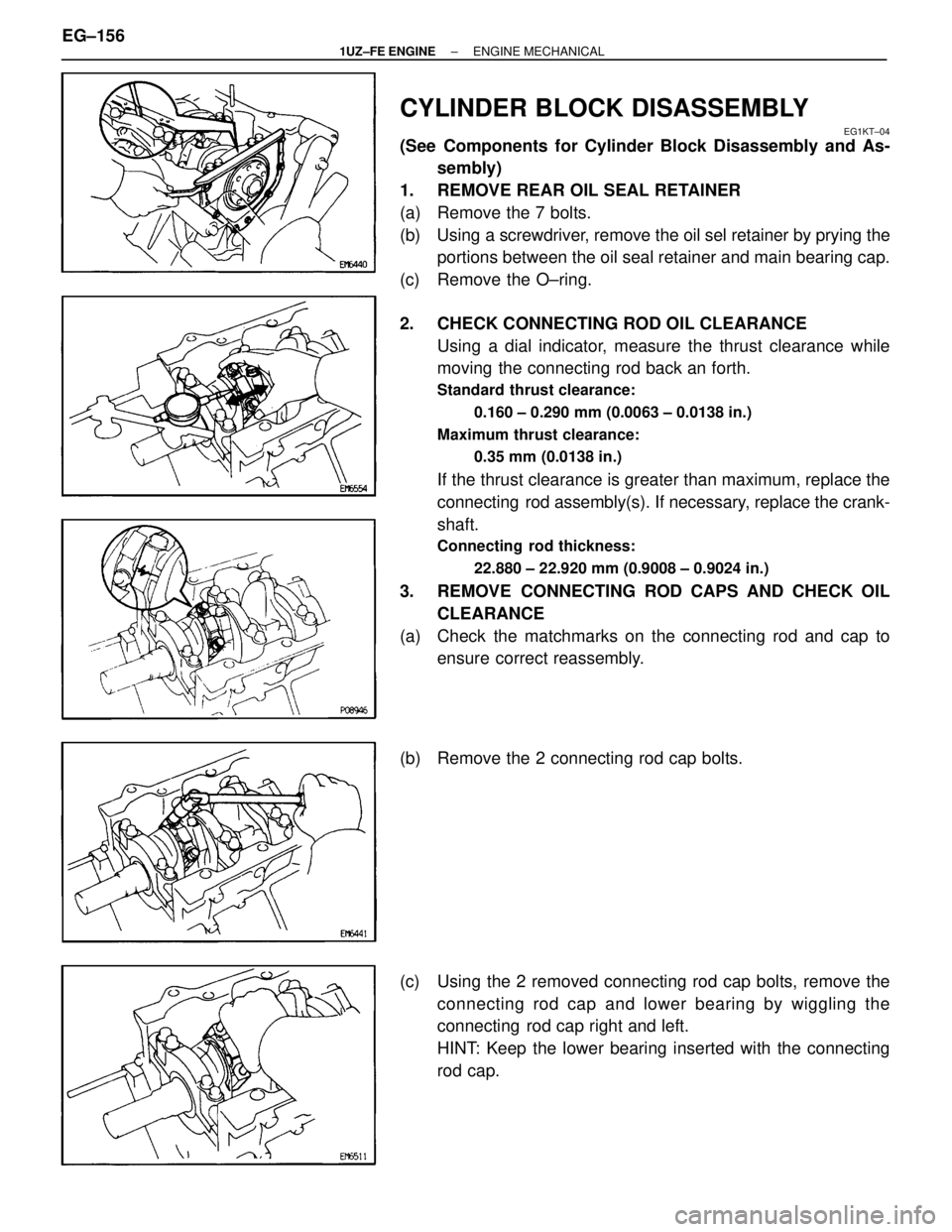
CYLINDER BLOCK DISASSEMBLY
EG1KT±04
(See Components for Cylinder Block Disassembly and As-sembly)
1. REMOVE REAR OIL SEAL RETAINER
(a) Remove the 7 bolts.
(b) Using a screwdriver, remove the oil sel retainer by prying the portions between the oil seal retainer and main bearing cap.
(c) Remove the O±ring.
2. CHECK CONNECTING ROD OIL CLEARANCE Using a dial indicator, measure the thrust clearance while
moving the connecting rod back an forth.
Standard thrust clearance:
0.160 ± 0.290 mm (0.0063 ± 0.0138 in.)
Maximum thrust clearance: 0.35 mm (0.0138 in.)
If the thrust clearance is greater than maximum, replace the
connecting rod assembly(s). If necessary, replace the crank-
shaft.
Connecting rod thickness:
22.880 ± 22.920 mm (0.9008 ± 0.9024 in.)
3. REMOVE CONNECTING ROD CAPS AND CHECK OILCLEARANCE
(a) Check the matchmarks on the connecting rod and cap to ensure correct reassembly.
(b) Remove the 2 connecting rod cap bolts.
(c) Using the 2 removed connecting rod cap bolts, remove the connecting rod cap and lower bearing by wiggling the
connecting rod cap right and left.
HINT: Keep the lower bearing inserted with the connecting
rod cap.
EG±156
±
1UZ±FE ENGINE ENGINE MECHANICAL
WhereEverybodyKnowsYourName
Page 1533 of 4087
(d) Clean the crank pin and bearing.
(e) Check the crank pin and bearing for pitting and scratches.If the crank pin or bearing is damaged, replace the bearings.
If necessary, replace the crankshaft.
(f) Lay a strip of Plastigage across the crank pin.
(g) Install the connecting rod cap with the 2 bolts. (See step 7 on page EG±183)
Torque:
1st 25 N Vm (250 kgf Vcm, 18 ft Vlbf)
2nd Turn 90 5
NOTICE: Do not turn the crankshaft.
(h) Remove the 2 bolts, connecting rod cap and lower bearing. (See procedure (b) and (c) above)
(i) Measure the Plastigage at its widest point.
Standard oil clearance: 0.027 ± 0.053 mm (0.0011 ± 0.0021 in.)
Maximum oil clearance: 0.065 mm (0.0026 in.)
If the oil clearance is greater than maximum, replace the
bearings. If necessary, replace the crankshaft.
±
1UZ±FE ENGINE ENGINE MECHANICALEG±157
WhereEverybodyKnowsYourName
Page 1536 of 4087

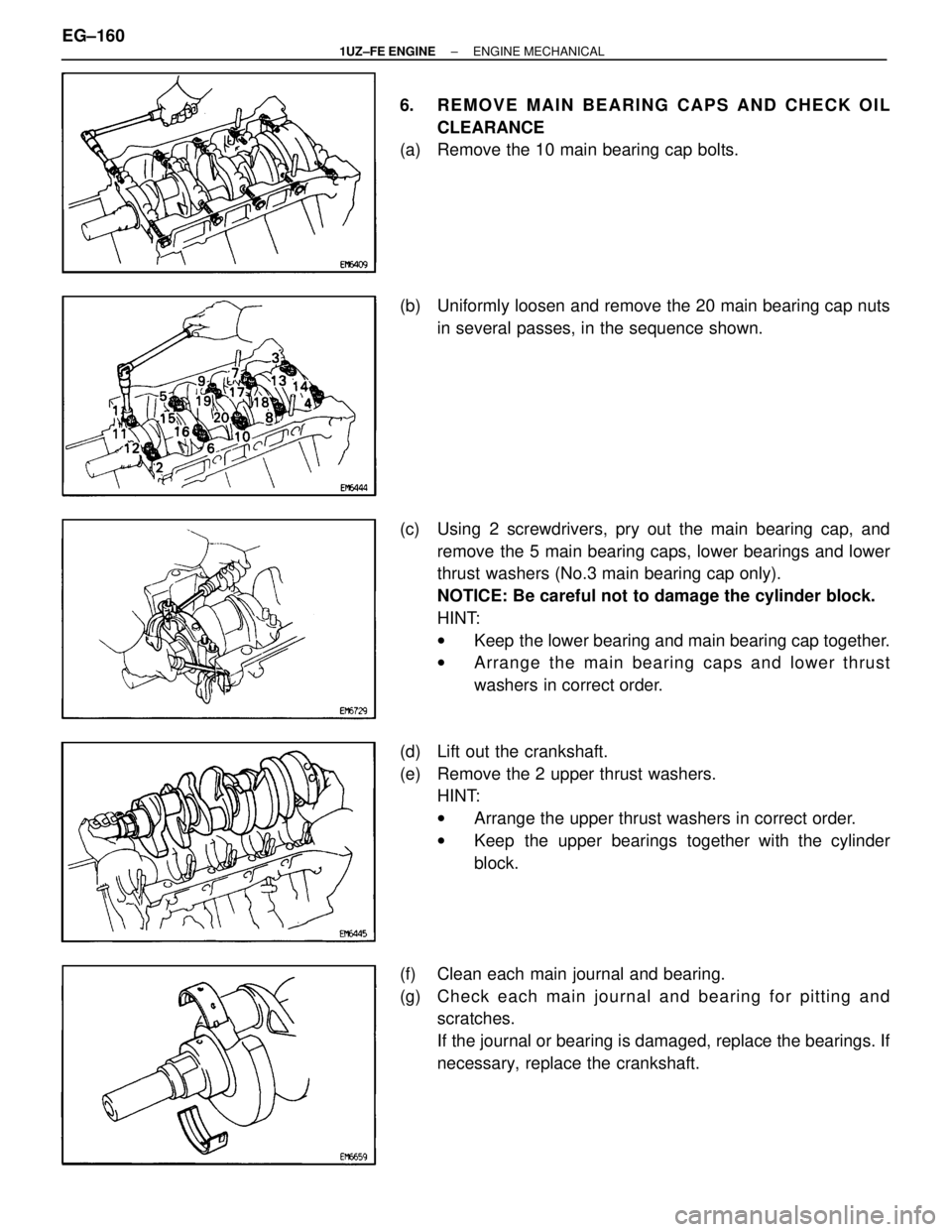
6. REMOVE MAIN BEARING CAPS AND CHECK OILCLEARANCE
(a) Remove the 10 main bearing cap bolts.
(b) Uniformly loosen and remove the 20 main bearing cap nuts
in several passes, in the sequence shown.
(c) Using 2 screwdrivers, pry out the main bearing cap, and remove the 5 main bearing caps, lower bearings and lower
thrust washers (No.3 main bearing cap only).
NOTICE: Be careful not to damage the cylinder block.
HINT:
wKeep the lower bearing and main bearing cap together.
w Arrange the main bearing caps and lower thrust
washers in correct order.
(d) Lift out the crankshaft.
(e) Remove the 2 upper thrust washers. HINT:
wArrange the upper thrust washers in correct order.
w Keep the upper bearings together with the cylinder
block.
(f) Clean each main journal and bearing.
(g) Ch e ck ea ch ma in jo u rn a l an d be a rin g fo r pittin g an d scratches.
If the journal or bearing is damaged, replace the bearings. If
necessary, replace the crankshaft.
EG±160
±
1UZ±FE ENGINE ENGINE MECHANICAL
WhereEverybodyKnowsYourName
Page 1537 of 4087
(h) Install the 5 main bearing caps with the 20 nuts and ten bolts.
Do not install the crankshaft.
(See step 4 on page EG±180)
Torque:
Nut1st 27 N Vm (275 kgf Vcm, 20 ft Vlbf)
2nd Turn 90 5
Bolt 49 N Vm (500 kgf Vcm, 36 ft Vlbf)
(i) Using a cylinder gauge, measure the inside diameter of the
the main bearing.
Bearing inside diameter:
67.026 ± 67.033 mm (2.6388 ± 2.6391 in.)
(j) Using a, micrometer measure the diameter of the mainjournal
Main journal diameter:
66.988 ± 67.000 mm (2.6373 ± 2.6378 in.)
(k) Subtract the main journal diameter measurement from themain bearing inside diameter measurement.
Standard clearance:
0.026 ± 0.045 mm (0.0010 ± 0.0018 in.)
Maximum clearance: 0.055 mm (0.0022 in.)
If the oil clearance is greater than maximum, replace the
bearings. If necessary, replace the crankshaft.
±
1UZ±FE ENGINE ENGINE MECHANICALEG±161
WhereEverybodyKnowsYourName
Page 1543 of 4087
7. IF NECESSARY, REPLACE MAIN BEARING CAP STUDBOLTS
(a) Using the 2 main bearing cap nuts, remove the stud bolt.
(b) Apply a light coat of engine oil on the threads and under
flange of new stud bolts.
(c) Using the 2 main bearing cap nuts, install the stud bolt.
Torque: 15 N Vm (150 kgf Vcm, 11 ft Vlbf)
HINT: Stud bolts come in lengths of 90.0 mm (3.543 in.) and
101.5 mm (3.996 in.). Install the 101.5 mm (3.996 in.) bolts
in inside positions. Install the 90.0 mm (3.543 in.) bolts in out-
side positions.
PISTON AND CONNECTING ROD
DISASSEMBLY
EG0BV±06
1. CHECK FIT BETWEEN PISTON AND PISTON PIN
Try to move the piston back and forth on the piston pin.
If any movement is felt, replace the piston and pin as a set.
2. REMOVE PISTON RINGS
(a) Using a piston ring expander, remove the 2 compression rings.
±
1UZ±FE ENGINE ENGINE MECHANICALEG±167
WhereEverybodyKnowsYourName