Page 1483 of 4087
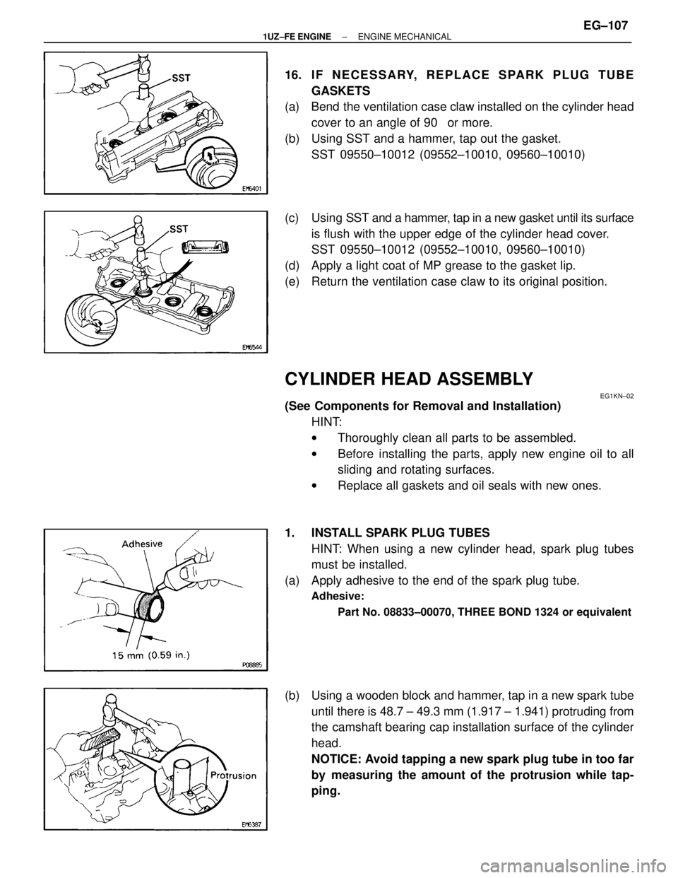
16. IF NECESSARY, REPLACE SPARK PLUG TUBEGASKETS
(a) Bend the ventilation case claw installed on the cylinder head
cover to an angle of 90 � or more.
(b) Using SST and a hammer, tap out the gasket. SST 09550±10012 (09552±10010, 09560±10010)
(c) Using SST and a hammer, tap in a new gasket until its surface
is flush with the upper edge of the cylinder head cover.
SST 09550±10012 (09552±10010, 09560±10010)
(d) Apply a light coat of MP grease to the gasket lip.
(e) Return the ventilation case claw to its original position.
CYLINDER HEAD ASSEMBLY
EG1KN±02
(See Components for Removal and Installation) HINT:
wThoroughly clean all parts to be assembled.
w Before installing the parts, apply new engine oil to all
sliding and rotating surfaces.
w Replace all gaskets and oil seals with new ones.
1. INSTALL SPARK PLUG TUBES HINT: When using a new cylinder head, spark plug tubes
must be installed.
(a) Apply adhesive to the end of the spark plug tube.
Adhesive:
Part No. 08833±00070, THREE BOND 1324 or equivalent
(b) Using a wooden block and hammer, tap in a new spark tubeuntil there is 48.7 ± 49.3 mm (1.917 ± 1.941) protruding from
the camshaft bearing cap installation surface of the cylinder
head.
NOTICE: Avoid tapping a new spark plug tube in too far
by measuring the amount of the protrusion while tap-
ping.
±
1UZ±FE ENGINE ENGINE MECHANICALEG±107
WhereEverybodyKnowsYourName
Page 1484 of 4087
2. INSTALL VALVES
(a) Using SST, push in a new oil seal.SST 09201±41020
(b) Install the following parts: (1) Valve
(2) Spring seat
(3) Valve spring
(4) Spring retainer
(c) Using SST, compress the valve spring and place the 2 keepers around the valve stem.
SST 09202±70010
(d) Using a plastic±faced hammer, lightly tap the valve stem tip to assure proper fit.
3. INSTALL VALVE LIFTERS AND SHIMS
(a) Install the valve lifter and shim.
(b) Check that the valve lifter rotates smoothly by hand.
EG±108
±
1UZ±FE ENGINE ENGINE MECHANICAL
WhereEverybodyKnowsYourName
Page 1487 of 4087
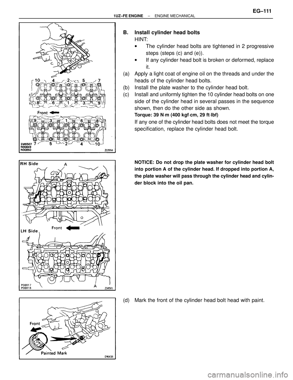
B. Install cylinder head boltsHINT:
wThe cylinder head bolts are tightened in 2 progressive
steps (steps (c) and (e)).
w If any cylinder head bolt is broken or deformed, replace
it.
(a) Apply a light coat of engine oil on the threads and under the
heads of the cylinder head bolts.
(b) Install the plate washer to the cylinder head bolt.
(c) Install and uniformly tig hten the 10 cylinder head bolts on one
side of the cylinder head in several passes in the sequence
shown, then do the other side as shown.
Torque: 39 N Vm (400 kgf Vcm, 29 ft Vlbf)
If any one of the cylinder head bolts does not meet the torque
specification, replace the cylinder head bolt.
NOTICE: Do not drop the plate washer for cylinder head bolt
into portion A of the cylinder head. If dropped into portion A,
the plate washer will pass through the cylinder head and cylin-
der block into the oil pan.
(d) Mark the front of the cylinder head bolt head with paint.
±
1UZ±FE ENGINE ENGINE MECHANICALEG±111
WhereEverybodyKnowsYourName
Page 1489 of 4087
(d) RH Cylinder Head:Install the bearing cap (mark ª11º) in position with the arrow
mark facing rearward.
(e) LH Cylinder Head: Install the bearing cap (mark ª16º) in position with the arrow
mark facing forward.
(f) Install a new seal washer to the bearing cap bolt.
(g) Apply a light coat of engine oil on the threads of the bearing
cap bolt.
(h) Install the 4 bearing cap bolts. Alternately tighten bearing cap bolts.
Torque: 16 N Vm (160 kgf Vcm, 12 ft Vlbf)
HINT: Use silver colored bolts 38 mm (1.50 in.) in length.
6. ASSEMBLE EXHAUST CAMSHAFT
(a) Install the following parts: (1) Camshaft gear spring
(2) Camshaft sub±gear
(3) Wave washer
HINT: Align the pins on the gears with the spring ends.
(b) Using snap ring pliers, install the snap ring.
(c) Mount the hexagon wrench head portion of the camshaft in a vise.
NOTICE: Be careful not to damage the camshaft.
±
1UZ±FE ENGINE ENGINE MECHANICALEG±113
WhereEverybodyKnowsYourName
Page 1491 of 4087
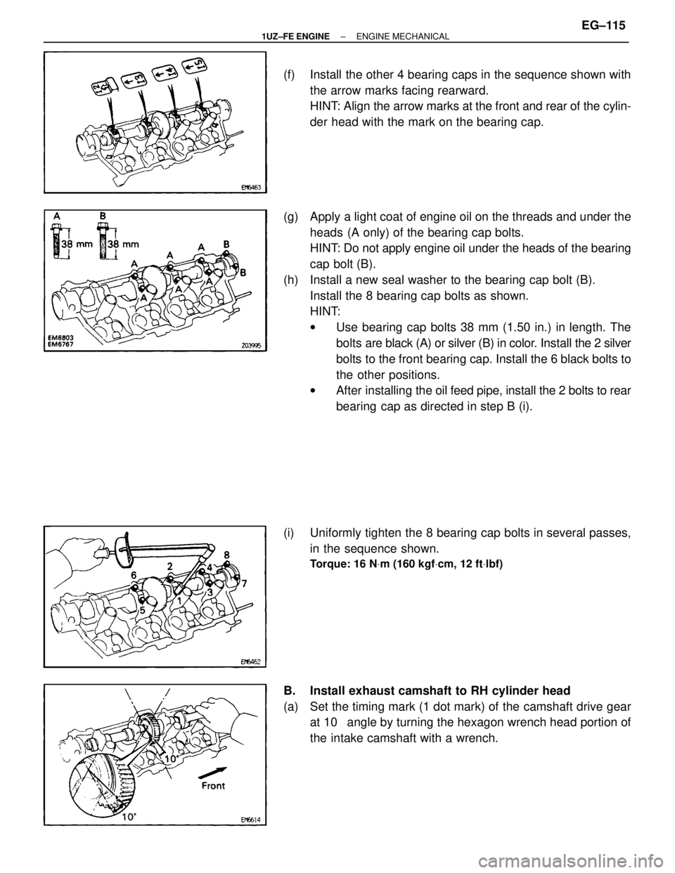
(f) Install the other 4 bearing caps in the sequence shown withthe arrow marks facing rearward.
HINT: Align the arrow marks at the front and rear of the cylin-
der head with the mark on the bearing cap.
(g) Apply a light coat of engine oil on the threads and under the heads (A only) of the bearing cap bolts.
HINT: Do not apply engine oil under the heads of the bearing
cap bolt (B).
(h) Install a new seal washer to the bearing cap bolt (B). Install the 8 bearing cap bolts as shown.
HINT:
wUse bearing cap bolts 38 mm (1.50 in.) in length. The
bolts are black (A) or silver (B) in color. Install the 2 silver
bolts to the front bearing cap. Install the 6 black bolts to
the other positions.
w After installing the oil feed pipe, install the 2 bolts to rear
bearing cap as directed in step B (i).
(i) Uniformly tighten the 8 bearing cap bolts in several passes, in the sequence shown.
Torque: 16 N Vm (160 kgf Vcm, 12 ft Vlbf)
B. Install exhaust camshaft to RH cylinder head
(a) Set the timing mark (1 dot mark) of the camshaft drive gear
at 10 � angle by turning the hexagon wrench head portion of
the intake camshaft with a wrench.
±
1UZ±FE ENGINE ENGINE MECHANICALEG±115
WhereEverybodyKnowsYourName
Page 1492 of 4087
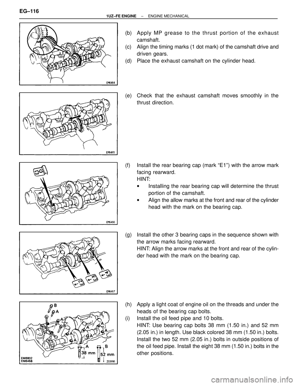
(b) Apply MP grease to the thrust portion of the exhaustcamshaft.
(c) Align the timing marks (1 dot mark) of the camshaft drive and
driven gears.
(d) Place the exhaust camshaft on the cylinder head.
(e) Check that the exhaust camshaft moves smoothly in the thrust direction.
(f) Install the rear bearing cap (mark ªE1º) with the arrow mark facing rearward.
HINT:
wInstalling the rear bearing cap will determine the thrust
portion of the camshaft.
w Align the allow marks at the front and rear of the cylinder
head with the mark on the bearing cap.
(g) Install the other 3 bearing caps in the sequence shown with the arrow marks facing rearward.
HINT: Align the arrow marks at the front and rear of the cylin-
der head with the mark on the bearing cap.
(h) Apply a light coat of engine oil on the threads and under the heads of the bearing cap bolts.
(i) Install the oil feed pipe and 10 bolts.
HINT: Use bearing cap bolts 38 mm (1.50 in.) and 52 mm
(2.05 in.) in length. Use black colored 38 mm (1.50 in.) bolts.
Install the two 52 mm (2.05 in.) bolts in outside positions of
the oil feed pipe. Install the eight 38 mm (1.50 in.) bolts in the
other positions.
EG±116
±
1UZ±FE ENGINE ENGINE MECHANICAL
WhereEverybodyKnowsYourName
Page 1494 of 4087
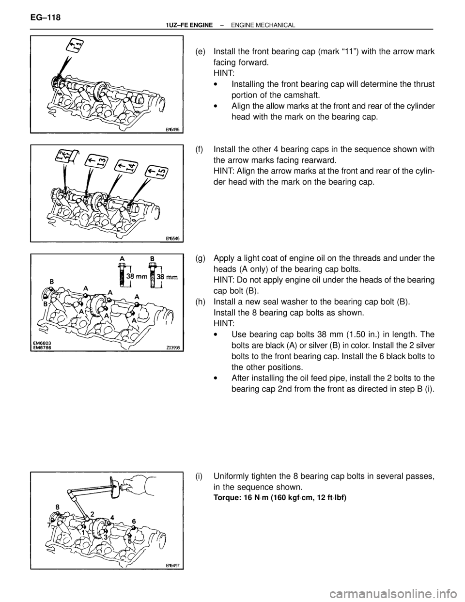
(e) Install the front bearing cap (mark ª11º) with the arrow markfacing forward.
HINT:
wInstalling the front bearing cap will determine the thrust
portion of the camshaft.
w Align the allow marks at the front and rear of the cylinder
head with the mark on the bearing cap.
(f) Install the other 4 bearing caps in the sequence shown with the arrow marks facing rearward.
HINT: Align the arrow marks at the front and rear of the cylin-
der head with the mark on the bearing cap.
(g) Apply a light coat of engine oil on the threads and under the heads (A only) of the bearing cap bolts.
HINT: Do not apply engine oil under the heads of the bearing
cap bolt (B).
(h) Install a new seal washer to the bearing cap bolt (B). Install the 8 bearing cap bolts as shown.
HINT:
wUse bearing cap bolts 38 mm (1.50 in.) in length. The
bolts are black (A) or silver (B) in color. Install the 2 silver
bolts to the front bearing cap. Install the 6 black bolts to
the other positions.
w After installing the oil feed pipe, install the 2 bolts to the
bearing cap 2nd from the front as directed in step B (i).
(i) Uniformly tighten the 8 bearing cap bolts in several passes, in the sequence shown.
Torque: 16 N Vm (160 kgf Vcm, 12 ft Vlbf)
EG±118±
1UZ±FE ENGINE ENGINE MECHANICAL
WhereEverybodyKnowsYourName
Page 1496 of 4087
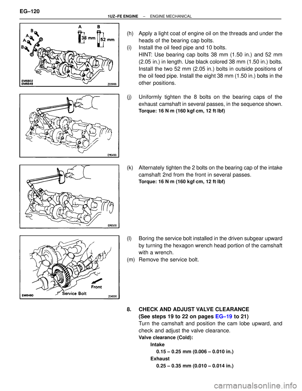
(h) Apply a light coat of engine oil on the threads and under theheads of the bearing cap bolts.
(i) Install the oil feed pipe and 10 bolts.
HINT: Use bearing cap bolts 38 mm (1.50 in.) and 52 mm
(2.05 in.) in length. Use black colored 38 mm (1.50 in.) bolts.
Install the two 52 mm (2.05 in.) bolts in outside positions of
the oil feed pipe. Install the eight 38 mm (1.50 in.) bolts in the
other positions.
(j) Uniformly tighten the 8 bolts on the bearing caps of the exhaust camshaft in several passes, in the sequence shown.
Torque: 16 N Vm (160 kgf Vcm, 12 ft Vlbf)
(k) Alternately ti ghten the 2 bolts on the bearing cap of the intake
camshaft 2nd from the front in several passes.
Torque: 16 N Vm (160 kgf Vcm, 12 ft Vlbf)
(l) Boring the service bolt installed in the driven subgear upward
by turning the hexagon wrench head portion of the camshaft
with a wrench.
(m) Remove the service bolt.
8. CHECK AND ADJUST VALVE CLEARANCE (See steps 19 to 22 on pages EG±19 to 21)
Turn the camshaft and position the cam lobe upward, and
check and adjust the valve clearance.
Valve clearance (Cold):
Intake0.15 ± 0.25 mm (0.006 ± 0.010 in.)
Exhaust 0.25 ± 0.35 mm (0.010 ± 0.014 in.)
EG±120±
1UZ±FE ENGINE ENGINE MECHANICAL
WhereEverybodyKnowsYourName