Page 1446 of 4087
37. INSTALL AIR CONDITIONING (A/C) COMPRESSOR
(a) Install the A/C compressor, compressor stay and groundcable with the nut and 3 bolts.
Torque:
49 NVm (500 kgf Vcm, 36 ft Vlbf) for bolt
29 N Vm (300 kgf Vcm, 22 ft Vlbf) for nut
(b) Connect the A/C compressor connector.
38. INSTALL RADIATOR ASSEMBLY
(a) Install the 2 lower radiator supports to the radiator.
(b) Place the radiator assembly on the body bracket.
(c) Slightly lift the radiator, and connect the 2 oil cooler hoses (for
cooling fan) to the hose clamp on the radiator fan shroud.
(d) Install the upper radiator support with the 2 bolts and screw. Install the 2 upper radiator supports.
Torque: 12 N Vm (120 kgf Vcm, 9 ft Vlbf)
EG±70±
1UZ±FE ENGINE ENGINE MECHANICAL
WhereEverybodyKnowsYourName
Page 1447 of 4087
(e) Connect the following hoses:(1) 2 oil cooler hoses (for cooling fan) to pipes
(2) 2 radiator hoses
(3) 2 oil cooler hoses (for transmission) to radiator
(4) Suction hose to hydraulic pump
(5) Pressure hose to hydraulic pump
(f) Connect the ECT sensor connector (for cooling fan).
(g) Install the ECT sensor wire clamp to the radiator fan shroud.
±
1UZ±FE ENGINE ENGINE MECHANICALEG±71
WhereEverybodyKnowsYourName
Page 1451 of 4087
EG24R±02
CYLINDER HEADS REMOVAL
(See Components for Removal and Installation)
1. DISCONNECT TIMING BELT FROM CAMSHAFT TIMING PULLEYS
(See steps 1 to 29 on pages EG±46 to 54)
2. REMOVE CAMSHAFT TIMING PULLEYS Using SST, remove the bolt and timing pulley. Remove the 2
timing pulleys.
SST 09278±54012
3. REMOVE FAN BRACKET Remove the 2 bolts, 2 nuts and fan bracket.
NOTICE:
w Be careful not to drop anything inside the timing belt
cover.
w Do not allow the belt to come into correct with oil, water
or dust.
4. DISCONNECT POWER STEERING (PS) PUMP FROM
ENGINE
(a) Disconnect the vacuum hose from the air intake chamber.
±
1UZ±FE ENGINE ENGINE MECHANICALEG±75
WhereEverybodyKnowsYourName
Page 1452 of 4087
 Remove the nut and 3 bolts, and disconnect the PS pumpfrom the engine.
5. REMOVE TWC (FRONT)
(a) Remove the 4 bolts holding the pipe support bracket to the transmission.
(b) Remove the 4 bolt")
(b) Remove the nut and 3 bolts, and disconnect the PS pumpfrom the engine.
5. REMOVE TWC (FRONT)
(a) Remove the 4 bolts holding the pipe support bracket to the transmission.
(b) Remove the 4 bolts and nuts holding the front exhaust pipe to the TWC, and remove the pipe support bracket.
(c) Disconnect the front exhaust pipe from the TWC, and remove
the 2 gaskets.
(d) Using a 14 mm deep socket wrench, remove the 3 nuts, TWC
and gasket. Remove the 2 TWC.
6. REMOVE THROTTLE BODY COVER
(a) Disconnect the EVAP hose from the hose clamp.
(b) Remove the cap nut.
(c) Loosen the 2 bolts, and remove the hose clamp and throttle body cover.
7. DISCONNECT CONTROL CABLES FROM THROTTLE BODY
Disconnect the following cables:
(1) Accelerator cable
(2) Transmission throttle control cable
(3) Cruise control actuator cable
8. REMOVE RH IGNITION COIL
(a) Disconnect the ignition coil connector.
(b) Remove the 2 bolts and ignition coil.
EG±76
±
1UZ±FE ENGINE ENGINE MECHANICAL
WhereEverybodyKnowsYourName
Page 1461 of 4087
30. REMOVE OIL DIPSTICK AND GUIDE FORTRANSMISSION
(a) Remove the bolt holding the oil dipstick to the LH cylinder head.
(b) Pull out the dipstick guide together with the dipstick from the oil pan.
(c) Remove the O±ring from the dipstick guide.
31. REMOVE OIL DIPSTICK AND GUIDE FOR ENGINE
32. REMOVE EGR PIPE
(a) Remove the 2 bolts holding the EGR pipe to the RH exhaust pipe.
(b) Remove the EGR pipe and gasket.
33. DISCONNECT ENGINE WIRE FROM CYLINDER HEADS
(a) Remove the 2 bolts, and disconnect the engine wire protector
from the RH cylinder head.
(b) Remove the bolt, and disconnect the ground strap from the RH cylinder head.
(c) Remove the 5 bolts, and disconnect the engine wire protector
from the LH cylinder head.
34. REMOVE ENGINE HANGERS Remove the 2 bolts and engine hanger. Remove the 2 engine
hangers.
±
1UZ±FE ENGINE ENGINE MECHANICALEG±85
WhereEverybodyKnowsYourName
Page 1463 of 4087
(d) Alternately loosen and remove the 2 bearing cap boltsholding the intake camshaft side of the oil feed pipe to the
cylinder head.
(e) Uniformly loosen and remove the 8 bearing cap bolts in several passes, in the sequence shown.
(f) Remove the oil feed pipe, 4 bearing caps and ex haust
camshaft.
B. Remove intake camshaft from RH cylinder head
(a) Remove the rear bearing cap.
(b) Set the timing mark (1 dot mark) of the camshaft drive gear at approx. 45 � angle by turning the hexagon wrench head
portion of the intake camshaft with a wrench.
(c) Uniformly loosen and remove the 8 bearing cap bolts in several passes, in the sequence shown.
(d) Remove the 4 bearing caps, oil seal and intake camshaft.
±
1UZ±FE ENGINE ENGINE MECHANICALEG±87
WhereEverybodyKnowsYourName
Page 1464 of 4087
 Boring the service bolt hole of the driven sub±gear upwardby turning the hexagon wrench head portion of the exhaust
camshaft with a wrench.
(b)")
C. Remove exhaust camshaft from LH cylinder head
(a) Boring the service bolt hole of the driven sub±gear upwardby turning the hexagon wrench head portion of the exhaust
camshaft with a wrench.
(b) Secure the exhaust camshaft sub±gear to drive gear with a service bolt.
Recommended service bolt:6 mm for thread diameter
1.0 mm for thread pitch
16 ± 20 mm (0.63 ± 0.79 in.) for bolt length
HINT: When removing the camshaft, make sure that the tor-
sional spring force of the sub±gear has been eliminated by
the above operation.
(c) Set the timing mark (2 dot marks) of the camshaft drive gear at approx. 15 � angle by turning the hexagon wrench head
portion of the exhaust camshaft with a wrench.
(d) Alternately loosen and remove the 2 bearing cap bolts holding the intake camshaft side of the oil feed pipe to the
cylinder head.
(e) Uniformly loosen and remove the 8 bearing cap bolts in several passes, in the sequence shown.
(f) Remove the oil feed pipe, 4 bearing caps and ex haust
camshaft.
EG±88
±
1UZ±FE ENGINE ENGINE MECHANICAL
WhereEverybodyKnowsYourName
Page 1465 of 4087
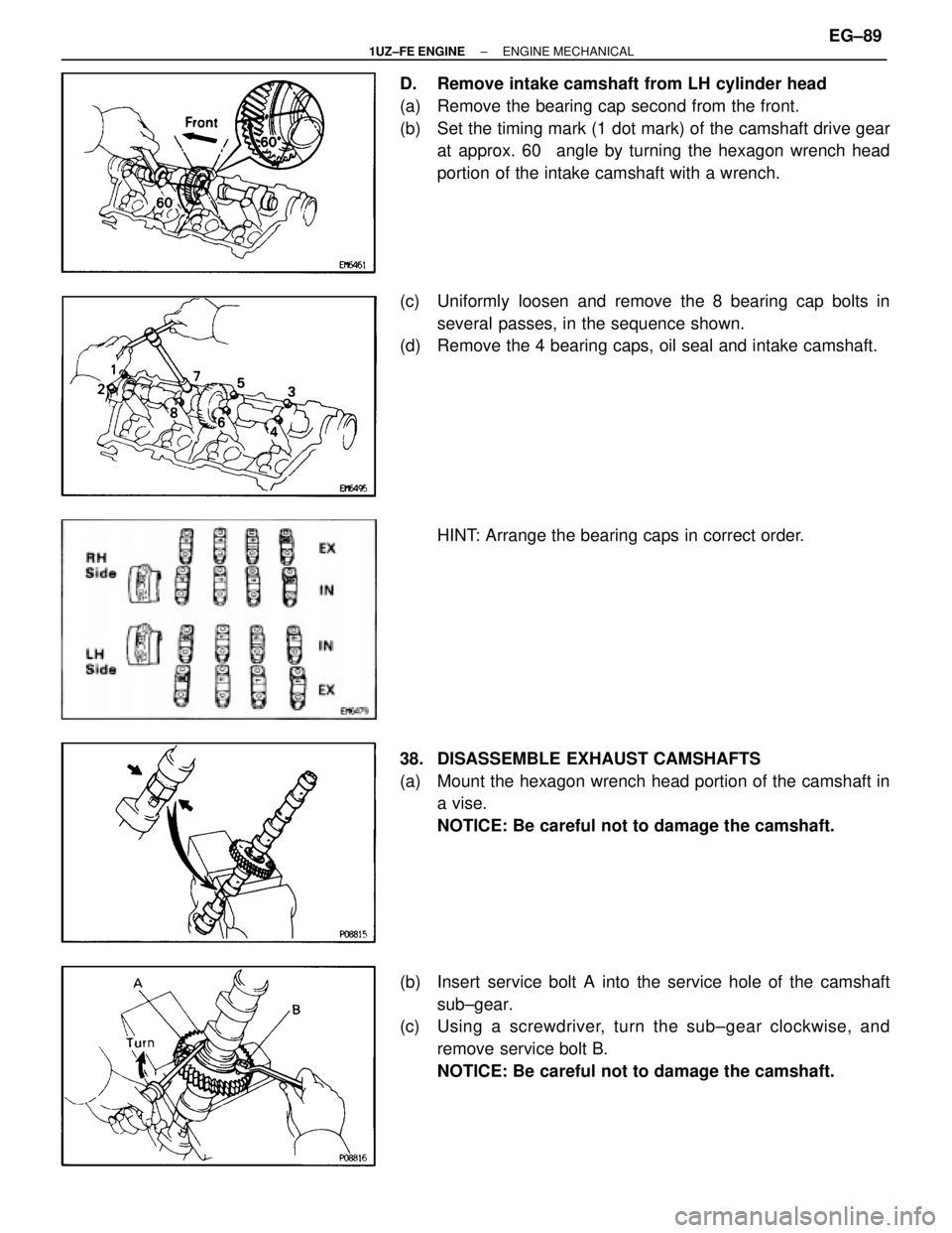
D. Remove intake camshaft from LH cylinder head
(a) Remove the bearing cap second from the front.
(b) Set the timing mark (1 dot mark) of the camshaft drive gearat approx. 60 � angle by turning the hexagon wrench head
portion of the intake camshaft with a wrench.
(c) Uniformly loosen and remove the 8 bearing cap bolts in several passes, in the sequence shown.
(d) Remove the 4 bearing caps, oil seal and intake camshaft.
HINT: Arrange the bearing caps in correct order.
38. DISASSEMBLE EXHAUST CAMSHAFTS
(a) Mount the hexagon wrench head portion of the camshaft in a vise.
NOTICE: Be careful not to damage the camshaft.
(b) Insert service bolt A into the service hole of the camshaft sub±gear.
(c) Using a screwdriver, turn the sub±gear clockwise, and
remove service bolt B.
NOTICE: Be careful not to damage the camshaft.
±
1UZ±FE ENGINE ENGINE MECHANICALEG±89
WhereEverybodyKnowsYourName
 COMPRESSOR
(a) Install the A/C compressor, compressor stay and groundcable with the nut and 3 bolts.
Torque:
49 NVm (500 kgf Vcm, 36 ft Vlbf) for bolt
29 N Vm (30")
 Connect the following hoses:(1) 2 oil cooler hoses (for cooling fan) to pipes
(2) 2 radiator hoses
(3) 2 oil cooler hoses (for transmission) to radiator
(4) Suction hose to hydraulic pump
(5")

1. DISCONNECT TIMING BELT FROM CAMSHAFT TIMING PULLEYS
(See steps 1 to 29 on pages EG±46 to 54)
2. REMOVE CAMSHAFT T")
 Remove the bolt holding the oil dipstick to the LH cylinder head.
(b) Pull out the dipstick guide together with the dipstick from the oil")
 Alternately loosen and remove the 2 bearing cap boltsholding the intake camshaft side of the oil feed pipe to the
cylinder head.
(e) Uniformly loosen and remove the 8 bearing cap bolts in sever")