Page 1553 of 4087
PISTON AND CONNECTING ROD
ASSEMBLY
EG0C1±07
1. ASSEMBLE PISTON AND CONNECTING ROD
(a) Using a small screwdriver, install a new snap ring on one side
of the piston pin hole.
(b) Gradually heat the piston to about 60 �C (140 �F).
(c) Coat the piston pin with engine oil.
(d) Position the piston front mark with respect to the outside mark
on the connecting rod as shown in the diagram.
NOTICE: The installation direction of the piston and con-
necting rod are different for the RH and LH banks. The RH
piston is marked with ªRº, the LH piston with ªLº.
(e) Align the piston pin holes of the piston and connecting rod,
and push in the piston pin with your thumb.
(f) Using a small screwdriver, install a new snap ring on the other
side of the piston pin hole.
±
1UZ±FE ENGINE ENGINE MECHANICALEG±177
WhereEverybodyKnowsYourName
Page 1554 of 4087
2. INSTALL PISTON RINGS
(a) Install the oil ring expander and 2 side rails by hand.
(b) Using a piston ring expander, install the 2 compression ringswith the code mark facing upward.
Code mark:
No.11R or T
No.2 2R or 2T
(c) Position the piston rings so that the ring ends are as shown. NOTICE: Do not align the ring ends.
3. INSTALL BEARINGS
(a) Align the bearing claw with the groove of the connecting rod or connecting cap.
(b) Install the bearings in the connecting rod and connecting rod cap.
EG±178
±
1UZ±FE ENGINE ENGINE MECHANICAL
WhereEverybodyKnowsYourName
Page 1555 of 4087
CYLINDER BLOCK ASSEMBLY
EG1KW±01
(See Components for Cylinder block Disassembly and As-sembly)
HINT:
wThoroughly clean all parts to be assembled.
w Before installing the parts, apply new engine oil to all
sliding and and rotating surfaces.
w Replace all gaskets. O±rings and oil seals with new
parts.
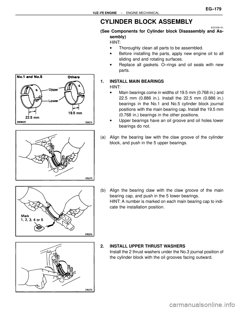
1. INSTALL MAIN BEARINGS HINT:
wMain bearings come in widths of 19.5 mm (0.768 in.) and
22.5 mm (0.886 in.). Install the 22.5 mm (0.886 in.)
bearings in the No.1 and No.5 cylinder block journal
positions with the main bearing cap. Install the 19.5 mm
(0.768 in.) bearings in the other positions.
w Upper bearings have an oil groove and oil holes lower
bearings do not.
(a) Align the bearing law with the claw groove of the cylinder block, and push in the 5 upper bearings.
(b) Align the bearing claw with the claw groove of the main bearing cap, and push in the 5 lower bearings.
HINT: A number is marked on each main bearing cap to indi-
cate the installation position.
2. INSTALL UPPER THRUST WASHERS Install the 2 thrust washers under the No.3 journal position of
the cylinder block with the oil grooves facing outward.
±
1UZ±FE ENGINE ENGINE MECHANICALEG±179
WhereEverybodyKnowsYourName
Page 1557 of 4087
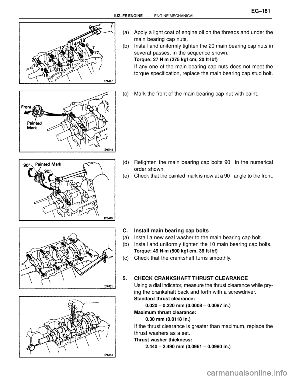
(a) Apply a light coat of engine oil on the threads and under themain bearing cap nuts.
(b) Install and uniformly tighten the 20 main bearing cap nuts in
several passes, in the sequence shown.
Torque: 27 N Vm (275 kgf Vcm, 20 ft Vlbf)
If any one of the main bearing cap nuts does not meet the
torque specification, replace the main bearing cap stud bolt.
(c) Mark the front of the main bearing cap nut with paint.
(d) Retighten the main bearing cap bolts 90 � in the numerical
order shown.
(e) Check that the painted mark is now at a 90 � angle to the front.
C. Install main bearing cap bolts
(a) Install a new seal washer to the main bearing cap bolt.
(b) Install and uniformly tighten the 10 main bearing cap bolts.
Torque: 49 N Vm (500 kgf Vcm, 36 ft Vlbf)
(c) Check that the crankshaft turns smoothly.
5. CHECK CRANKSHAFT THRUST CLEARANCE
Using a dial indi cator, measure the thrust clearance while pry-
ing the crankshaft back and forth with a screwdriver.
Standard thrust clearance:
0.020 ± 0.220 mm (0.0008 ± 0.0087 in.)
Maximum thrust clearance: 0.30 mm (0.0118 in.)
If the thrust clearance is greater than maximum, replace the
thrust washers as a set.
Thrust washer thickness:2.440 ± 2.490 mm (0.0961 ± 0.0980 in.)
±
1UZ±FE ENGINE ENGINE MECHANICALEG±181
WhereEverybodyKnowsYourName
Page 1559 of 4087
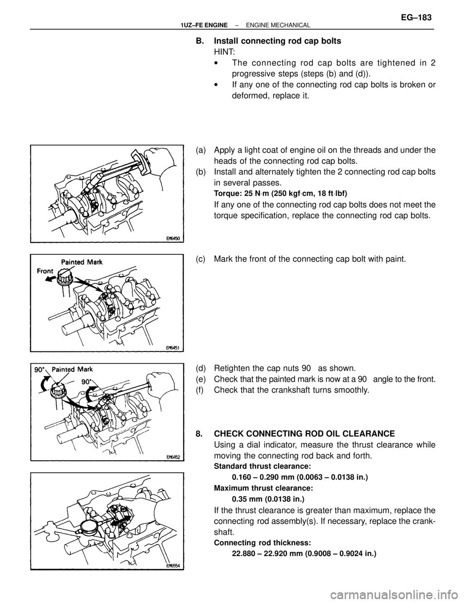
B. Install connecting rod cap boltsHINT:
wThe connecting rod cap bolts are tightened in 2
progressive steps (steps (b) and (d)).
w If any one of the connecting rod cap bolts is broken or
deformed, replace it.
(a) Apply a light coat of engine oil on the threads and under the heads of the connecting rod cap bolts.
(b) Install and alternately tighten the 2 connecting rod cap bolts
in several passes.
Torque: 25 N Vm (250 kgf Vcm, 18 ft Vlbf)
If any one of the connecting rod cap bolts does not meet the
torque specification, replace the connecting rod cap bolts.
(c) Mark the front of the connecting cap bolt with paint.
(d) Retighten the cap nuts 90 � as shown.
(e) Check that the painted mark is now at a 90 � angle to the front.
(f) Check that the crankshaft turns smoothly.
8. CHECK CONNECTING ROD OIL CLEARANCE
Using a dial indicator, measure the thrust clearance while
moving the connecting rod back and forth.
Standard thrust clearance:
0.160 ± 0.290 mm (0.0063 ± 0.0138 in.)
Maximum thrust clearance: 0.35 mm (0.0138 in.)
If the thrust clearance is greater than maximum, replace the
connecting rod assembly(s). If necessary, replace the crank-
shaft.
Connecting rod thickness:22.880 ± 22.920 mm (0.9008 ± 0.9024 in.)
±
1UZ±FE ENGINE ENGINE MECHANICALEG±183
WhereEverybodyKnowsYourName
Page 1560 of 4087
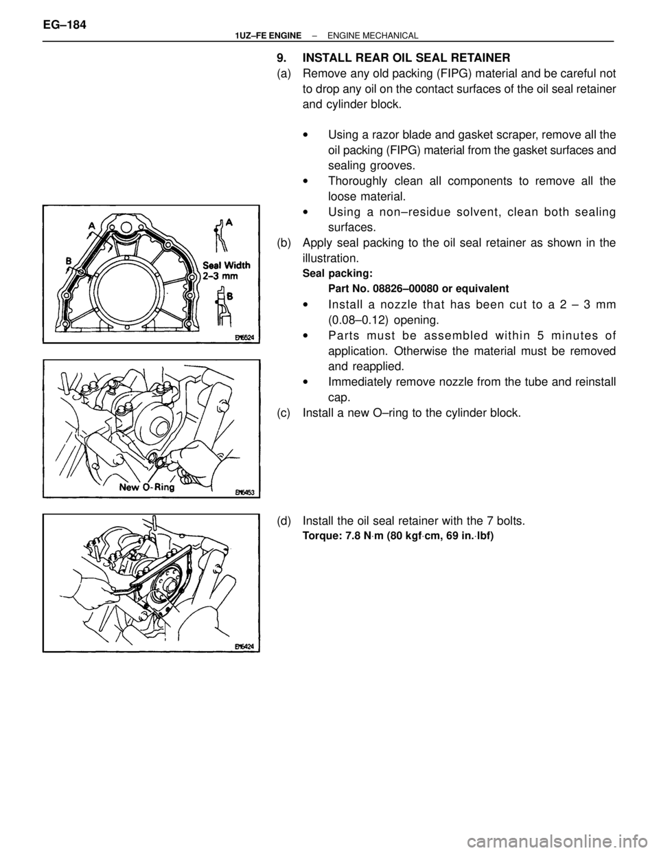
9. INSTALL REAR OIL SEAL RETAINER
(a) Remove any old packing (FIPG) material and be careful notto drop any oil on the contact surfaces of the oil seal retainer
and cylinder block.
wUsing a razor blade and gasket scraper, remove all the
oil packing (FIPG) material from the gasket surfaces and
sealing grooves.
w Thoroughly clean all components to remove all the
loose material.
w Using a non±residue solvent, clean both sealing
surfaces.
(b) Apply seal packing to the oil seal retainer as shown in the illustration.
Seal packing:
Part No. 08826±00080 or equivalent
wIn sta ll a no zzle th a t ha s be e n cu t to a 2 ± 3 mm
(0.08±0.12) opening.
w Parts must be assembled within 5 minutes of
application. Otherwise the material must be removed
and reapplied.
w Immediately remove nozzle from the tube and reinstall
cap.
(c) Install a new O±ring to the cylinder block.
(d) Install the oil seal retainer with the 7 bolts.
Torque: 7.8 N Vm (80 kgf Vcm, 69 in. Vlbf)
EG±184±
1UZ±FE ENGINE ENGINE MECHANICAL
WhereEverybodyKnowsYourName
Page 1561 of 4087
POST ASSEMBLY
EG24Z±01
(See Components for Cylinder Block Prepation of
Disassembly and Post Assembly)
1. INSTALL WATER SEAL PLATE
(a) Remove any old packing (FIPG) material and be careful notto drop any oil on the contact surfaces of the seal plate and
cylinder block.
wUsing a razor blade and gasket scraper remove all the
old packing (FIPG) material from the gasket surfaces
and sealing groove.
w Thoroughly clean all components to remove all the
loose material.
w Using a non±residue solvent, clean both sealing
surfaces.
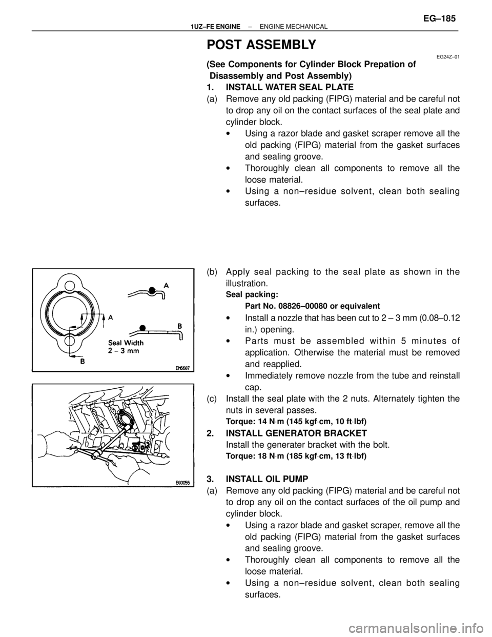
(b) Apply seal packing to the seal plate as shown in the illustration.
Seal packing:
Part No. 08826±00080 or equivalent
wInstall a nozzle that has been cut to 2 ± 3 mm (0.08±0.12
in.) opening.
w Parts must be assembled within 5 minutes of
application. Otherwise the material must be removed
and reapplied.
w Immediately remove nozzle from the tube and reinstall
cap.
(c) Install the seal plate with the 2 nuts. Alternately tighten the
nuts in several passes.
Torque: 14 N Vm (145 kgf Vcm, 10 ft Vlbf)
2. INSTALL GENERATOR BRACKET
Install the generater bracket with the bolt.
Torque: 18 N Vm (185 kgf Vcm, 13 ft Vlbf)
3. INSTALL OIL PUMP
(a) Remove any old packing (FIPG) material and be careful not
to drop any oil on the contact surfaces of the oil pump and
cylinder block.
wUsing a razor blade and gasket scraper, remove all the
old packing (FIPG) material from the gasket surfaces
and sealing groove.
w Thoroughly clean all components to remove all the
loose material.
w Using a non±residue solvent, clean both sealing
surfaces.
±
1UZ±FE ENGINE ENGINE MECHANICALEG±185
WhereEverybodyKnowsYourName
Page 1562 of 4087
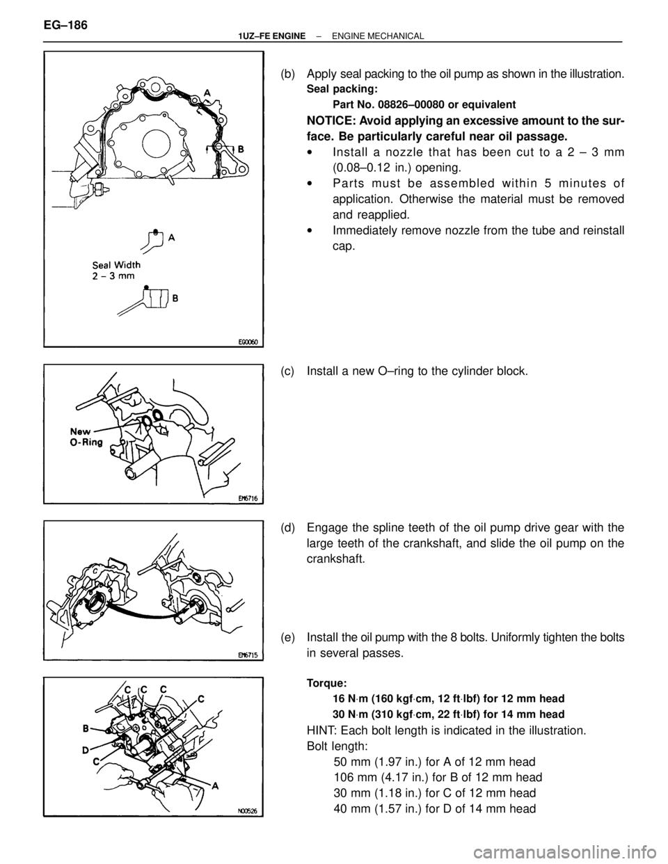
(b) Apply seal packing to the oil pump as shown in the illustration.
Seal packing:
Part No. 08826±00080 or equivalent
NOTICE: Avoid applying an excessive amount to the sur-
face. Be particularly careful near oil passage.
w In sta ll a no zzle th a t ha s be e n cu t to a 2 ± 3 mm
(0.08±0.12 in.) opening.
w Parts must be assembled within 5 minutes of
application. Otherwise the material must be removed
and reapplied.
w Immediately remove nozzle from the tube and reinstall
cap.
(c) Install a new O±ring to the cylinder block.
(d) Engage the spline teeth of the oil pump drive gear with the large teeth of the crankshaft, and slide the oil pump on the
crankshaft.
(e) Install the oil pump with the 8 bolts. Uniformly tighten the bolts
in several passes.
Torque:
16 NVm (160 kgf Vcm, 12 ft Vlbf) for 12 mm head
30 N Vm (310 kgf Vcm, 22 ft Vlbf) for 14 mm head
HINT: Each bolt length is indicated in the illustration.
Bolt length:
50 mm (1.97 in.) for A of 12 mm head
106 mm (4.17 in.) for B of 12 mm head
30 mm (1.18 in.) for C of 12 mm head
40 mm (1.57 in.) for D of 14 mm head
EG±186
±
1UZ±FE ENGINE ENGINE MECHANICAL
WhereEverybodyKnowsYourName