Page 1603 of 4087
HINT:
wKeep the bearings, connecting rod and cap together.
w Arrange the piston and connecting rod assemblies in
correct order.
5. CHECK CRANKSHAFT THRUST CLEARANCE Using a dial indi cator, measure the thrust clearance while pry-
ing the crankshaft back and forth with a screwdriver.
Standard thrust clearance: 0.020±0.220 mm
(0.0008±0.0087 in.)
Maximum thrust clearance: 0.30 mm (0.0118 in.)
If the thrust clearance is greater than maximum, replace the
thrust washers as a set.
Thrust washer thickness: 2.440±2.490 mm (0.0961±0.0980 in.)
6. REMOVE MAIN BEARING CAP AND CHECK OILCLEARANCE
(a) Remove the ten main bearing cap bolts.
(b) Uniformly loosen and remove the twenty main bearingcap nuts in several passes in the sequence shown.
EM±138
±
ENGINE MECHANICAL Cylinder Block
WhereEverybodyKnowsYourName
Page 1605 of 4087
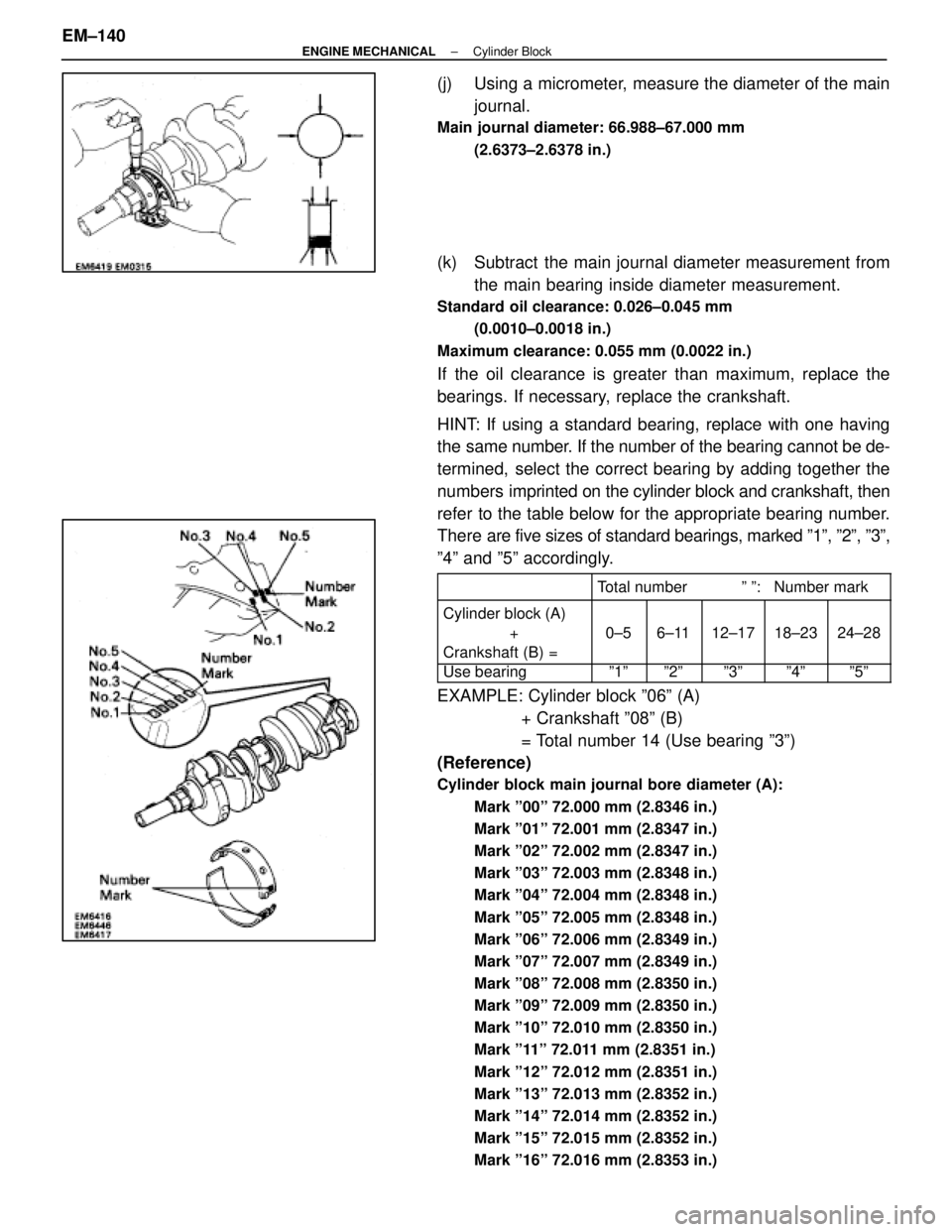
(j) Using a micrometer, measure the diameter of the mainjournal.
Main journal diameter: 66.988±67.000 mm
(2.6373±2.6378 in.)
(k) Subtract the main journal diameter measurement fromthe main bearing inside diameter measurement.
Standard oil clearance: 0.026±0.045 mm
(0.0010±0.0018 in.)
Maximum clearance: 0.055 mm (0.0022 in.)
If the oil clearance is greater than maximum, replace the
bearings. If necessary, replace the crankshaft.
HINT: If using a standard bearing, replace with one having
the same number. If the number of the bearing cannot be de-
termined, select the correct bearing by adding together the
numbers imprinted on the cylinder block and crankshaft, then
refer to the table below for the appropriate bearing number.
There are five sizes of standard bearings, marked º1º, º2º, º3º\
,
º4º and º5º accordingly.
������� �
������
�������
�������������� �
�������������
��������������Total number º º: Number mark
������� �������Cylinder block (A)���� ������� ������ ������� �������� ����
�������+����0±5���6±11���12±17����18±23����24±28������� �������Crankshaft (B) =���� ������� ������ ������� �������� ����
������� �������Use bearing���� ����º1º��� ���º2º��� ���º3º���� ����º4º���� ����º5º
EXAMPLE: Cylinder block º06º (A)
+ Crankshaft º08º (B)
= Total number 14 (Use bearing º3º)
(Reference)
Cylinder block main journal bore diameter (A):
Mark º00º 72.000 mm (2.8346 in.)
Mark º01º 72.001 mm (2.8347 in.)
Mark º02º 72.002 mm (2.8347 in.)
Mark º03º 72.003 mm (2.8348 in.)
Mark º04º 72.004 mm (2.8348 in.)
Mark º05º 72.005 mm (2.8348 in.)
Mark º06º 72.006 mm (2.8349 in.)
Mark º07º 72.007 mm (2.8349 in.)
Mark º08º 72.008 mm (2.8350 in.)
Mark º09º 72.009 mm (2.8350 in.)
Mark º10º 72.010 mm (2.8350 in.)
Mark º11º 72.011 mm (2.8351 in.)
Mark º12º 72.012 mm (2.8351 in.)
Mark º13º 72.013 mm (2.8352 in.)
Mark º14º 72.014 mm (2.8352 in.)
Mark º15º 72.015 mm (2.8352 in.)
Mark º16º 72.016 mm (2.8353 in.)
EM±140±
ENGINE MECHANICAL Cylinder Block
WhereEverybodyKnowsYourName
Page 1609 of 4087
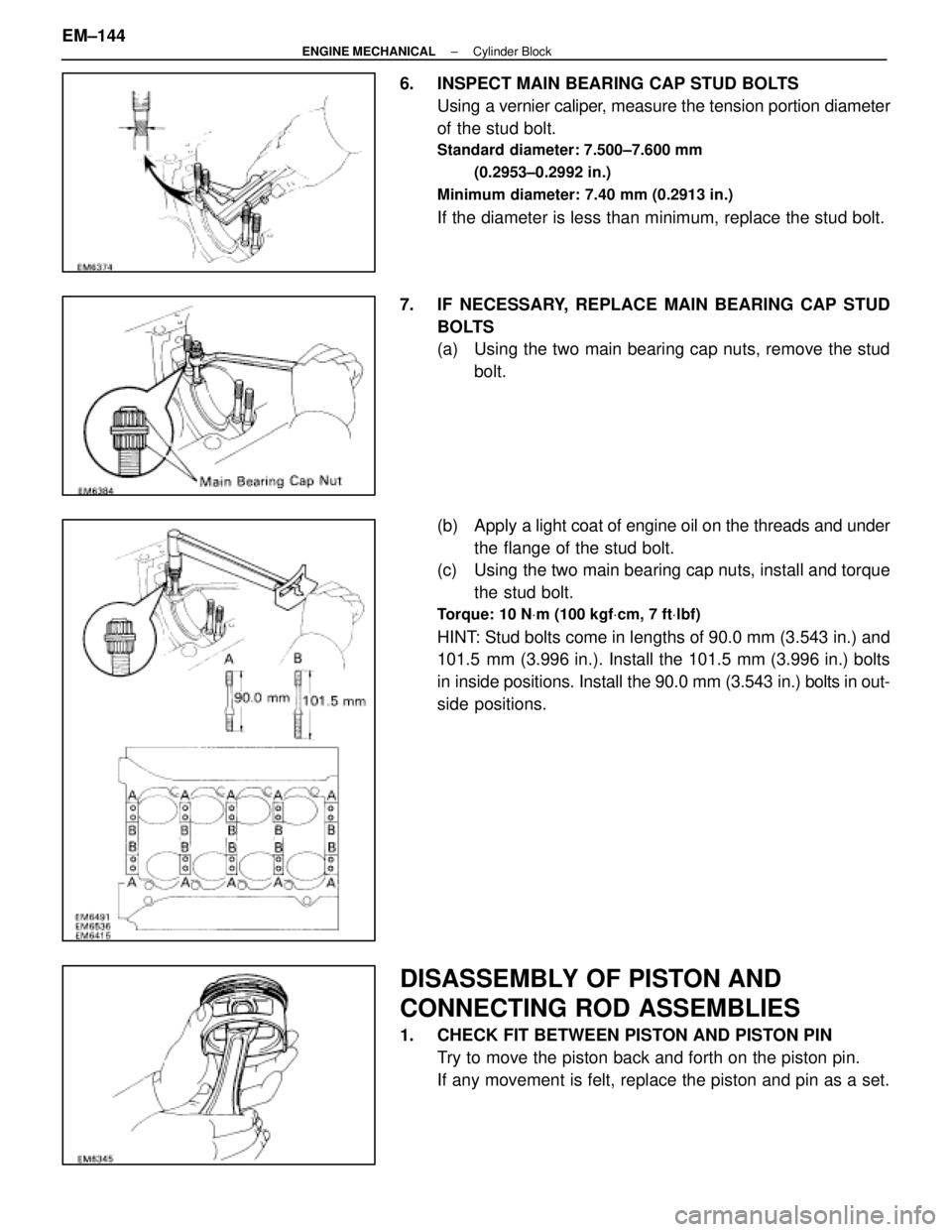
6. INSPECT MAIN BEARING CAP STUD BOLTSUsing a vernier caliper, measure the tension portion diameter
of the stud bolt.
Standard diameter: 7.500±7.600 mm
(0.2953±0.2992 in.)
Minimum diameter: 7.40 mm (0.2913 in.)
If the diameter is less than minimum, replace the stud bolt.
7. IF NECESSARY, REPLACE MAIN BEARING CAP STUD BOLTS
(a) Using the two main bearing cap nuts, remove the studbolt.
(b) Apply a light coat of engine oil on the threads and under
the flange of the stud bolt.
(c) Using the two main bearing cap nuts, install and torque
the stud bolt.
Torque: 10 N Vm (100 kgf Vcm, 7 ft Vlbf)
HINT: Stud bolts come in lengths of 90.0 mm (3.543 in.) and
101.5 mm (3.996 in.). Install the 101.5 mm (3.996 in.) bolts
in inside positions. Install the 90.0 mm (3.543 in.) bolts in out-
side positions.
DISASSEMBLY OF PISTON AND
CONNECTING ROD ASSEMBLIES
1. CHECK FIT BETWEEN PISTON AND PISTON PIN
Try to move the piston back and forth on the piston pin.
If any movement is felt, replace the piston and pin as a set.
EM±144
±
ENGINE MECHANICAL Cylinder Block
WhereEverybodyKnowsYourName
Page 1610 of 4087
2. REMOVE PISTON RINGS(a) U s i n g a p i s t o n r i n g e x pander, remove the two
compression rings.
(b) Remove the two side rails and oil ring expander by hand.
HINT: Arrange the piston rings in correct order only.
3. DISCONNECT CONNECTING ROD FROM PISTON (a) Using a small screwdriver, pry out the two snap rings.
(b) Gradually heat the piston to approx. 60 °C (140 °F).
(c) Using a plastic±face hammer and brass bar, lightly tap out the piston pin and remove the connecting rod.
±
ENGINE MECHANICAL Cylinder BlockEM±145
WhereEverybodyKnowsYourName
Page 1612 of 4087
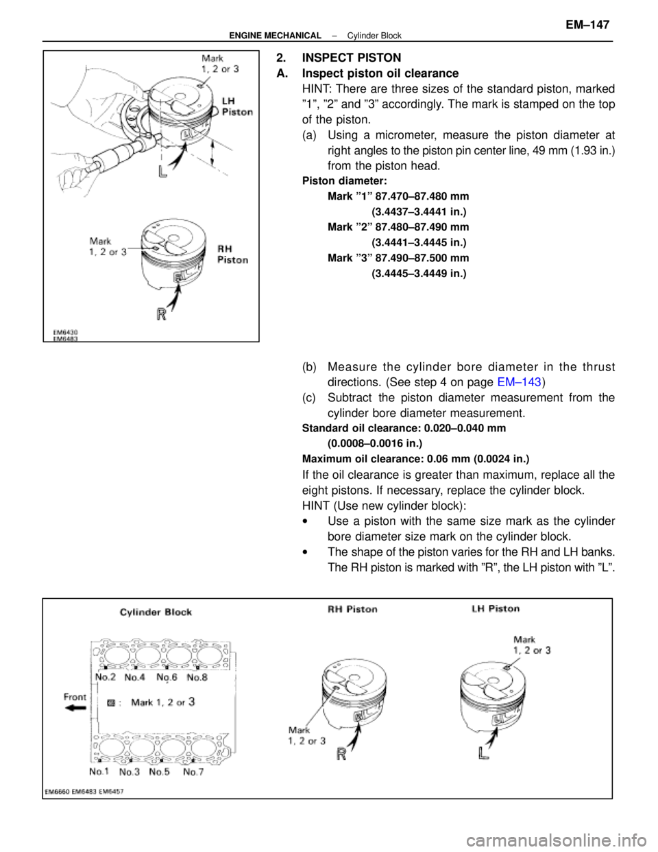
2. INSPECT PISTON
A. Inspect piston oil clearanceHINT: There are three sizes of the standard piston, marked
º1º, º2º and º3º accordingly. The mark is stamped on the top
of the piston.
(a) Using a micrometer, measure the piston diameter atright angles to the piston pin center line, 49 mm (1.93 in.)
from the piston head.
Piston diameter:
Mark º1º 87.470±87.480 mm (3.4437±3.4441 in.)
Mark º2º 87.480±87.490 mm
(3.4441±3.4445 in.)
Mark º3º 87.490±87.500 mm (3.4445±3.4449 in.)
(b) Me a su re th e cyli nder bore diameter in the thrust
directions. (See step 4 on page EM±143)
(c) Subtract the piston diameter measurement from the cylinder bore diameter measurement.
Standard oil clearance: 0.020±0.040 mm
(0.0008±0.0016 in.)
Maximum oil clearance: 0.06 mm (0.0024 in.)
If the oil clearance is greater than maximum, replace all the
eight pistons. If necessary, replace the cylinder block.
HINT (Use new cylinder block):
w Use a piston with the same size mark as the cylinder
bore diameter size mark on the cylinder block.
w The shape of the piston varies for the RH and LH banks.
The RH piston is marked with ºRº, the LH piston with ºLº.
±
ENGINE MECHANICAL Cylinder BlockEM±147
WhereEverybodyKnowsYourName
Page 1613 of 4087
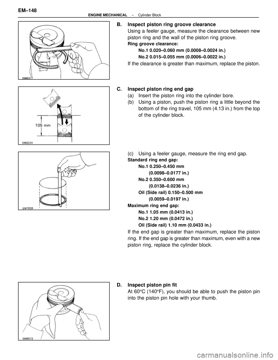
B. Inspect piston ring groove clearanceUsing a feeler gauge, measure the clearance between new
piston ring and the wall of the piston ring groove.
Ring groove clearance:
No.1 0.020±0.060 mm (0.0008±0.0024 in.)
No.2 0.015±0.055 mm (0.0006±0.0022 in.)
If the clearance is greater than maximum, replace the piston.
C. Inspect piston ring end gap (a) Insert the piston ring into the cylinder bore.
(b) Using a piston, push the piston ring a little beyond thebottom of the ring travel, 105 mm (4.13 in.) from the top
of the cylinder block.
(c) Using a feeler gauge, measure the ring end gap.
Standard ring end gap: No.1 0.250±0.450 mm(0.0098±0.0177 in.)
No.2 0.350±0.600 mm (0.0138±0.0236 in.)
Oil (Side rail) 0.150±0.500 mm
(0.0059±0.0197 in.)
Maximum ring end gap: No.1 1.05 mm (0.0413 in.)
No.2 1.20 mm (0.0472 in.)
Oil (Side rail) 1.10 mm (0.0433 in.)
If the end gap is greater than maximum, replace the piston
ring. If the end gap is greater than maximum, even with a new
piston ring, replace the cylinder block.
D. Inspect piston pin fit At 60 5C (140 5F), you should be able to push the piston pin
into the piston pin hole with your thumb.
EM±148
±
ENGINE MECHANICAL Cylinder Block
WhereEverybodyKnowsYourName
Page 1614 of 4087
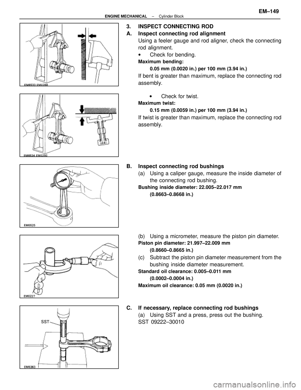
3. INSPECT CONNECTING ROD
A. Inspect connecting rod alignmentUsing a feeler gauge and rod aligner, check the connecting
rod alignment.
wCheck for bending.
Maximum bending:
0.05 mm (0.0020 in.) per 100 mm (3.94 in.)
If bent is greater than maximum, replace the connecting rod
assembly.
w Check for twist.
Maximum twist:
0.15 mm (0.0059 in.) per 100 mm (3.94 in.)
If twist is greater than maximum, replace the connecting rod
assembly.
B. Inspect connecting rod bushings (a) Using a caliper gauge, measure the inside diameter ofthe connecting rod bushing.
Bushing inside diameter: 22.005±22.017 mm
(0.8663±0.8668 in.)
(b) Using a micrometer, measure the piston pin diameter.
Piston pin diameter: 21.997±22.009 mm(0.8660±0.8665 in.)
(c) Subtract the piston pin diameter measurement from thebushing inside diameter measurement.
Standard oil clearance: 0.005±0.011 mm
(0.0002±0.0004 in.)
Maximum oil clearance: 0.05 mm (0.0020 in.)
C. If necessary, replace connecting rod bushings (a) Using SST and a press, press out the bushing.
SST 09222±30010
±
ENGINE MECHANICAL Cylinder BlockEM±149
WhereEverybodyKnowsYourName
Page 1615 of 4087
(b) Align the oil holes of the connecting rod and a newbushing.
(c) Using SST and a press, press in the bushing.
SST 09222±30010
(d) Using a pin hole grinder, hole the bushing to obtain the standard specified clearance (see step B above)
between the bushing and piston pin.
(e) Check the piston pin fit at normal room temperature.
Coat the piston pin with engine oil, and push it into the con-
necting rod with your thumb.
D. Inspect connecting rod bolts Using a vernier caliper, measure the tension portion diameter
of the bolt.
Standard diameter: 7.200±7.300 mm
(0.2835±0.2874 in.)
Minimum diameter: 7.00 mm (0.2756 in.)
If the outside diameter is less than minimum, replace the bolt.
EM±150
±
ENGINE MECHANICAL Cylinder Block
WhereEverybodyKnowsYourName