Page 1626 of 4087

POST ASSEMBLY
(See Components on page EM±131)
1. INSTALL WATER SEAL PLATE (a) Remove any old packing (FIPG) material and be careful
not to drop any oil on the contact surfaces of the seal
plate and cylinder block.
w Using a razor blade and gasket scraper, remove all
the old packing (FIPG) material from the gasket
surfaces and sealing groove.
w Thoroughly clean all components to remove all the
loose material.
w Using a non±residue solvent, clean both sealing
surfaces.
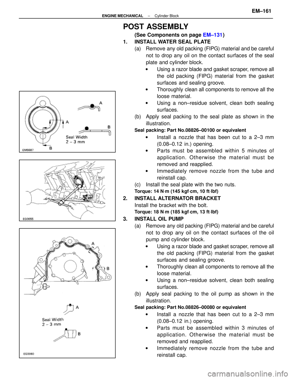
(b) Apply seal packing to the seal plate as shown in the
illustration.
Seal packing: Part No.08826±00100 or equivalent
w Install a nozzle that has been cut to a 2±3 mm
(0.08±0.12 in.) opening.
w Parts must be assembled within 5 minutes of
application. Otherwise the material must be
removed and reapplied.
w Immediately remove nozzle from the tube and
reinstall cap.
(c) Install the seal plate with the two nuts.
Torque: 14 N Vm (145 kgf Vcm, 10 ft Vlbf)
2. INSTALL ALTERNATOR BRACKET
Install the bracket with the bolt.
Torque: 18 N Vm (185 kgf Vcm, 13 ft Vlbf)
3. INSTALL OIL PUMP
(a) Remove any old packing (FIPG) material and be carefulnot to drop any oil on the contact surfaces of the oil
pump and cylinder block.
w Using a razor blade and gasket scraper, remove all
the old packing (FIPG) material from the gasket
surfaces and sealing groove.
w Thoroughly clean all components to remove all the
loose material.
w Using a non±residue solvent, clean both sealing
surfaces.
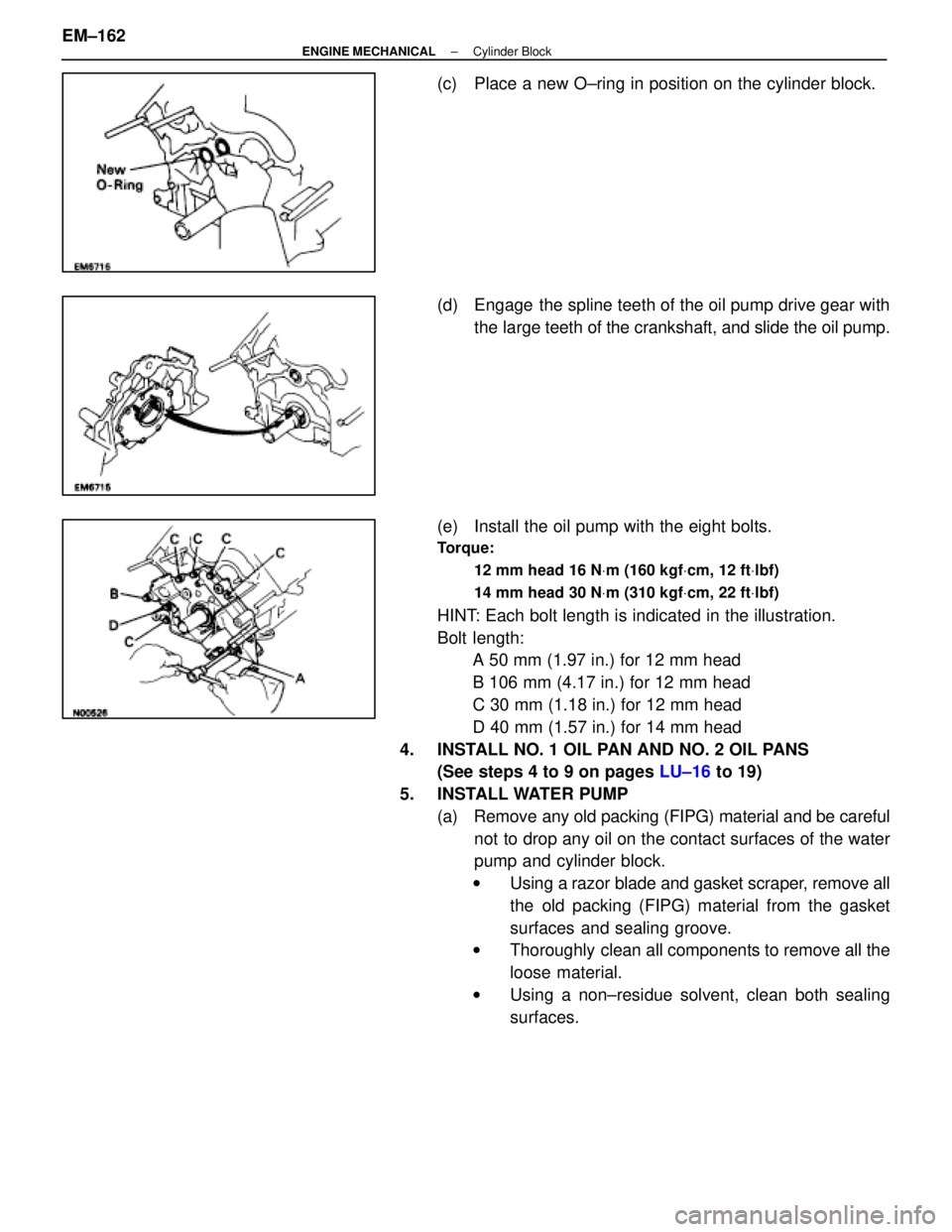
(b) Apply seal packing to the oil pump as shown in the
illustration.
Seal packing: Part No.08826±00080 or equivalent
w Install a nozzle that has been cut to a 2±3 mm
(0.08±0.12 in.) opening.
w Parts must be assembled within 3 minutes of
application. Otherwise the material must be
removed and reapplied.
w Immediately remove nozzle from the tube and
reinstall cap.
±
ENGINE MECHANICAL Cylinder BlockEM±161
WhereEverybodyKnowsYourName
Page 1627 of 4087

(c) Place a new O±ring in position on the cylinder block.
(d) Engage the spline teeth of the oil pump drive gear withthe large teeth of the crankshaft, and slide the oil pump.
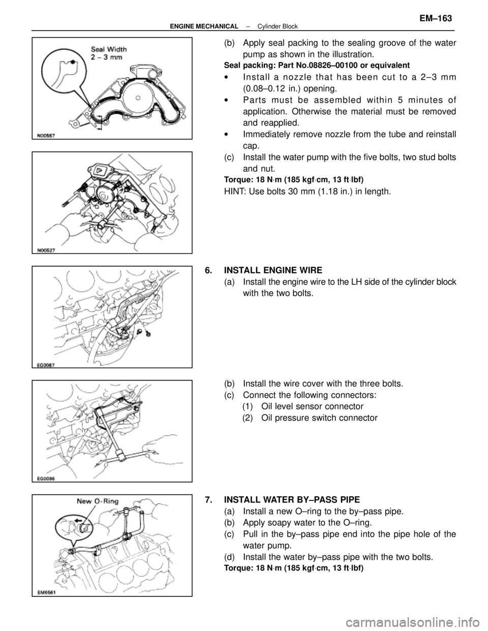
(e) Install the oil pump with the eight bolts.
Torque: 12 mm head 16 N Vm (160 kgf Vcm, 12 ft Vlbf)
14 mm head 30 N Vm (310 kgf Vcm, 22 ft Vlbf)
HINT: Each bolt length is indicated in the illustration.
Bolt length:
A 50 mm (1.97 in.) for 12 mm head
B 106 mm (4.17 in.) for 12 mm head
C 30 mm (1.18 in.) for 12 mm head
D 40 mm (1.57 in.) for 14 mm head
4. INSTALL NO. 1 OIL PAN AND NO. 2 OIL PANS (See steps 4 to 9 on pages LU±16 to 19)
5. INSTALL WATER PUMP (a) Remove any old packing (FIPG) material and be carefulnot to drop any oil on the contact surfaces of the water
pump and cylinder block.
w Using a razor blade and gasket scraper, remove all
the old packing (FIPG) material from the gasket
surfaces and sealing groove.
w Thoroughly clean all components to remove all the
loose material.
w Using a non±residue solvent, clean both sealing
surfaces.
EM±162
±
ENGINE MECHANICAL Cylinder Block
WhereEverybodyKnowsYourName
Page 1628 of 4087

(b) Apply seal packing to the sealing groove of the waterpump as shown in the illustration.
Seal packing: Part No.08826±00100 or equivalent
wInstall a nozzle that has been cut to a 2±3 mm
(0.08±0.12 in.) opening.
w Parts must be assembled within 5 minutes of
application. Otherwise the material must be removed
and reapplied.
w Immediately remove nozzle from the tube and reinstall
cap.
(c) Install the water pump with the five bolts, two stud bolts and nut.
Torque: 18 N Vm (185 kgf Vcm, 13 ft Vlbf)
HINT: Use bolts 30 mm (1.18 in.) in length.
6. INSTALL ENGINE WIRE (a) Install the engine wire to the LH side of the cylinder block
with the two bolts.
(b) Install the wire cover with the three bolts.
(c) Connect the following connectors: (1) Oil level sensor connector
(2) Oil pressure switch connector
7. INSTALL WATER BY±PASS PIPE (a) Install a new O±ring to the by±pass pipe.
(b) Apply soapy water to the O±ring.
(c) Pull in the by±pass pipe end into the pipe hole of thewater pump.
(d) Install the water by±pass pipe with the two bolts.
Torque: 18 N Vm (185 kgf Vcm, 13 ft Vlbf)
±
ENGINE MECHANICAL Cylinder BlockEM±163
WhereEverybodyKnowsYourName
Page 1630 of 4087
12. INSTALL CYLINDER HEADS(See pages EM±92 to 115)
13. INSTALL TIMING PULLEYS AND BELT (See pages EM±48 to 57)
14. REMOVE ENGINE STAND FROM ENGINE
15. INSTALL DRIVE PLATE (a) Apply adhesive to two or three threads of the mountingbolt end.
Adhesive: Part No.08833±00070, THREE BOND 1324 or equiva-
lent
(b) Install the front spacer, drive plate and rear spacer on the crankshaft.
(c) Install and uniformly tighten the eight mounting bolts in
several passes in the sequence shown.
Torque: 98 N Vm (1,000 kgf Vcm, 72 ft Vlbf)
ASSEMBLY OF ENGINE AND
TRANSMISSION
(See Components on page EM±129)
1. ASSEMBLE ENGINE AND TRANSMISSION (See AT section)
2. INSTALL OIL COOLER PIPE (a) Temporarily install the two mounting bolts.
(b) Connect the two oil cooler pipes to the unions on thetransmission. Tighten the union nuts.
Torque: 34 N Vm (350 kgf Vcm, 25 ft Vlbf)
±
ENGINE MECHANICAL Cylinder BlockEM±165
WhereEverybodyKnowsYourName
Page 1631 of 4087
3. INSTALL DIPSTICK GUIDE FOR TRANSMISSION(a) Install a new O±ring to the dipstick guide.
(b) Apply soapy water to the O±ring.
(c) Connect the dipstick guide end to the tube of the oil pan,
and install the dipstick guide with the bolt.
(d) Install the dipstick.
4. CONNECT ENGINE WIRE TO TRANSMISSION (a) Connect the following connectors:(1) O/D direct clutch speed sensor connector
(2) No.1 speed sensor connector
(3) No.2 speed sensor connector
(4) Neutral start switch connector
(b) Install the five wire clamps to the brackets on the transmission.
EM±166±
ENGINE MECHANICAL Cylinder Block
WhereEverybodyKnowsYourName
Page 1638 of 4087
17. INSTALL PS TUBESInstall the PS tube clamp with the bolt.
18. INSTALL ALTERNATOR (a) Install the alternator and A/T oil cooler pipe bracket withthe bolt and nut.
Torque: 37 N Vm (380 kgf Vcm, 27 ft Vlbf)
(b) Connect the alternator connector.
(c) Connect the alternator wire with the nut and cap.
19. INSTALL WIRE CLAMP (FOR ALTERNATOR) AND VSV (FOR EVAP SYSTEM)
(a) Install the wire clamp to the VSV bracket.
(b) Install the VSV with the two bolts.
20. CONNECT PS SOLENOID VALVE CONNECTOR
21. CONNECT ENGINE WIRE CONNECTORS
22. CONNECT THEFT DETERRENT HORN CONNECTOR
23. INSTALL GROUND CABLE TO BODY
±
ENGINE MECHANICAL Cylinder BlockEM±173
WhereEverybodyKnowsYourName
Page 1640 of 4087
(3) Two oil cooler hoses (for A/T) to radiator
(4) Two radiator hoses
(5) Two oil cooler hoses (for cooling fan) to pipes
(f) Connect the water temperature sensor connector.
(g) Install the wire clamp (for water temperature sensor) to the radiator fan shrould.
26. INSTALL RADIATOR RESERVOIR TANK (a) Install the reservoir tank to the reservoir tank bracket.
(b) Install the reservoir tank bracket with the two bolts.
±
ENGINE MECHANICAL Cylinder BlockEM±175
WhereEverybodyKnowsYourName
Page 1642 of 4087

31. INSTALL THROTTLE BODY COVERInstall the throttle body cover and hose clamp with the two
bolts and cap nut.
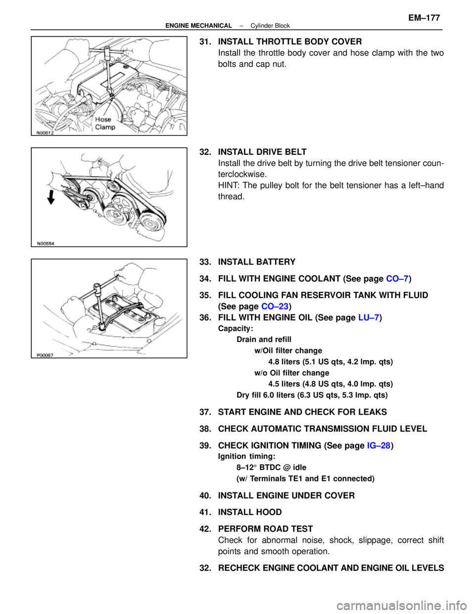
32. INSTALL DRIVE BELT Install the drive belt by turning the drive belt tensioner coun-
terclockwise.
HINT: The pulley bolt for the belt tensioner has a left±hand
thread.
33. INSTALL BATTERY
34. FILL WITH ENGINE COOLANT (See page CO±7)
35. FILL COOLING FAN RESERVOIR TANK WITH FLUID (See page CO±23)
36. FILL WITH ENGINE OIL (See page LU±7)
Capacity:
Drain and refill
w/Oil filter change4.8 liters (5.1 US qts, 4.2 lmp. qts)
w/o Oil filter change 4.5 liters (4.8 US qts, 4.0 lmp. qts)
Dry fill 6.0 liters (6.3 US qts, 5.3 lmp. qts)
37. START ENGINE AND CHECK FOR LEAKS
38. CHECK AUTOMATIC TRANSMISSION FLUID LEVEL
39. CHECK IGNITION TIMING (See page IG±28)
Ignition timing:
8±125 BTDC @ idle
(w/ Terminals TE1 and E1 connected)
40. INSTALL ENGINE UNDER COVER
41. INSTALL HOOD
42. PERFORM ROAD TEST Check for abnormal noise, shock, slippage, correct shift
points and smooth operation.
32. RECHECK ENGINE COOLANT AND ENGINE OIL LEVELS
±
ENGINE MECHANICAL Cylinder BlockEM±177
WhereEverybodyKnowsYourName