Page 1664 of 4087
 Remove any oil packing (FIPG) material.
(b) Apply seal packing to the cylinder head as shown in theillustration.
Seal packing: Part No.")
13. REINSTALL NO. 3, NO. 1 AND NO. 2 CYLINDER HEADCOVERS
(a) Remove any oil packing (FIPG) material.
(b) Apply seal packing to the cylinder head as shown in theillustration.
Seal packing: Part No. 08826±00080 or equivalent
(c) Install the gaskets to the No. 1 and No. 2 cylinder headcovers.
(d) Install the cylinder head cover with the 12 bolts and four
nuts.
Torque: 5.4 N Vm (55 kgf Vcm, 48 in. Vlbf)
14. R E C O N N E C T H I G H ± T E N S I O N C O R D S TO S PA R K
PLUGS
(a) Connect the high±tension cord to the spark plug.
HINT: The No. 4 high±tension cord must be raised 10 5 from
the perpendicular line.
(b) Connect the two high±tension cord clamps to the No. 3 cylinder head cover.
(c) Install the high±tension cord clamp with the bolt.
15. REINSTALL CYLINDER HEAD REAR COVER AND NO. 3 TIMING BELT COVER
(a) Using a 5 mm hexagon wrench, install the cylinder head
rear cover and No. 3 timing belt cover with the ten bolts.
(b) Install the oil filler cap.
±
ENGINE MECHANICAL Engine Tune±UpEM±17
WhereEverybodyKnowsYourName
Page 1667 of 4087
).
If low, chec")
ENGINE TUNE±UP
INSPECTION OF ENGINE COOLANT
1. INSPECT ENGINE COOLANT LEVEL AT RESERVOIRTANK
The coolant level should be above the ºCOLD LEVELº at
normal temperature (20 5C (68 5F)).
If low, check for leaks and add coolant up to the ºCOLD
LEVELº.
2. INSPECT ENGINE COOLANT QUALITY There should be any excessive deposits of rust or scales
around the radiator cap or reservoir tank filler hole, and the
coolant should be free from oil.
If excessively dirty, clean the coolant passages and replace
the coolant.
INSPECTION OF ENGINE OIL
1. INSPECT ENGINE OIL QUALITYCheck the oil for deterioration, entry of water, discoloring or
thinning.
If the quality is poor, replace the oil.
Oil grade: API grade SG, Energy±Conserving II multigrade.
Recommended viscosity is as shown, with SAE
5W±30 being the preferred engine oil.
Drain and refill oil capacity: w/ oil filter change4.8 liter (5.1 US qts, 4.2 lmp. qts)
w/o oil filter change 4.5 liter (4.8 US qts, 4.0 lmp. qts)
2. INSPECT ENGINE OIL LEVEL The oil level should be between the ºLº and ºFº marks on the
dipstick.
If low, check for leakage and add oil up to ºFº mark.
EM±8
±
ENGINE MECHANICAL Engine Tune±Up
WhereEverybodyKnowsYourName
Page 1668 of 4087
INSPECTION OF BATTERY
1. INSPECT BATTERY SPECIFIC GRAVITY ANDELECTROLYTE LEVEL
(a) Check the specific gravity of each cell.
Standard specific gravity:
1.27±1.29 when fully charged at 20 5C(68 5F)
If not within specification, charge the battery.
(b) Check the electrolyte quantity of each cell.
If insufficient, refill with distilled (or purified) water.
2. CHECK BATTERY TERMINALS Check that the battery terminals are not loose or corroded.
INSPECTION AND CLEANING OF AIR
FILTER
1. REMOVE AIR FILTER(a) Open the air cleaner cap.
(b) Remove the air filter.
2. INSPECT AIR FILTER (a) Visually check that the air filter is not excessivelydamaged or oily.
(b) Clean the air filter with compressed air.
First blow from the inside thoroughly, then blow off the out-
side of the air filter.
3. REINSTALL AIR FILTER
±
ENGINE MECHANICAL Engine Tune±UpEM±9
WhereEverybodyKnowsYourName
Page 1677 of 4087
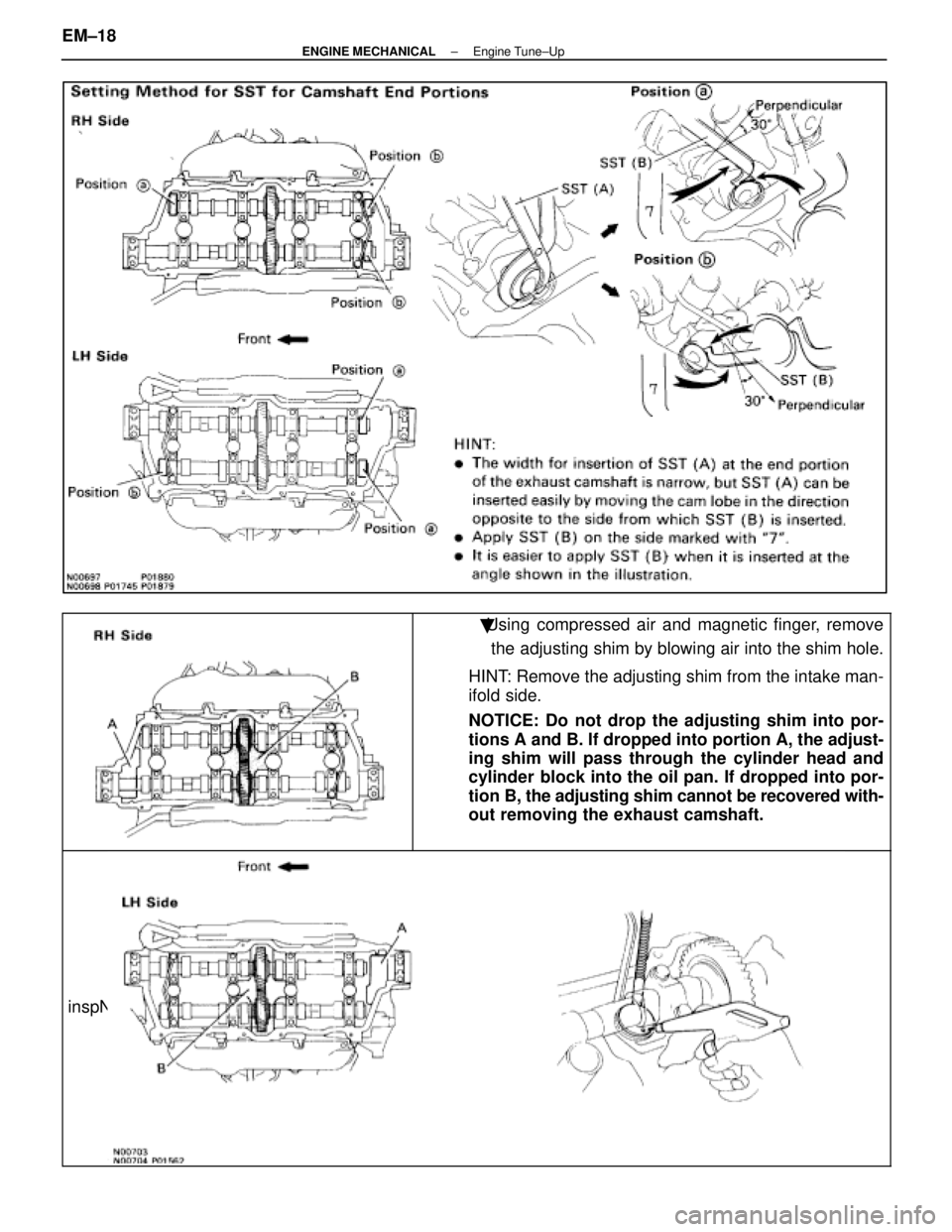
�Using compressed air and magnetic finger, removethe adjusting shim by blowing air into the shim hole.
HINT: Remove the adjusting shim from the intake man-
ifold side.
NOTICE: Do not drop the adjusting shim into por-
tions A and B. If dropped into portion A, the adjust-
ing shim will pass through the cylinder head and
cylinder block into the oil pan. If dropped into por-
tion B, the adjusting shim cannot be recovered with-
out removing the exhaust camshaft.
inspNFO
EM±18±
ENGINE MECHANICAL Engine Tune±Up
WhereEverybodyKnowsYourName
Page 1681 of 4087
 Install the theft deterrent horn with the bolt.
(b) Connect the connector.
24. REINSTALL RH CYLINDER HEAD COVER (a) Remove any oil packing (FIPG) material.")
23. REINSTALL THEFT DETERRENT HORN(a) Install the theft deterrent horn with the bolt.
(b) Connect the connector.
24. REINSTALL RH CYLINDER HEAD COVER (a) Remove any oil packing (FIPG) material.
(b) Apply seal packing to the cylinder head as shown in theillustration.
Seal packing: Part No. 08826±00080 or equivalent
(c) Install the gasket to the cylinder head cover.
(d) Install the seal washer to the mounting bolt.
(e) Install the cylinder head cover with the eight bolts.
Torque: 5.9 N Vm (60 kgf Vcm, 52 in. Vlbf)
(g) Connect the four high±tension cords to the spark plugs.
(h) Install the rear and front high±tension cord clamps with
the two bolts.
HINT: Place the front and rear ends of the front high±tension
cord clamp on the rear high±tension cord clamp and lower
high±tension cord cover.
(i) Fit the high±tension cords to the high±tension cord clamps. (See page IG±16)
25. REINSTALL LH CYLINDER HEAD COVER (a) Remove any oil packing (FIPG) material.
(b) Apply seal packing to the cylinder head as shown in theillustration.
Seal packing: Part No. 08826±00080 or equivalent
EM±22±
ENGINE MECHANICAL Engine Tune±Up
WhereEverybodyKnowsYourName
Page 1689 of 4087

COMPRESSION CHECK
HINT: If there is lack of power, excessive oil consumption or
poor fuel economy, measure the compression pressure.
1. WARM UP AND STOP ENGINE Allow the engine to warm up to normal operating tempera-
ture.
2. DISCONNECT DISTRIBUTOR CONNECTOR
3. DISCONNECT HIGH±TENSION CORDS FROM SPARK PLUGS (See steps 2 to 8 on pages EM±10 and 11)
4. DISCONNECT INJECTOR CONNECTORS
5. REMOVE SPARK PLUGS (See page IG±8)
6. CHECK CYLINDER COMPRESSION (a) Insert a compression tester into the spark plug hole.
(b) Fully open the throttle.
(c) While cranking the engine, measure the compressionpressure.
HINT: Always use a fully charged battery to obtain engine rev-
olution of 250 rpm or more.
(d) Repeat steps (a) through (c) for each cylinder.
NOTICE: This measurement must be done in as short
time as possible.
Compression:
1,226 kPa (12.5 kgf/cm
2, 178 psi) or more
Minimum pressure: 981 kPa (10.0 kgf/cm
2, 142 psi)
Difference between each cylinder:
98 kPa (1.0 kgf/cm
2, 14 psi) or less
(e) If the cylinder compression in one or more cylinders islow, pour a small amount of engine oil into the cylinder
through the spark plug hole and repeat steps (a) through
(c) for the cylinder with low compression.
w If adding oil helps the compression, the piston rings
and/or cylinder bore are probably worn or
damaged.
w If pressure stays low, a valve may be sticking or
seating improper, or there may be leakage past the
gasket.
7. REINSTALL SPARK PLUGS (See page IG±9)
Torque: 18 N Vm (180 kgf Vcm, 13 ft Vlbf)
8. RECONNECT INJECTOR CONNECTORS
9. RECONNECT HIGH±TENSION CORDS TO SPARK
PLUGS (See steps 14 to 20 on pages EM±17 to 19)
10. RECONNECT DISTRIBUTOR CONNECTOR
EM±22
±
ENGINE MECHANICAL Compression Check
WhereEverybodyKnowsYourName
Page 1691 of 4087
1. REMOVE WATER PUMP PULLEY AND RADIATOR (See steps 1 to 3, 6 and 7 on pages EM±64 and 66)
2. REMOVE NO. 3 AND NO. 2 TIMING BELT COVERS (a) R")
REMOVAL OF TIMING BELT
(See Components on page EM±23)1. REMOVE WATER PUMP PULLEY AND RADIATOR (See steps 1 to 3, 6 and 7 on pages EM±64 and 66)
2. REMOVE NO. 3 AND NO. 2 TIMING BELT COVERS (a) Remove the oil filler cap.
(b) Using a 5 mm hexagon wrench, remove the nine bolts,No. 3, No. 2 timing belt covers and gasket.
3. REMOVE DRIVE BELT TENSIONER Remove the three bolts and tensioner.
4. SET NO. 1 CYLINDER TO TDC/COMPRESSION (a) Turn the crankshaft pulley and align its groove withtiming mark º0º of the No. 1 timing belt cover.
NOTICE: Always turn the crankshaft clockwise.
(b) Check that the timing marks of the camshaft timing pulleys are aligned with the timing marks of the No. 4
timing belt cover.
If not, turn the crankshaft one revolution (360 5).
5. REMOVE TIMING BELT FROM CAMSHAFT TIMING PULLEYS
HINT: (Re±using timing belt)
Place matchmarks on the timing belt and camshaft timing
pulleys as shown in the illustration.
EM±24
±
ENGINE MECHANICAL Timing Belt
WhereEverybodyKnowsYourName
Page 1694 of 4087
INSPECTION OF TIMING BELT
COMPONENTS
1. INSPECT TIMING BELTNOTICE:w Do not bend, twist or turn the timing belt inside
out.
w Do not allow the timing belt to come into contact
with oil, water or steam.
w Do not make use of timing belt tension when
installing or removing the mount bolt of the
camshaft timing pulley.
If there are any defects as shown in the illustrations, check
the following points:
(a) Premature parting
w Check for proper installation.
w Check the timing cover gasket for damage and
proper installation.
(b) If the belt teeth are cracked or damaged, check to see if either the camshaft or water pump is locked.
(c) If there is noticeable wear or cracks on the belt face, check to see if there are nicks on the side of the idler
pulley lock.
(d) If there is wear or damage on only one side of the belt, check the belt guide and the alignment of each pulley.
±
ENGINE MECHANICAL Timing BeltEM±27
WhereEverybodyKnowsYourName
 Check the specific gravity of each cell.
Standard specific gravity:
1.27±1.29 when fully charged at 20 5C(68 5F)
I")