Page 9 of 4087

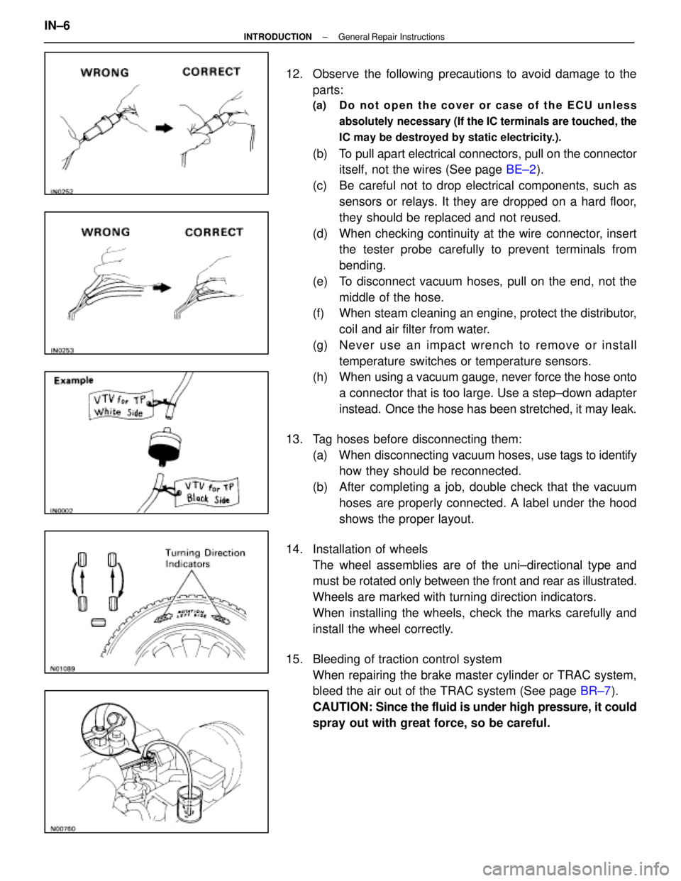
12. Observe the following precautions to avoid damage to theparts:
(a) Do not open the cover or case of the ECU unless
absolutely necessary (If the IC terminals are touched, the
IC may be destroyed by static electricity.).
(b) To pull apart electrical connectors, pull on the connectoritself, not the wires (See page BE±2).
(c) Be careful not to drop electrical components, such as sensors or relays. It they are dropped on a hard floor,
they should be replaced and not reused.
(d) When checking continuity at the wire connector, insert the tester probe carefully to prevent terminals from
bending.
(e) To disconnect vacuum hoses, pull on the end, not the middle of the hose.
(f) When steam cleaning an engine, protect the distributor,
coil and air filter from water.
(g) Ne ve r use an imp a ct wre n ch to re mo ve or in sta ll temperature switches or temperature sensors.
(h) When using a vacuum gauge, never force the hose onto
a connector that is too large. Use a step±down adapter
instead. Once the hose has been stretched, it may leak.
13. Tag hoses before disconnecting them: (a) When disconnecting vacuum hoses, use tags to identify
how they should be reconnected.
(b) After completing a job, double check that the vacuum hoses are properly connected. A label under the hood
shows the proper layout.
14. Installation of wheels The wheel assemblies are of the uni±directional type and
must be rotated only between the front and rear as illustrated.
Wheels are marked with turning direction indicators.
When installing the wheels, check the marks carefully and
install the wheel correctly.
15. Bleeding of traction control system When repairing the brake master cylinder or TRAC system,
bleed the air out of the TRAC system (See page BR±7).
CAUTION: Since the fluid is under high pressure, it could
spray out with great force, so be careful.
IN±6
±
INTRODUCTION General Repair Instructions
WhereEverybodyKnowsYourName
Page 170 of 4087
AMBIENT TEMPERATURE SENSOR
REMOVAL OF AMBIENT TEMPERATURE
SENSOR
1. REMOVE ENGINE UNDER COVER
2. REMOVE SENSOR
(a) Remove the clip and the sensor.
(b) Disconnect the connector.
INSPECTION OF AMBIENT
TEMPERATURE SENSOR
See page AC±46
INSTALLATION OF AMBIENT
TEMPERATURE SENSOR
1. INSTALL SENSOR
(a) Connect the connector.
(b) Install the sensor with the clip.
2. INSTALL ENGINE UNDER COVER
±
AIR CONDITIONING SYSTEM Ambient Temperature SensorAC±133
WhereEverybodyKnowsYourName
Page 506 of 4087
REMOVAL OF FRONT BUMPER
(See page BO±11)
1. REMOVE FENDER SPLASH SHIELD Remove fourteen screws, a bolt and the shield.
2. REMOVE NO. 2 ENGINE UNDER COVER Remove seven screws, five bolts and the cover.
3. REMOVE HEADLIGHT (Low Beam)
(a) Remove two nuts, a bolt and the headlight.
(b) Disconnect the connectors.
4. REMOVE UPPER BUMPER RETAINER (a) Remove the hood seal.
(b) Remove five screws and the retainer.
5. REMOVE BUMPER COVER ASSY (a) Remove six clips.
BO±12
±
BODY Bumper (Front Bumper)
WhereEverybodyKnowsYourName
Page 522 of 4087
2. REMOVE NO. 4 ENGINE UNDER COVER
3. REMOVE FRONT TRANSPORT HOOKRemove three bolts and the hook.
4. INSTALL FRONT TRANSPORT HOOK Install the hook with three bolts.
Torque: 64 N Vm (650 kgf Vcm, 47 ft Vlbf)
5. INSTALL NO. 4 ENGINE UNDER
6. INSTALL FENDER SPLASH SHIELD
Rear Transport Hook
REMOVAL AND INSTALLATION
(See page BO±27)
1. REMOVE SUPPORT Remove two bolts and the support.
2. REMOVE REAR TRANSPORT HOOK Remove two bolts and the hook.
3. INSTALL REAR TRANSPORT HOOK Install the hook with two bolts.
Torque: 64 N Vm (650 kgf Vcm, 47 ft Vlbf)
4. INSTALL SUPPORT
Install the support with two bolts.
BO±28
±
BODY Transport Hook (Front Transport Hook, Rear Transport Hook)
WhereEverybodyKnowsYourName
Page 523 of 4087
2. REMOVE NO. 4 ENGINE UNDER COVER
3. REMOVE FRONT TRANSPORT HOOKRemove three bolts and the hook.
4. INSTALL FRONT TRANSPORT HOOK Install the hook with three bolts.
Torque: 64 N Vm (650 kgf Vcm, 47 ft Vlbf)
5. INSTALL NO. 4 ENGINE UNDER
6. INSTALL FENDER SPLASH SHIELD
Rear Transport Hook
REMOVAL AND INSTALLATION
(See page BO±27)
1. REMOVE SUPPORT Remove two bolts and the support.
2. REMOVE REAR TRANSPORT HOOK Remove two bolts and the hook.
3. INSTALL REAR TRANSPORT HOOK Install the hook with two bolts.
Torque: 64 N Vm (650 kgf Vcm, 47 ft Vlbf)
4. INSTALL SUPPORT
Install the support with two bolts.
BO±28
±
BODY Transport Hook (Front Transport Hook, Rear Transport Hook)
WhereEverybodyKnowsYourName
Page 1138 of 4087

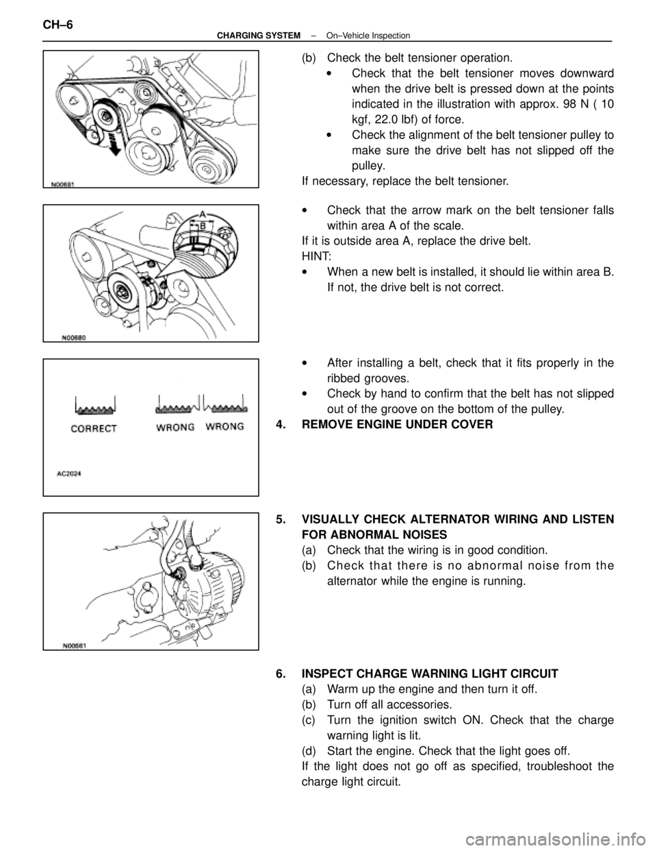
(b) Check the belt tensioner operation.w Check that the belt tensioner moves downward
when the drive belt is pressed down at the points
indicated in the illustration with approx. 98 N ( 10
kgf, 22.0 lbf) of force.
w Check the alignment of the belt tensioner pulley to
make sure the drive belt has not slipped off the
pulley.
If necessary, replace the belt tensioner.
w Check that the arrow mark on the belt tensioner falls
within area A of the scale.
If it is outside area A, replace the drive belt.
HINT:
w When a new belt is installed, it should lie within area B.
If not, the drive belt is not correct.
w After installing a belt, check that it fits properly in the
ribbed grooves.
w Check by hand to confirm that the belt has not slipped
out of the groove on the bottom of the pulley.
4. REMOVE ENGINE UNDER COVER
5. VISUALLY CHECK ALTERNATOR WIRING AND LISTEN FOR ABNORMAL NOISES
(a) Check that the wiring is in good condition.
(b) C h e c k t h a t t h e r e i s n o a bnormal noise from the
alternator while the engine is running.
6. INSPECT CHARGE WARNING LIGHT CIRCUIT (a) Warm up the engine and then turn it off.
(b) Turn off all accessories.
(c) Turn the ignition switch ON. Check that the charge
warning light is lit.
(d) Start the engine. Check that the light goes off.
If the light does not go off as specified, troubleshoot the
charge light circuit.
CH±6
±
CHARGING SYSTEM On±Vehicle Inspection
WhereEverybodyKnowsYourName
Page 1139 of 4087

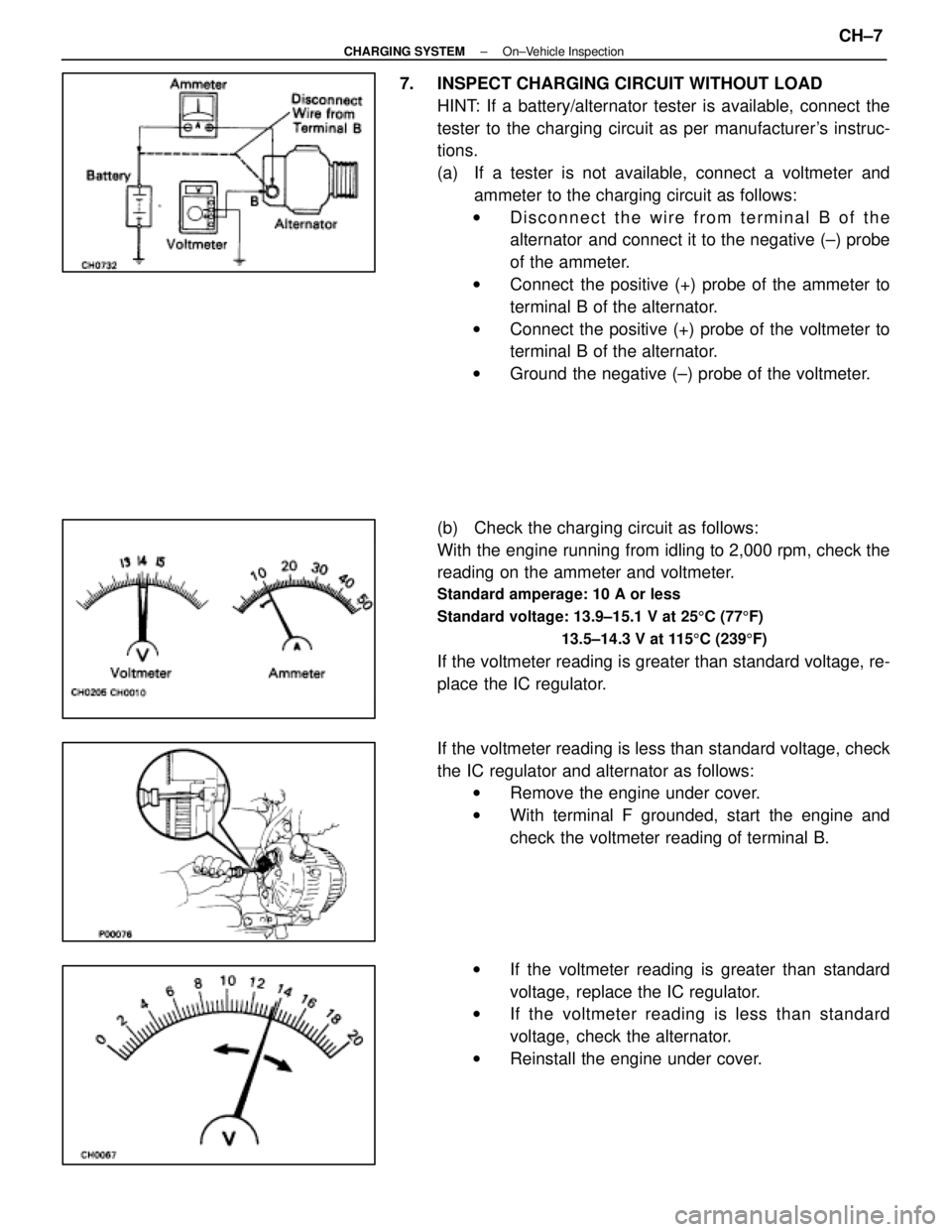
7. INSPECT CHARGING CIRCUIT WITHOUT LOADHINT: If a battery/alternator tester is available, connect the
tester to the charging circuit as per manufacturer's instruc-
tions.
(a) If a tester is not available, connect a voltmeter andammeter to the charging circuit as follows:
w Disconnect the wire from terminal B of the
alternator and connect it to the negative (±) probe
of the ammeter.
w Connect the positive (+) probe of the ammeter to
terminal B of the alternator.
w Connect the positive (+) probe of the voltmeter to
terminal B of the alternator.
w Ground the negative (±) probe of the voltmeter.
(b) Check the charging circuit as follows:
With the engine running from idling to 2,000 rpm, check the
reading on the ammeter and voltmeter.
Standard amperage: 10 A or less
Standard voltage: 13.9±15.1 V at 25 5C (77 5F)
13.5±14.3 V at 115 5C (239 5F)
If the voltmeter reading is greater than standard voltage, re-
place the IC regulator.
If the voltmeter reading is less than standard voltage, check
the IC regulator and alternator as follows:
w Remove the engine under cover.
w With terminal F grounded, start the engine and
check the voltmeter reading of terminal B.
w If the voltmeter reading is greater than standard
voltage, replace the IC regulator.
w If the voltmeter reading is less than standard
voltage, check the alternator.
w Reinstall the engine under cover.
±
CHARGING SYSTEM On±Vehicle InspectionCH±7
WhereEverybodyKnowsYourName
Page 1140 of 4087
8. INSPECT CHARGING CIRCUIT WITH LOAD(a) With the engine running at 2,000 rpm, turn on the highbeam headlights and place the heater blower switch at
ºHIº.
(b) Check the reading on the ammeter.
Standard amperage: 30 A or more
If the ammeter reading is less than standard amperage, re-
pair the alternator. (See page CH±9)
HINT: With the battery fully charged, the indication will some-
times be less than standard amperage.
9. REINSTALL ENGINE UNDER COVER
CH±8
±
CHARGING SYSTEM On±Vehicle Inspection
WhereEverybodyKnowsYourName