Page 1141 of 4087
ALTERNATOR
COMPONENTS FOR REMOVAL AND
INSTALLATION
REMOVAL OF ALTERNATOR
1. DISCONNECT CABLE FROM NEGATIVE TERMINAL OFBATTERY
CAUTION: Work must be started after approx. 20 se-
conds or longer from the time the ignition switch is
turned to the ºLOCKº position and the negative (±) termi-
nal cable is disconnected from the battery.
2. REMOVE ENGINE UNDER COVER
3. REMOVE DRIVE BELT
Loosen the belt tension by turning the drive belt tensioner
counterclockwise, and remove the drive belt.
HINT: The pulley bolt for the belt tensioner has a left±hand
thread.
±
CHARGING SYSTEM AlternatorCH±9
WhereEverybodyKnowsYourName
Page 1152 of 4087
INSTALLATION OF ALTERNATOR
(See Components on page CH±9)
1. INSTALL ALTERNATOR (a) Install the alternator and A/T oil cooler bracket with the
bolt and nut.
Torque: 37 N Vm (380 kgf Vcm, 27 ft Vlbf)
(b) Connect the alternator connector.
(c) Connect the alternator wire with the nut and cap.
2. INSTALL DRIVE BELT Install the drive belt by turning the drive belt tensioner coun-
terclockwise.
HINT: The pulley bolt for the belt tensioner has a left±hand
thread.
3. CONNECT CABLE TO NEGATIVE TERMINAL OF BATTERY
4. PERFORM ON±VEHICLE INSPECTION (See steps 6 to 8 on pages CH±6 to 8)
5. INSTALL ENGINE UNDER COVER
CH±20
±
CHARGING SYSTEM Alternator
WhereEverybodyKnowsYourName
Page 1157 of 4087
Front Door Trim Upper Panel (ABS/PVC)
Battery Insulator (PE) Roof Side Inner Garnish (ABS/PVC)
Front Pillar Garnish (ABS/PVC)
Speed Control Actuator Cover (PP)
Radiator Reserver Tank (PP)
Radiator Cover Plate (PP) Cool Air Intake
Duct (PP)
Spare Wheel Cover (PP)
Washer Jar (PP)
Junction Block Cover (PP)
Front Fender Liner (PE)
Front Fender Splash Shield (PE)
Engine Under Cover (PE) Engine Under Cover (PE)
Engine Under Cover (PP/PE)
HINT:
wResin material differs with model.
/ Made up of 2 or more kinds of materials.
PLASTIC BODY PARTSPP-5
WhereEverybodyKnowsYourName
Page 1277 of 4087
REMOVAL OF RADIATOR
(See Components on page CO±15)
1. REMOVE BATTERY CAUTION: Work must be started after approx. 20 seconds or
longer from the time the ignition switch is turned to the
ºLOCKº position and the negative (±) terminal cable is dis-
connected from the battery.
2. REMOVE ENGINE UNDER COVERS
3. DRAIN ENGINE COOLANT (See page CO±6)
4. REMOVE RADIATOR RESERVOIR TANK (a) Disconnect the coolant level sensor connector.
(b) Disconnect the following hoses:(1) Reservoir hose from water inlet housing
(2) Reservoir hose from radiator
(c) Remove the two bolts and reservoir tank bracket.
(d) Disconnect the reservoir tank from the reservoir tank bracket, and remove the reservoir tank.
5. DISCONNECT HOSES Disconnect the following hoses:(1) Upper radiator hose from radiator
(2) Lower radiator hose from radiator
(3) Two oil cooler hoses (for A/T) from radiator. Plug hose end.
CO±16
±
COOLIING SYSTEM Radiator
WhereEverybodyKnowsYourName
Page 1282 of 4087
9. FILL ENGINE WITH COOLANT (See page CO±7)
10. FILL COOLING FAN RESERVOIR TANK WITH FLUID (See pages CO±23 and 24)
11. CHECK AUTOMATIC TRANSMISSION FLUID LEVEL
(See page MA±11)
NOTICE: Do not overfill.
12. START ENGINE AND CHECK FOR LEAKS
13. INSTALL ENGINE UNDER COVER
±
COOLIING SYSTEM RadiatorCO±21
WhereEverybodyKnowsYourName
Page 1283 of 4087

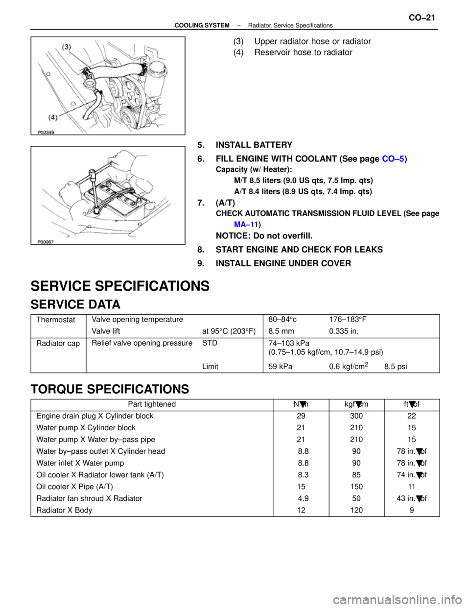
(3) Upper radiator hose or radiator
(4) Reservoir hose to radiator
5. INSTALL BATTERY
6. FILL ENGINE WITH COOLANT (See page CO±5)
Capacity (w/ Heater):
M/T 8.5 liters (9.0 US qts, 7.5 Imp. qts)
A/T 8.4 liters (8.9 US qts, 7.4 Imp. qts)
7. (A/T)
CHECK AUTOMATIC TRANSMISSION FLUID LEVEL (See pageMA±11 )
NOTICE: Do not overfill.
8. START ENGINE AND CHECK FOR LEAKS
9. INSTALL ENGINE UNDER COVER
SERVICE SPECIFICATIONS
SERVICE DATA
ThermostatValve opening temperature80±84 5c176±183 5F
Valve liftat 95 5C (203 5F) 8.5 mm0.335 in.
Radiator capRelief valve opening pressureSTD74±103 kPa
(0 75 1 05 k f/ 10 7 14 9 i)(0.75±1.05 kgf/cm, 10.7±14.9 psi)
Limit59 kPa0.6 kgf/cm28.5 psi
TORQUE SPECIFICATIONS
Part tightenedN �mkgf �cmft �lbf
Engine drain plug X Cylinder block2930022
Water pump X Cylinder block2121015
Water pump X Water by±pass pipe2121015
Water by±pass outlet X Cylinder head 8.89078 in. �lbf
Water inlet X Water pump 8.89078 in. �lbf
Oil cooler X Radiator lower tank (A/T) 8.38574 in. �lbf
Oil cooler X Pipe (A/T)1515011
Radiator fan shroud X Radiator 4.95043 in. �lbf
Radiator X Body121209
±
COOLING SYSTEM Radiator, Service SpecificationsCO±21
WhereEverybodyKnowsYourName
Page 1289 of 4087

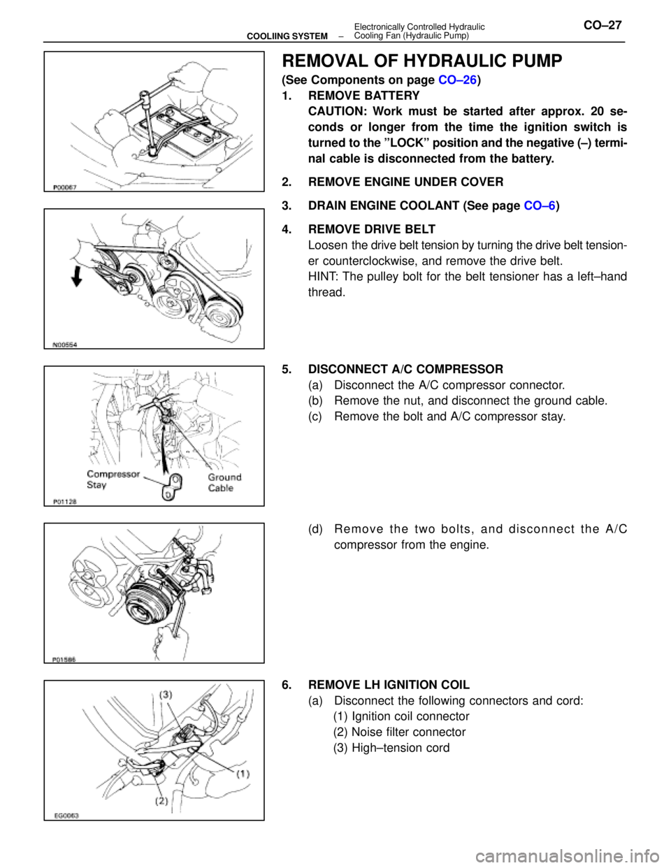
REMOVAL OF HYDRAULIC PUMP
(See Components on page CO±26)
1. REMOVE BATTERY CAUTION: Work must be started after approx. 20 se-
conds or longer from the time the ignition switch is
turned to the ºLOCKº position and the negative (±) termi-
nal cable is disconnected from the battery.
2. REMOVE ENGINE UNDER COVER
3. DRAIN ENGINE COOLANT (See page CO±6)
4. REMOVE DRIVE BELT Loosen the drive belt tension by turning the drive belt tension-
er counterclockwise, and remove the drive belt.
HINT: The pulley bolt for the belt tensioner has a left±hand
thread.
5. DISCONNECT A/C COMPRESSOR (a) Disconnect the A/C compressor connector.
(b) Remove the nut, and disconnect the ground cable.
(c) Remove the bolt and A/C compressor stay.
(d) R e m o v e t h e t w o b o l t s , a n d d i s c onnect the A/C
compressor from the engine.
6. REMOVE LH IGNITION COIL (a) Disconnect the following connectors and cord:(1) Ignition coil connector
(2) Noise filter connector
(3) High±tension cord
±
COOLIING SYSTEM Electronically Controlled Hydraulic
Cooling Fan (Hydraulic Pump)CO±27
WhereEverybodyKnowsYourName
Page 1308 of 4087
18. INSTALL BATTERY
19. FILL ENGINE WITH COOLANT (See page CO±7)
20. FILL COOLING FAN RESERVOIR TANK WITH FLUID (See pages CO±23 and 24)
21. START ENGINE AND CHECK FOR LEAKS
22. INSTALL ENGINE UNDER COVER
CO±46
±
COOLIING SYSTEM Electronically Controlled Hydraulic Cooling Fan
(Hydraulic Pump)
WhereEverybodyKnowsYourName