1991 FORD FESTIVA battery
[x] Cancel search: batteryPage 163 of 454

POWER STEERING PRESSURE SWITCH
1. Start engine and run it at idle. Remove connector from switch. Connect ohmmeter to switch terminals. Turn steering wheel from side to
side while observing ohmmeter.
2. Replace power steering switch if continuity does not exist with front wheels turned, or if continuity exists with wheels straight ahead.
THROTTLE POSITION SENSOR (1.6L)
Unplug connector from sensor. Connect ohmmeter to sensor terminals TP and SIGRTN (Orange and Blue/Yellow wires on mating connector).
Measure resistance at each throttle opening specified in THROTTLE POSITION SENSOR RESISTANCE
. Replace sensor if resistance is
not within specification.
THROTTLE POSITION SENSOR RESISTANCE
THROTTLE POSITION SWITCH (1.3L)
1. Ensure idle speed and ignition timing are adjusted to specification. Stop engine. Disconnect negative battery cable.
2. Unplug TPS connector at throttle body. Insert appropriate feeler gauge between throttle stop screw and stop lever. Check for continuity
between specified terminals on TPS connector. See ON-VEHICLE ADJUSTMENTS article and TPS CONTINUITY table.
TPS CONTINUITY
VANE AIRFLOW (VAF) METER
1. Check all wiring, harnesses, connectors and components for evidence of damage, overheating, shorting or looseness. If any defect exists,
repair as necessary.
2. Inspect vane airflow meter for damage and ensure measuring plate moves smoothly. Install BOB. Turn ignition on. Measure voltage
between BOB test pins VAF and ground on 1.3L, or between VAF and SIGRTN on 1.6L. Voltage measurements must be as specified in
VANE AIRFLOW METER VOLTAG
.
VANE AIRFLOW METER VOLTAGE
VANE AIR TEMPERATURE (VAT) SENSOR
1. Unplug connector from VAF meter. On 1.3L, connect ohmmeter to terminals VAT and ground (Green/Black and Black wires on mating
connector). On 1.6L, connect ohmmeter to VAF meter terminals VAT and SIGRTN (Brown and Blue/Yellow wires on mating
connector).
2. Measure intake air temperature. Measure resistance between specified terminals. See VANE AIR TEMPERATURE RESISTANCE
.
Replace VAF if resistance is not as specified.
Throttle Opening(1) Ohms
1/8989
1/41104
3/81278
1/21462
5/81480
3/41459
7/81144
Fully Open1072
(1)Resistance may vary by plus or minus 15 percent.
CAUT ION: DO NOT tam per with throttle stop screw at throttle lever. Doing so m ay result in dam age to the
throttle body.
Test Condition (1) Cont. Between IDL-TLCont. Between PSW-TL
.02" (.5 mm)YesNo
.03" (.7 mm)NoNo
Wide Open ThrottleNoYes
(1)Insert specified feeler gauge between throttle adjustment screw and stop lever.
Door Opening(1) Volts: 1.3L(1) Volts: 1.6L
Fully Closed.5-1.5(2) *
1/8.593.24
1/41.195.60
3/81.785.62
1/22.385.83
5/82.976.02
3/43.566.57
7/84.167.48
Fully Open4.5-5.07.87
(1)Voltage may vary by plus or minus 15 percent.
(2)Voltage not specified.
Page 3 of 7 MITCHELL 1 ARTICLE - I - SYSTEM/COMPONENT TESTS 1991 ENGINE PERFORMANCE Ford Motor Co. - Ford/Merc
...
3/10/2009 http://www.eautorepair.net/app/PrintItems.asp?S0=2097152&S1=0&SG=%7B7DD6473C%2DB5BB%2D4F20%2D9D70%2D
...
Page 166 of 454
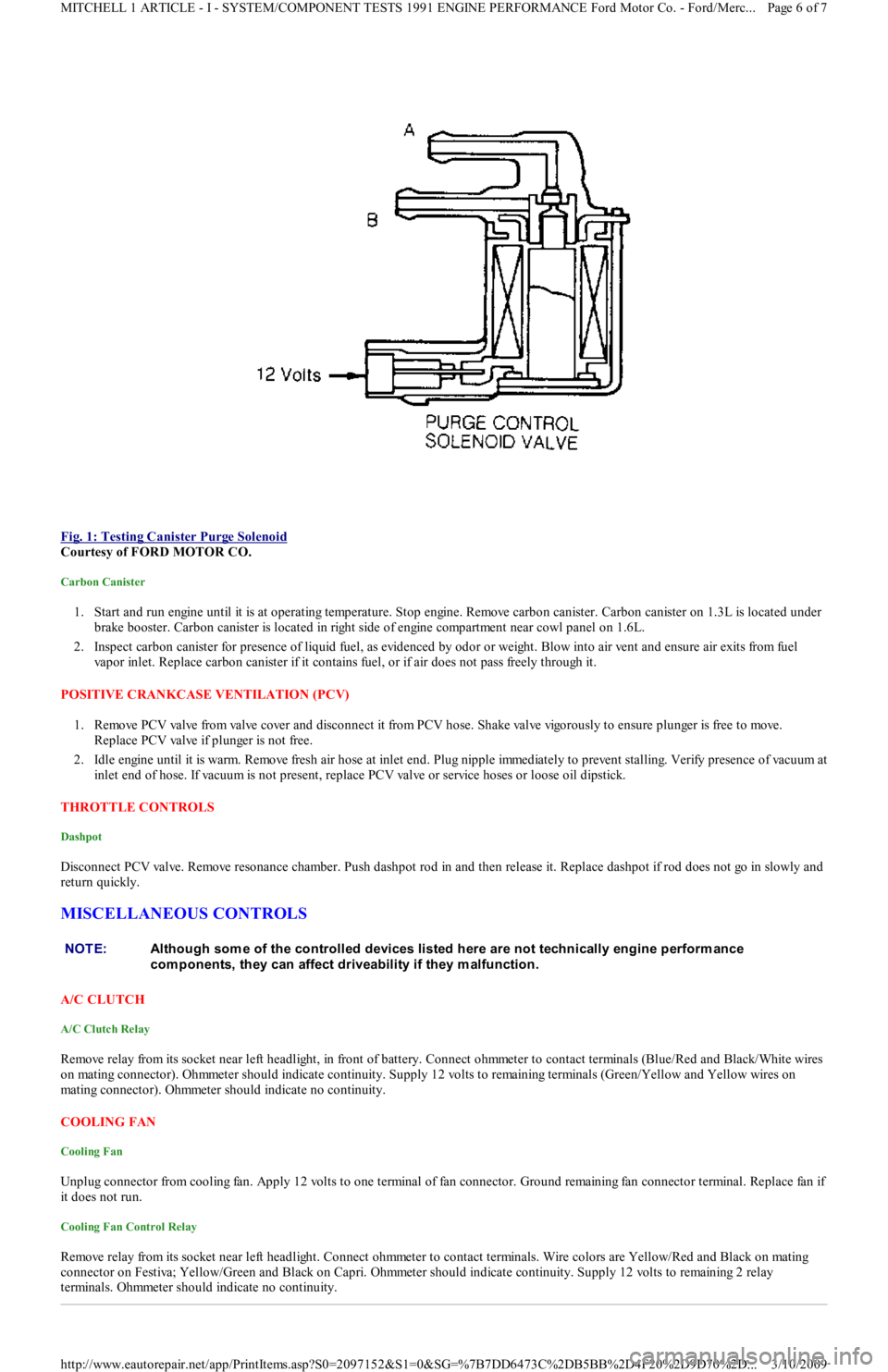
Fig. 1: Testing Canister Purge Solenoid
Courtesy of FORD MOTOR CO.
Carbon Canister
1. Start and run engine until it is at operating temperature. Stop engine. Remove carbon canister. Carbon canister on 1.3L is located under
brake booster. Carbon canister is located in right side of engine compartment near cowl panel on 1.6L.
2. Inspect carbon canister for presence of liquid fuel, as evidenced by odor or weight. Blow into air vent and ensure air exits fro m fu el
vapor inlet. Replace carbon canister if it contains fuel, or if air does not pass freely through it.
POSITIVE CRANKCASE VENTILATION (PCV)
1. Remove PCV valve from valve cover and disconnect it from PCV h o se . S h a ke va l ve vigo r o u sl y t o e n su r e p l u n ge r is fr e e t o mo ve .
Replace PCV valve if plunger is not free.
2. Idle engine until it is warm. Remove fresh air hose at inlet end. Plug nipple immediately to prevent stalling. Verify presence of vacuum at
inlet end of hose. If vacuum is not present, replace PCV valve or service hoses or loose oil dipstick.
THROTTLE CONTROLS
Dashpot
Disconnect PCV valve. Remove resonance chamber. Push dashpot rod in and then release it. Replace dashpot if rod does not go in slowly and
return quickly.
MISCELLANEOUS CONTROLS
A/C CLUTCH
A/C Clutch Relay
Remove relay from its socket near left headlight, in front of battery. Connect ohmmeter to contact terminals (Blue/Red and Black/White wires
on mating connector). Ohmmeter should indicate continuity. Supply 12 volts to remaining terminals (Green/Yellow and Yellow wires on
mating connector). Ohmmeter should indicate no continuity.
COOLING FAN
Cooling Fan
Unplug connector from cooling fan. Apply 12 volts to one terminal of fan connector. Ground remaining fan connector terminal. Replace fan if
it does not run.
Cooling Fan Control Relay
Remove relay from its socket near left headlight. Connect ohmmeter to contact terminals. Wire colors are Yellow/Red and Black on mating
connector on Festiva; Yellow/Green and Black on Capri. Ohmmeter should indicate continuity. Supply 12 volts to remaining 2 relay
terminals. Ohmmeter should indicate no continuity.
NOTE:Although som e of the controlled devices listed here are not technically engine perform ance
com ponents, they can affect driveability if they m alfunction.
Page 6 of 7 MITCHELL 1 ARTICLE - I - SYSTEM/COMPONENT TESTS 1991 ENGINE PERFORMANCE Ford Motor Co. - Ford/Merc
...
3/10/2009 http://www.eautorepair.net/app/PrintItems.asp?S0=2097152&S1=0&SG=%7B7DD6473C%2DB5BB%2D4F20%2D9D70%2D
...
Page 170 of 454
Engine control system communicates malfunctions to technician through service codes. These service codes are 2-digit numbers representing a
particular defect. Service codes are transmitted through STO connector.
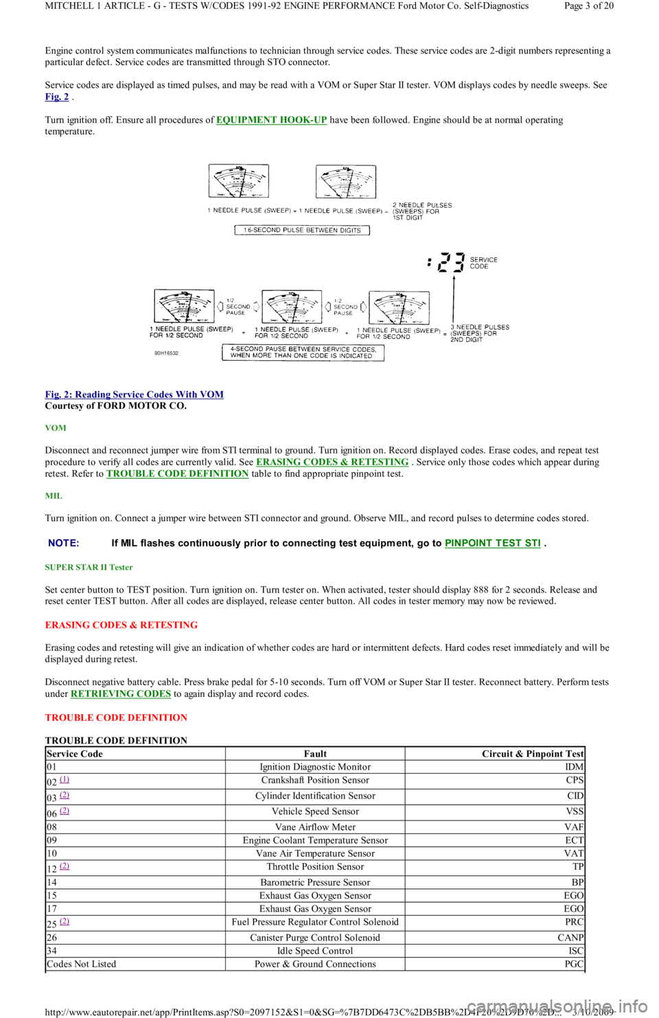
Service codes are displayed as timed pulses, and may be read with a VOM or Super Star II tester. VOM displays codes by needle sweeps. See
Fig. 2
.
Turn ignition off. Ensure all procedures of EQUIPMENT HOOK
-UP have been followed. Engine should be at normal operating
temperature.
Fig. 2: Reading Service Codes With VOM
Courtesy of FORD MOTOR CO.
VOM
Disconnect and reconnect jumper wire from STI terminal to ground. Turn ignition on. Record displayed codes. Erase codes, and repeat test
procedure to verify all codes are currently valid. See ERASING CODES & RETESTING . Service only those codes which appear during
retest. Refer to TROUBLE CODE DEFINITION
table to find appropriate pinpoint test.
MIL
Turn ignition on. Connect a jumper wire between STI connector and ground. Observe MIL, and record pulses to determine codes stored.
SUPER STAR II Tester
Set center button to TEST position. Turn ignition on. Turn tester on. When activated, tester should display 888 for 2 seconds. Release and
reset center TEST button. After all codes are displayed, release center button. All codes in tester memory may now be reviewed.
ERASING CODES & RETESTING
Erasing codes and retesting will give an indication of whether codes are hard or intermittent defects. Hard codes reset immediately and will be
displayed during retest.
Disconnect negative battery cable. Press brake pedal for 5-10 seconds. Turn off VOM or Super Star II tester. Reconnect battery. Perform tests
under RETRIEVING CODES
to again display and record codes.
TROUBLE CODE DEFINITION
TROUBLE CODE DEFINITION
NOTE:If MIL flashes continuously prior to connecting test equipm ent, go to PINPOINT T EST ST I .
Service CodeFaultCircuit & Pinpoint Test
01Ignition Diagnostic MonitorIDM
02 (1) Crankshaft Position SensorCPS
03 (2) Cylinder Identification SensorCID
06 (2) Vehicle Speed SensorVSS
08Vane Airflow MeterVAF
09Engine Coolant Temperature SensorECT
10Vane Air Temperature SensorVAT
12 (2) Throttle Position SensorTP
14Barometric Pressure SensorBP
15Exhaust Gas Oxygen SensorEGO
17Exhaust Gas Oxygen SensorEGO
25 (2) Fuel Pressure Regulator Control SolenoidPRC
26Canister Purge Control SolenoidCANP
34Idle Speed ControlISC
Codes Not ListedPower & Ground ConnectionsPGC
Page 3 of 20 MITCHELL 1 ARTICLE - G - TESTS W/CODES 1991-92 ENGINE PERFORMANCE Ford Motor Co. Self-Diagnostics
3/10/2009 http://www.eautorepair.net/app/PrintItems.asp?S0=2097152&S1=0&SG=%7B7DD6473C%2DB5BB%2D4F20%2D9D70%2D
...
Page 171 of 454
CLEARING CODES
Clearing Codes Procedure
Disconnect negative battery cable. Press brake pedal for 5-10 seconds. Turn off VOM or Super Star II tester. Reconnect battery.
ECA LOCATION
ECA is located on center console behind kick panel on Capri, and under instrument panel on driver side of Festiva.
QUICK TESTS
KEY ON, ENGINE OFF (KOEO) SELF-TEST
KOEO
1. This is a test of electronic engine control system, conducted with power (voltage) applied and engine not running. Activate self-test, and
record all codes displayed.
2. Erase codes, and repeat self-test. Diagnose only codes occurring during repeat self-test. See TROUBLE CODE DEFINITION
table. If
no codes are present, proceed to KEY ON, ENGINE RUNNING (KOER) SELF
-TEST .
KEY ON, ENGINE RUNNING (KOER) SELF-TEST
KOER
1. Deactivate self-test. Start and run engine at 2000 RPM for 2 minutes to warm up EGO sensor. Turn off engine and wait 10 seconds.
2. Restart engine, and activate self-test. Record all service codes displayed. See TROUBLE CODE DEFINITION
table. If no codes are
present, proceed to SWITCH MONITOR TEST
.
SWITCH MONITOR TEST
This test procedure checks input signals received by ECA from individual switches. Use following procedure to perform switch monitor test:
Turn engine off and allow it to cool.
Ensure all accessories are turned off.
Deactivate self-test.
Ensure transmission is in Neutral or Park.
Turn ignition on.
SUPER STAR II Tester
Connect Super Star II tester adapter cable. Turn on tester. Latch center button. Operate each switch listed in SWITCH MONITOR TEST
table. Note output of LED on adapter cable as each switch operates. Record test results.
VOM
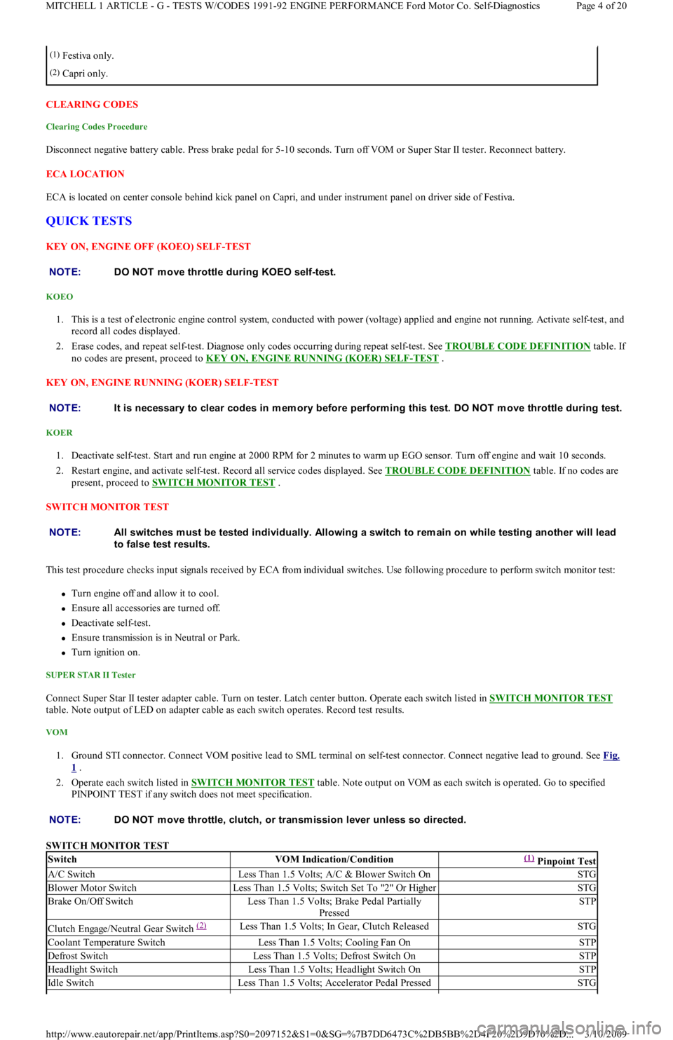
1. Ground STI connector. Connect VOM positive lead to SML terminal on self-test connector. Connect negative lead to ground. See Fig.
1 .
2. Operate each switch listed in SWITCH MONITOR TEST
table. Note output on VOM as each switch is operated. Go to specified
PINPOINT TEST if any switch does not meet specification.
SWITCH MONITOR TEST
(1)Festiva only.
(2)Capri only.
NOTE:DO NOT m ove throttle during KOEO self-test.
NOTE:It is necessary to clear codes in m em ory before perform ing this test. DO NOT m ove throttle during test.
NOTE:All switches m ust be tested individually. Allowing a switch to rem ain on while testing another will lead
to false test results.
NOTE:DO NOT m ove throttle, clutch, or transm ission lever unless so directed.
SwitchVOM Indication/Condition(1) Pinpoint Test
A/C SwitchLess Than 1.5 Volts; A/C & Blower Switch OnSTG
Blower Motor SwitchLess Than 1.5 Volts; Switch Set To "2" Or HigherSTG
Brake On/Off SwitchLess Than 1.5 Volts; Brake Pedal Partially
PressedSTP
Clutch Engage/Neutral Gear Switch (2) Less Than 1.5 Volts; In Gear, Clutch ReleasedSTG
Coolant Temperature SwitchLess Than 1.5 Volts; Cooling Fan OnSTP
Defrost SwitchLess Than 1.5 Volts; Defrost Switch OnSTP
Headlight SwitchLess Than 1.5 Volts; Headlight Switch OnSTP
Id l e Swit chLess Than 1.5 Volts; Accelerator Pedal PressedSTG
Page 4 of 20 MITCHELL 1 ARTICLE - G - TESTS W/CODES 1991-92 ENGINE PERFORMANCE Ford Motor Co. Self-Diagnostics
3/10/2009 http://www.eautorepair.net/app/PrintItems.asp?S0=2097152&S1=0&SG=%7B7DD6473C%2DB5BB%2D4F20%2D9D70%2D
...
Page 183 of 454
1. Turn ignition off. Install BOB. Leave ECA disconnected. Connect test light between STI test pin on BOB and 12-volt source. If test
light comes on, go to PINPOINT TEST STO
. If light does not come on, go to next step.
2. Leave test light connected. Ground STI connector. If test light does not come on, repair open circuit between STI connector and ECA.
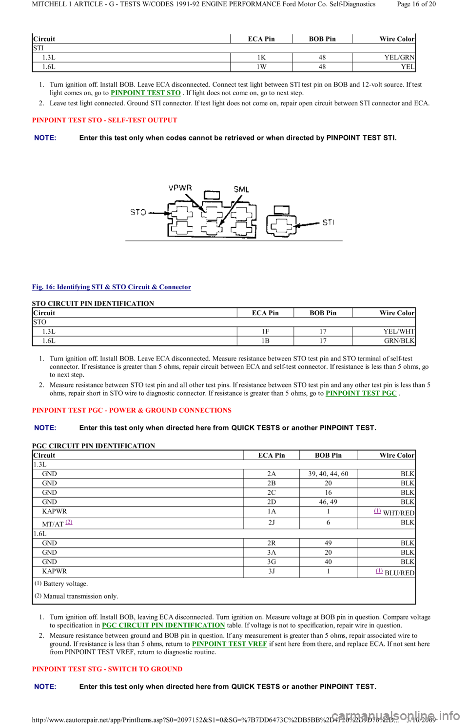
PINPOINT TEST STO - SELF-TEST OUTPUT
Fig. 16: Identifying STI & STO Circuit & Connector
STO CIRCUIT PIN IDENTIFICATION
1. Turn ignition off. Install BOB. Leave ECA disconnected. Measure resistance between STO test pin and STO terminal of self-test
connector. If resistance is greater than 5 ohms, repair circuit between ECA and self-test connector. If resistance is less than 5 ohms, go
to next step.
2. Measure resistance between STO test pin and all other test pins. If resistance between STO test pin and any other test pin is less than 5
ohms, repair short in STO wire to diagnostic connector. If resistance is greater than 5 ohms, go to PINPOINT TEST PGC
.
PINPOINT TEST PGC - POWER & GROUND CONNECTIONS
PGC CIRCUIT PIN IDENTIFICATION
1. Turn ignition off. Install BOB, leaving ECA disconnected. Turn ignition on. Measure voltage at BOB pin in question. Compare voltage
to specification in PGC CIRCUIT PIN IDENTIFICATION
table. If voltage is not to specification, repair wire in question.
2. Measure resistance between ground and BOB pin in question. If any measurement is greater than 5 ohms, repair associated wire to
ground. If resistance is less than 5 ohms, return to PINPOINT TEST VREF
if sent here from there, and replace ECA. If not sent here
from PINPOINT TEST VREF, return to diagnostic routine.
PINPOINT TEST STG - SWITCH TO GROUND
CircuitECA PinBOB PinWire Color
STI
1.3L1K48YEL/GRN
1.6L1W48YEL
NOTE:Enter this test only when codes cannot be retrieved or when directed by PINPOINT T EST ST I.
CircuitECA PinBOB PinWire Color
STO
1.3L1F17YEL/WHT
1.6L1B17GRN/BLK
NOTE:Enter this test only when directed here from QUICK T EST S or another PINPOINT T EST .
CircuitECA PinBOB PinWire Color
1.3L
GND2A39, 40, 44, 60BLK
GND2B20BLK
GND2C16BLK
GND2D46, 49BLK
KAPWR1A1(1) WHT/RED
MT/AT (2) 2J6BLK
1.6L
GND2R49BLK
GND3A20BLK
GND3G40BLK
KAPWR3J1(1) BLU/RED
(1)Battery voltage.
(2)Manual transmission only.
NOTE:Enter this test only when directed here from QUICK T EST S or another PINPOINT T EST .
Page 16 of 20 MITCHELL 1 ARTICLE - G - TESTS W/CODES 1991-92 ENGINE PERFORMANCE Ford Motor Co. Self-Diagnostics
3/10/2009 http://www.eautorepair.net/app/PrintItems.asp?S0=2097152&S1=0&SG=%7B7DD6473C%2DB5BB%2D4F20%2D9D70%2D
...
Page 184 of 454
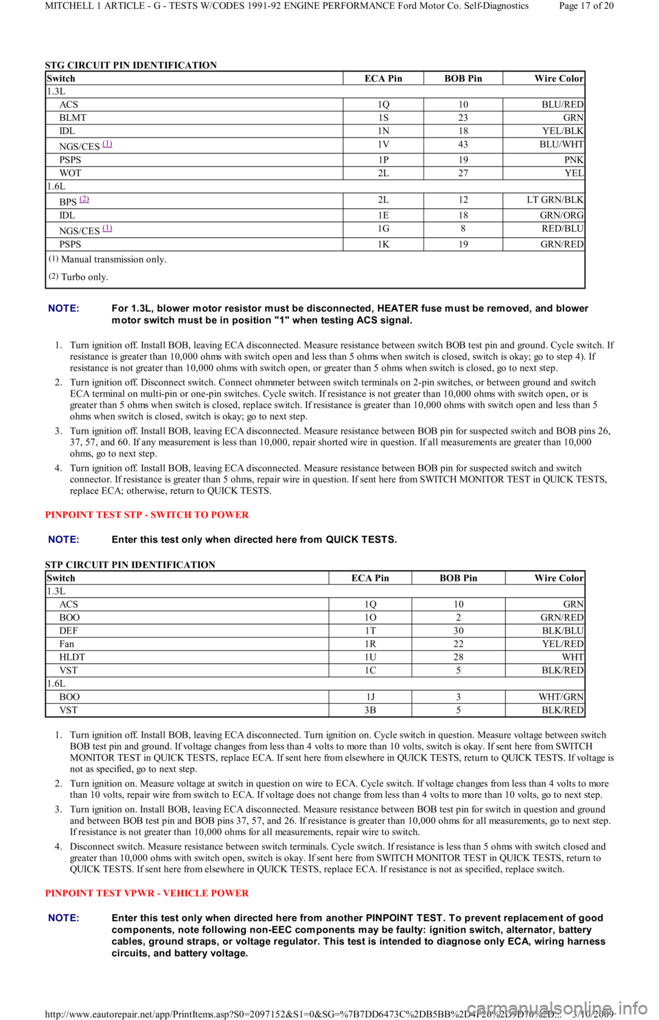
STG CIRCUIT PIN IDENTIFICATION
1. Turn ignition off. Install BOB, leaving ECA disconnected. Measure resistance between switch BOB test pin and ground. Cycle switch. I
f
resistance is greater than 10,000 ohms with switch open and less than 5 ohms when switch is closed, switch is okay; go to step 4). If
resistance is not greater than 10,000 ohms with switch open, or greater than 5 ohms when switch is closed, go to next step.
2. Turn ignition off. Disconnect switch. Connect ohmmeter between switch terminals on 2-pin switches, or between ground and switch
ECA terminal on multi-pin or one-pin switches. Cycle switch. If resistance is not greater than 10,000 ohms with switch open, or is
greater than 5 ohms when switch is closed, replace switch. If resistance is greater than 10,000 ohms with switch open and less than 5
ohms when switch is closed, switch is okay; go to next step.
3. Turn ignition off. Install BOB, leaving ECA disconnected. Measure resistance between BOB pin for suspected switch and BOB pins 26,
37, 57, and 60. If any measurement is less than 10,000, repair shorted wire in question. If all measurements are greater than 10,000
ohms, go to next step.
4. Turn ignition off. Install BOB, leaving ECA disconnected. Measure resistance between BOB pin for suspected switch and switch
connector. If resistance is greater than 5 ohms, repair wire in question. If sent here from SWITCH MONITOR TEST in QUICK TESTS,
replace ECA; otherwise, return to QUICK TESTS.
PINPOINT TEST STP - SWITCH TO POWER
STP CIRCUIT PIN IDENTIFICATION
1. Turn ignition off. Install BOB, leaving ECA disconnected. Turn ignition on. Cycle switch in question. Measure voltage between switch
BOB test pin and ground. If voltage changes from less than 4 volts to more than 10 volts, switch is okay. If sent here from SWITCH
MONITOR TEST in QUICK TESTS, replace ECA. If sent here from elsewhere in QUICK TESTS, return to QUICK TESTS. If voltage is
not as specified, go to next step.
2. Turn ignition on. Measure voltage at switch in question on wire to ECA. Cycle switch. If voltage changes from less than 4 volts to more
than 10 volts, repair wire from switch to ECA. If voltage does not change from less than 4 volts to more than 10 volts, go to next step.
3. Turn ignition on. Install BOB, leaving ECA disconnected. Measure resistance between BOB test pin for switch in question and ground
and between BOB test pin and BOB pins 37, 57, and 26. If resistance is greater than 10,000 ohms for all measurements, go to next step.
If resistance is not greater than 10,000 ohms for all measurements, repair wire to switch.
4. Disconnect switch. Measure resistance between switch terminals. Cycle switch. If resistance is less than 5 ohms with switch closed and
greater than 10,000 ohms with switch open, switch is okay. If sent here from SWITCH MONITOR TEST in QUICK TESTS, return to
QUICK TESTS. If sent here from elsewhere in QUICK TESTS, replace ECA. If resistance is not as specified, replace switch.
PINPOINT TEST VPWR - VEHICLE POWER
SwitchECA PinBOB PinWire Color
1.3L
ACS1Q10BLU/RED
BLMT1S23GRN
IDL1N18YEL/BLK
NGS/CES (1) 1V43BLU/WHT
PSPS1P19PNK
WOT2L27YEL
1.6L
BPS (2) 2L12LT GRN/BLK
IDL1E18GRN/ORG
NGS/CES (1) 1G8RED/BLU
PSPS1K19GRN/RED
(1)Manual transmission only.
(2)Turbo only.
NOTE:For 1.3L, blower m otor resistor m ust be disconnected, HEAT ER fuse m ust be rem oved, and blower
m otor switch m ust be in position "1" when testing ACS signal.
NOTE:Enter this test only when directed here from QUICK T EST S.
SwitchECA PinBOB PinWire Color
1.3L
ACS1Q10GRN
BOO1O2GRN/RED
DEF1T30BLK/BLU
Fan1R22YEL/RED
HLDT1U28WHT
VST1C5BLK/RED
1.6L
BOO1J3WHT/GRN
VST3B5BLK/RED
NOTE:Enter this test only when directed here from another PINPOINT T EST . T o prevent replacem ent of good
com ponents, note following non-EEC com ponents m ay be faulty: ignition switch, alternator, battery
cables, ground straps, or voltage regulator. T his test is intended to diagnose only ECA, wiring harness
circuits, and battery voltage.
Page 17 of 20 MITCHELL 1 ARTICLE - G - TESTS W/CODES 1991-92 ENGINE PERFORMANCE Ford Motor Co. Self-Diagnostics
3/10/2009 http://www.eautorepair.net/app/PrintItems.asp?S0=2097152&S1=0&SG=%7B7DD6473C%2DB5BB%2D4F20%2D9D70%2D
...
Page 185 of 454
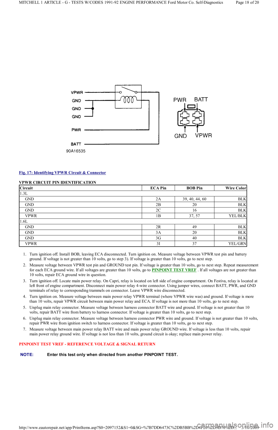
Fig. 17: Identifying VPWR Circuit & Connector
VPWR CIRCUIT PIN IDENTIFICATION
1. Turn ignition off. Install BOB, leaving ECA disconnected. Turn ignition on. Measure voltage between VPWR test pin and battery
gr o u n d . If vo l t a ge is n o t gr e a t e r t h a n 1 0 vo l t s, go t o st e p 3). If voltage is greater than 10 volts, go to next step.
2. Measure voltage between VPWR test pin and GROUND test pin. If voltage is greater than 10 volts, go to next step. Repeat measurement
for each ECA ground wire. If all voltages are greater than 10 volts, go to PINPOINT TEST VREF
. If all voltages are not greater than
10 volts, repair ECA ground wire in question.
3. Turn ignition off. Locate main power relay. On Capri, relay is located on left side of engine compartment. On Festiva, relay is located at
left front of engine compartment. Disconnect main power relay 4-wire connector. Using jumper wires, connect BATT, PWR, and GND
terminals of relay to corresponding trammels on connector. Leave VPWR wire disconnected.
4. Turn ignition on. Measure voltage between main power relay VPWR terminal (where VPWR wire was) and ground. If voltage is more
than 10 volts, repair VPWR circuit between main power relay and ECA. If voltage is not more than 10 volts, go to next step.
5. Unplug main relay connector. Measure voltage between harness connector BATT wire and ground. If voltage is not greater than 10
volts, repair BATT wire from battery to harness connector. If voltage is greater than 10 volts, go to next step.
6. Unplug main relay connector. Measure voltage between harness connector PWR wire and ground. If voltage is not greater than 10 volts,
repair PWR wire from ignition switch to harness connector. If voltage is greater than 10 volts, go to next step.
7. Measure voltage between main power relay BATT wire and main power relay GROUND wire. If voltage is less than 10 volts, repair
main power relay ground wire. If voltage is not less than 10 volts, ground circuit is okay; replace main power relay.
PINPOINT TEST VREF - REFERENCE VOLTAGE & SIGNAL RETURN
CircuitECA PinBOB PinWire Color
1.3L
GND2A39, 40, 44, 60BLK
GND2B20BLK
GND2C16BLK
VPWR1B37, 57YEL/BLK
1.6L
GND2R49BLK
GND3A20BLK
GND3G40BLK
VPWR3I37YEL/GRN
NOTE:Enter this test only when directed from another PINPOINT T EST .
Page 18 of 20 MITCHELL 1 ARTICLE - G - TESTS W/CODES 1991-92 ENGINE PERFORMANCE Ford Motor Co. Self-Diagnostics
3/10/2009 http://www.eautorepair.net/app/PrintItems.asp?S0=2097152&S1=0&SG=%7B7DD6473C%2DB5BB%2D4F20%2D9D70%2D
...
Page 190 of 454

POOR FUEL ECONOMY
Verify intake air is not restricted.
Verify fuel pressure is within specification.
Check ignition module.
Check canister purge solenoid.
Check vane air temperature sensor.
Check vane airflow meter.
Check heated exhaust gas oxygen sensor.
EXHAUST SMOKE/ODOR
Check vane air temperature sensor.
Check vane airflow meter.
Check exhaust gas oxygen sensor.
FUEL ODOR/LEAKS
Check evaporative emission control components.
Check rollover vent valve.
Check by-pass air control valve.
FAILS EMISSION TEST
Check canister purge solenoid.
Check pressure regulator control solenoid.
Check heated exhaust gas oxygen sensor.
Check by-pass air control valve.
INTERMITTENTS
INTERMITTENT PROBLEM DIAGNOSIS
Intermittent fault testing requires duplicating circuit or component failure to identify problem. These procedures may lead to computer setting
a fault code (on some systems) which may help in diagnosis.
If problem vehicle does not produce fault codes, monitor voltage or resistance values using a DVOM while attempting to reproduce conditions
causing intermittent fault. A status change on DVOM indicates a fault has been located.
Use a DVOM to pinpoint faults. When monitoring voltage, ensure ignition switch is in ON position or engine is running. Ensure ign it io n
switch is in OFF position or negative battery cable is disconnected when monitoring circuit resistance. Status changes on DVOM during test
procedures indicate area of fault.
TEST PROCEDURES
INTERMITTENT SIMULATION
To reproduce conditions creating an intermittent fault, use following methods:
Lightly vibrate component.
Heat component.
Wiggle or bend wiring harness.
Spray component with water.
Remove/apply vacuum source.
Monitor circuit/component voltage or resistance while simulating intermittent. If engine is running, monitor for self-diagnostic codes. Use test
results to identify a faulty component or circuit.
Copyr ight 2009 Mitchell Repair Information Company, LLC. All Rights Reserved.
Article GUID: A00022699
Page 3 of 3 MITCHELL 1 ARTICLE - H - TESTS W/O CODES 1991-92 ENGINE PERFORMANCE Ford Motor Co. Trouble Shooting -
...
3/10/2009 http://www.eautorepair.net/app/PrintItems.asp?S0=2097152&S1=0&SG=%7B7DD6473C%2DB5BB%2D4F20%2D9D70%2D
...