1991 FORD FESTIVA battery
[x] Cancel search: batteryPage 46 of 454

Back To Article
ELECT RICAL COMPONENT LOCAT OR
1991-92 ELECT RICAL COMPONENT LOCAT ION Ford Motor Co. Electrical Com ponents
BUZZERS, RELAYS & TIMERS
BUZZERS, RELAYS & TIMERS LOCATION
CIRCUIT PROTECTION DEVICES
CIRCUIT PROTECTION DEVICES LOCATION
CONTROL UNITS
CONTROL UNITS LOCATION
SENDING UNITS & SENSORS
SENDING UNITS & SENSORS LOCATION
MOTORS
MOTORS LOCATION
ComponentLocation
A/C Clutch Relay (1991)On right front of engine bay, near power
steering pump.
A/C RelayOn left front corner of engine bay, left of
cooling fan. See Fig. 1
& Fig. 2
A/C Wide Open Throttle (WAC) RelayOn left front corner of engine bay, left of
cooling fan. See Fig. 1
& Fig. 2 .
Cooling Fan RelayOn left front fender panel, near
headlight. See Fig. 1
& Fig. 2 .
Condenser Fan RelayOn left front of engine bay, left of
cooling fan. See Fig. 1
& Fig. 2 .
Daytime Running Light (DRL) Relay (Canada) (1992)On left front corner of engine bay, near
headlight. See Fig. 1
.
Fuel Pump RelayBehind left side of dash, near ECA.
Headlight RelayBehind left headlight. See Fig. 1 .
Horn RelayUnder left side of dash. See Fig. 3 .
Main RelayIn left front corner of engine bay, near
battery.
P a r kin g Ligh t R e l a yOn right front corner of engine bay. See
Fig. 1
.
Turn Signal/Flasher RelayUnder left side of dash, behind ECA.
See Fig. 3
.
ComponentLocation
A/C In-Line FuseOn left side of heater case.
Condenser Fan In-Line FuseOn right side of steering column.
Fuse PanelBehind access panel, to left of steering column.
Fusible LinksOn left front strut tower. See Fig. 1 .
ComponentLocation
Electronic Control Assembly (ECA)Behind left side of dash, left of steering column.
Passive Restraint ModuleUnder driver's seat.
ComponentLocation
Airflow MeterOn right front corner of engine bay. See Fig. 1 .
Coolant Temperature Sending UnitBelow thermostat housing.
Crankshaft Position SensorInside distributor. See Fig. 1 .
EGR Temperature Sensor (1991)In exhaust manifold, near EGR valve.
Engine Coolant Temperature (ECT) SensorOn top of engine, near injector No. 1.
Fuel Gauge Sending Unit (1992)In fu el t an k.
Throttle Position Sensor (TPS)On left side of throttle body. See Fig. 1 .
ComponentLocation
Blower MotorUnder center of dash, behind
radio.
Windshield Washer Motors:
Front (1991)On right front fender panel,
bottom of washer reservoir.
Front (1992)On left front corner of engine
bay, in front of battery.
RearOn body panel, behind right
rear quarter panel.
Windshield Wiper Motor
Page 1 of 3 MITCHELL 1 ARTICLE - ELECTRICAL COMPONENT LOCATOR 1991-92 ELECTRICAL COMPONENT LOCATION For...
3/10/2009 http://www.eautorepair.net/app/PrintItems.asp?S0=2097152&S1=0&SG=%7B959286D2%2D3A85%2D4BFC%2D9C5C%2D
...
Page 50 of 454
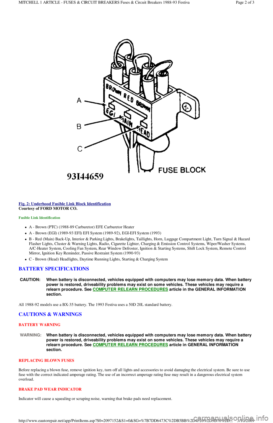
Fig. 2: Underhood Fusible Link Block Identification
Courtesy of FORD MOTOR CO.
Fusible Link Identification
A - Brown (PTC) (1988-89 Carburetor) EFE Carburetor Heater
A - Brown (EGI) (1989-93 EFI) EFI System (1989-92), EGI-EFI System (1993)
B - Red (Main) Back-Up, Interior & Parking Lights, Brakelights, Taillights, Horn, Luggage Compartment Light, Turn Signal & Hazard
F l a sh e r Ligh t s, C l u st e r & Wa r n in g Ligh t s, R a d io , C iga r e t t e Ligh t e r , C h a r gin g & E missio n C o n t r o l S yst e ms, Wip e r / Wa sh e r S yst e ms,
A/C-Heater System, Cooling Fan System, Rear Window Defroster, Ignition & Starting Systems, Shift Lock System, Remote Control
Mirror, Ignition Key Reminder, Passive Restraint System (1990-93)
C - Brown (Head) Headlights, Daytime Running Lights, Starting & Charging System
BATTERY SPECIFICATIONS
All 1988-92 models use a BX-35 battery. The 1993 Festiva uses a 50D 20L standard battery.
CAUTIONS & WARNINGS
BATTERY WARNING
REPLACING BLOWN FUSES
Before replacing a blown fuse, remove ignition key, turn off all lights and accessories to avoid damaging the electrical system. Be sure to use
fuse with the correct indicated amperage rating. The use of an incorrect amperage rating fuse may result in a dangerous electrical system
overload.
BRAKE PAD WEAR INDICATOR
Indicator will cause a squealing or scraping noise, warning that brake pads need replacement.
CAUT ION: When battery is disconnected, vehicles equipped with com puters m ay lose m em ory data. When battery
power is restored, driveability problem s m ay exist on som e vehicles. T hese vehicles m ay require a
relearn procedure. See COMPUTER RELEARN PROCEDURES
article in the GENERAL INFORMAT ION
section.
WARNING:When battery is disconnected, vehicles equipped with com puters m ay lose m em ory data. When battery
power is restored, driveability problem s m ay exist on som e vehicles. T hese vehicles m ay require a
relearn procedure. See COMPUTER RELEARN PROCEDURES
article in GENERAL INFORMAT ION
section.
Page 2 of 3 MITCHELL 1 ARTICLE - FUSES & CIRCUIT BREAKERS Fuses & Circuit Breakers 1988-93 Festiva
3/10/2009 http://www.eautorepair.net/app/PrintItems.asp?S0=2097152&S1=0&SG=%7B7DD6473C%2DB5BB%2D4F20%2D9D70%2D
...
Page 52 of 454
Back To Article
ST ART ER
1991 ELECT RICAL Starters
DESCRIPTION
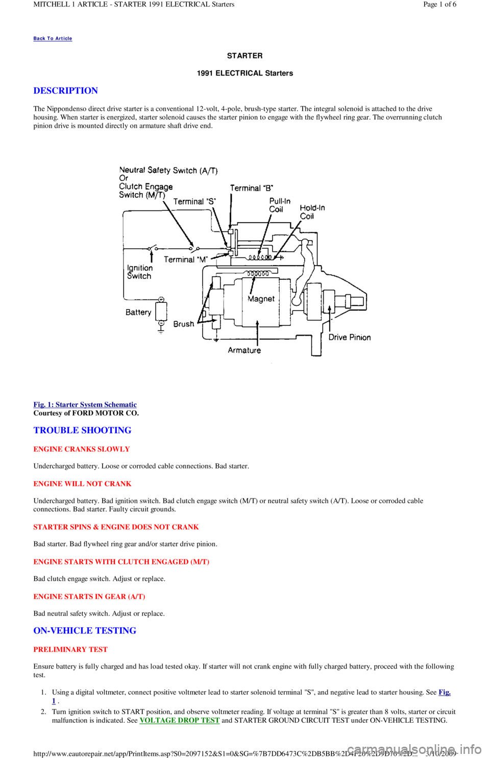
The Nippondenso direct drive starter is a conventional 12-volt, 4-pole, brush-type starter. The integral solenoid is attached to the drive
housing. When starter is energized, starter solenoid causes the starter pinion to engage with the flywheel ring gear. The overrunning clutch
pinion drive is mounted directly on armature shaft drive end.
Fig. 1: Starter System Schematic
Courtesy of FORD MOTOR CO.
TROUBLE SHOOTING
ENGINE CRANKS SLOWLY
Undercharged battery. Loose or corroded cable connections. Bad starter.
ENGINE WILL NOT CRANK
Undercharged battery. Bad ignition switch. Bad clutch engage switch (M/T) or neutral safety switch (A/T). Loose or corroded cable
connections. Bad starter. Faulty circuit grounds.
STARTER SPINS & ENGINE DOES NOT CRANK
Bad starter. Bad flywheel ring gear and/or starter drive pinion.
ENGINE STARTS WITH CLUTCH ENGAGED (M/T)
Bad clutch engage switch. Adjust or replace.
ENGINE STARTS IN GEAR (A/T)
Bad neutral safety switch. Adjust or replace.
ON-VEHICLE TESTING
PRELIMINARY TEST
Ensure battery is fully charged and has load tested okay. If starter will not crank engine with fully charged battery, proceed with the following
test.
1. Using a digital voltmeter, connect positive voltmeter lead to starter solenoid terminal "S", and negative lead to starter housing. See Fig.
1 .
2. Turn ignition switch to START position, and observe voltmeter reading. If voltage at terminal "S" is greater than 8 volts, starter or circuit
malfunction is indicated. See VOLTAGE DROP TEST
and STARTER GROUND CIRCUIT TEST under ON-VEHICLE TESTING.
Page 1 of 6 MITCHELL 1 ARTICLE - STARTER 1991 ELECTRICAL Starters
3/10/2009 http://www.eautorepair.net/app/PrintItems.asp?S0=2097152&S1=0&SG=%7B7DD6473C%2DB5BB%2D4F20%2D9D70%2D
...
Page 53 of 454
3. If voltage is not present or is less than 8 volts at starter solenoid terminal "S", malfunction in circuit to terminal "S" is indicated. Proceed
to the following tests.
IGNITION SWITCH TEST
1. Locate ignition switch connector under dash. Using a 12-volt test light or voltmeter, ensure voltage is present on Black/Yellow wire
when ignition switch is turned to RUN or ON position. This will verify proper operation of ignition switch.
2. If there is no voltage on Black/Yellow wire, the problem is either ignition switch or circuit between battery and ignition switch.
CLUTCH ENGAGE SWITCH (M/T) TEST
Unplug clutch engage switch from main wiring harness. Using an ohmmeter, check for continuity across switch terminals. Continuity should
exist when switch plunger is pushed in and should not exist when switch plunger is released. If clutch engage switch does not operate as
specified, replace switch.
NEUTRAL SAFETY SWITCH (A/T) TEST
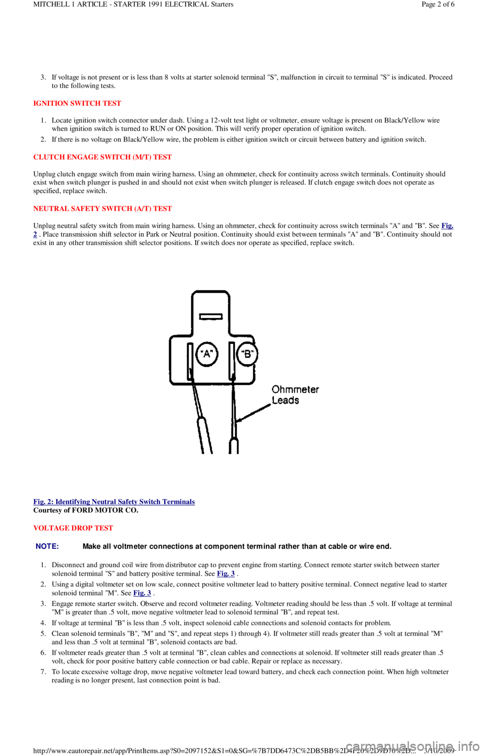
Unplug neutral safety switch from main wiring harness. Using an ohmmeter, check for continuity across switch terminals "A" and "B". See Fig.
2 . Place transmission shift selector in Park or Neutral position. Continuity should exist between terminals "A" and "B". Continuity should not
exist in any other transmission shift selector positions. If switch does nor operate as specified, replace switch.
Fig. 2: Identifying Neutral Safety Switch Terminals
Courtesy of FORD MOTOR CO.
VOLTAGE DROP TEST
1. Disconnect and ground coil wire from distributor cap to prevent engine from starting. Connect remote starter switch between starter
solenoid terminal "S" and battery positive terminal. See Fig. 3
.
2. Using a digital voltmeter set on low scale, connect positive voltmeter lead to battery positive terminal. Connect negative lead to starter
solenoid terminal "M". See Fig. 3
.
3. Engage remote starter switch. Observe and record voltmeter reading. Voltmeter reading should be less than .5 volt. If voltage at terminal
"M" is greater than .5 volt, move negative voltmeter lead to solenoid terminal "B", and repeat test.
4. If voltage at terminal "B" is less than .5 volt, inspect solenoid cable connections and solenoid contacts for problem.
5 . Cl ean so l en o id t ermin al s "B", "M" an d "S", an d rep eat st ep s 1 ) through 4). If voltmeter still reads greater than .5 volt at termin al "M"
and less than .5 volt at terminal "B", solenoid contacts are bad.
6. If voltmeter reads greater than .5 volt at terminal "B", clean cables and connections at solenoid. If voltmeter still reads greater than .5
volt, check for poor positive battery cable connection or bad cable. Repair or replace as necessary.
7. To locate excessive voltage drop, move negative voltmeter lead toward battery, and check each connection point. When high voltmeter
reading is no longer present, last connection point is bad.
NOTE:Make all voltm eter connections at com ponent term inal rather than at cable or wire end.
Page 2 of 6 MITCHELL 1 ARTICLE - STARTER 1991 ELECTRICAL Starters
3/10/2009 http://www.eautorepair.net/app/PrintItems.asp?S0=2097152&S1=0&SG=%7B7DD6473C%2DB5BB%2D4F20%2D9D70%2D
...
Page 54 of 454
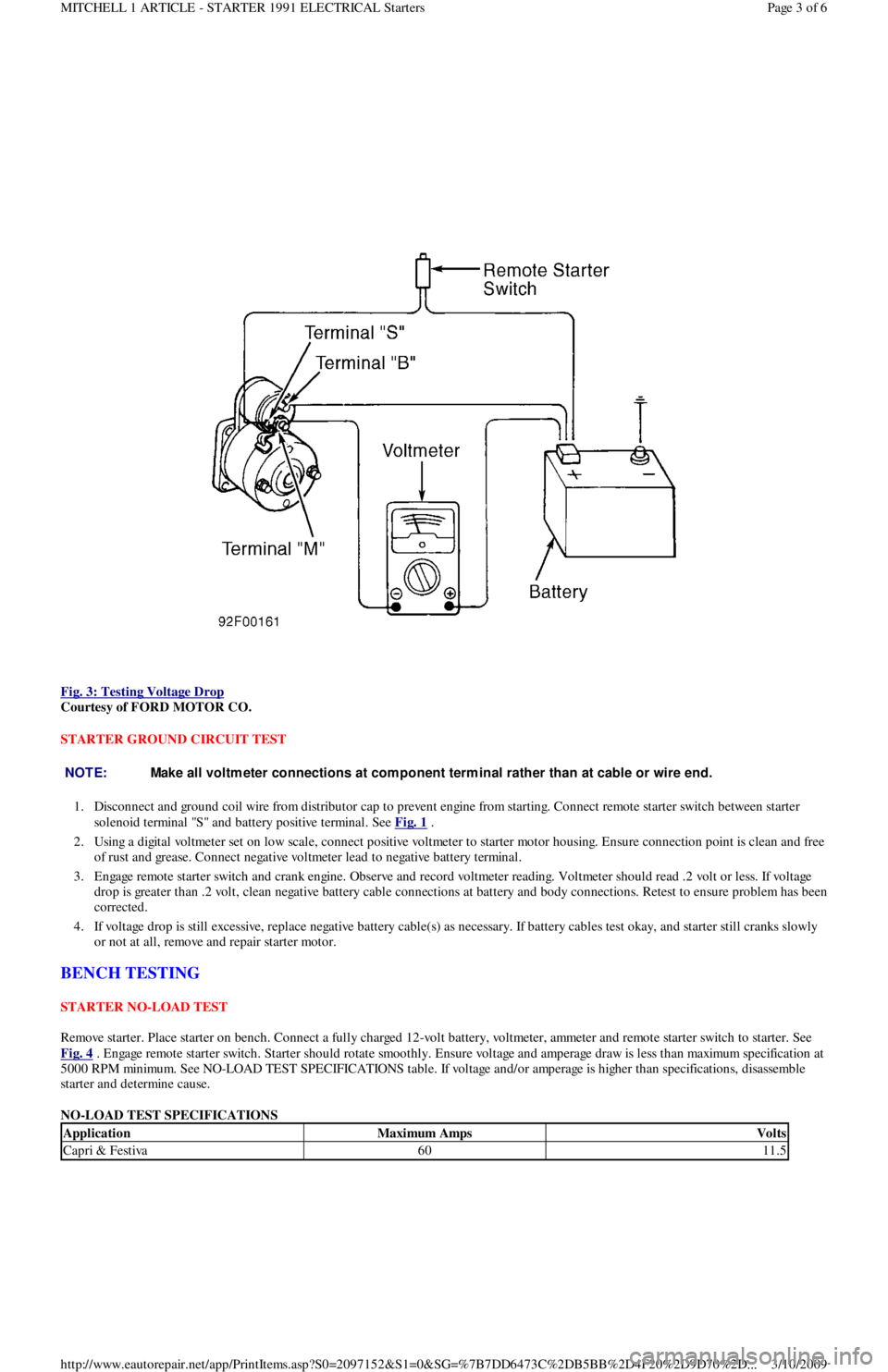
Fig. 3: Testing Voltage Drop
Courtesy of FORD MOTOR CO.
STARTER GROUND CIRCUIT TEST
1. Disconnect and ground coil wire from distributor cap to prevent engine from starting. Connect remote starter switch between starter
solenoid terminal "S" and battery positive terminal. See Fig. 1
.
2. Using a digital voltmeter set on low scale, connect positive voltmeter to starter motor housing. Ensure connection point is clean and free
of rust and grease. Connect negative voltmeter lead to negative battery terminal.
3. Engage remote starter switch and crank engine. Observe and record voltmeter reading. Voltmeter should read .2 volt or less. If voltage
drop is greater than .2 volt, clean negative battery cable connections at battery and body connections. Retest to ensure problem has been
corrected.
4. If voltage drop is still excessive, replace negative battery cable(s) as necessary. If battery cables test okay, and starter still cranks slowly
or not at all, remove and repair starter motor.
BENCH TESTING
STARTER NO-LOAD TEST
Remove starter. Place starter on bench. Connect a fully charged 12-volt battery, voltmeter, ammeter and remote starter switch to starter. See
Fig. 4
. Engage remote starter switch. Starter should rotate smoothly. Ensure voltage and amperage draw is less than maximum specification at
5000 RPM minimum. See NO-LOAD TEST SPECIFICATIONS table. If voltage and/or amperage is higher than specifications, disassemble
starter and determine cause.
NO-LOAD TEST SPECIFICATIONS
NOTE:Make all voltm eter connections at com ponent term inal rather than at cable or wire end.
ApplicationMaximum AmpsVolts
Capri & Festiva6011.5
Page 3 of 6 MITCHELL 1 ARTICLE - STARTER 1991 ELECTRICAL Starters
3/10/2009 http://www.eautorepair.net/app/PrintItems.asp?S0=2097152&S1=0&SG=%7B7DD6473C%2DB5BB%2D4F20%2D9D70%2D
...
Page 55 of 454
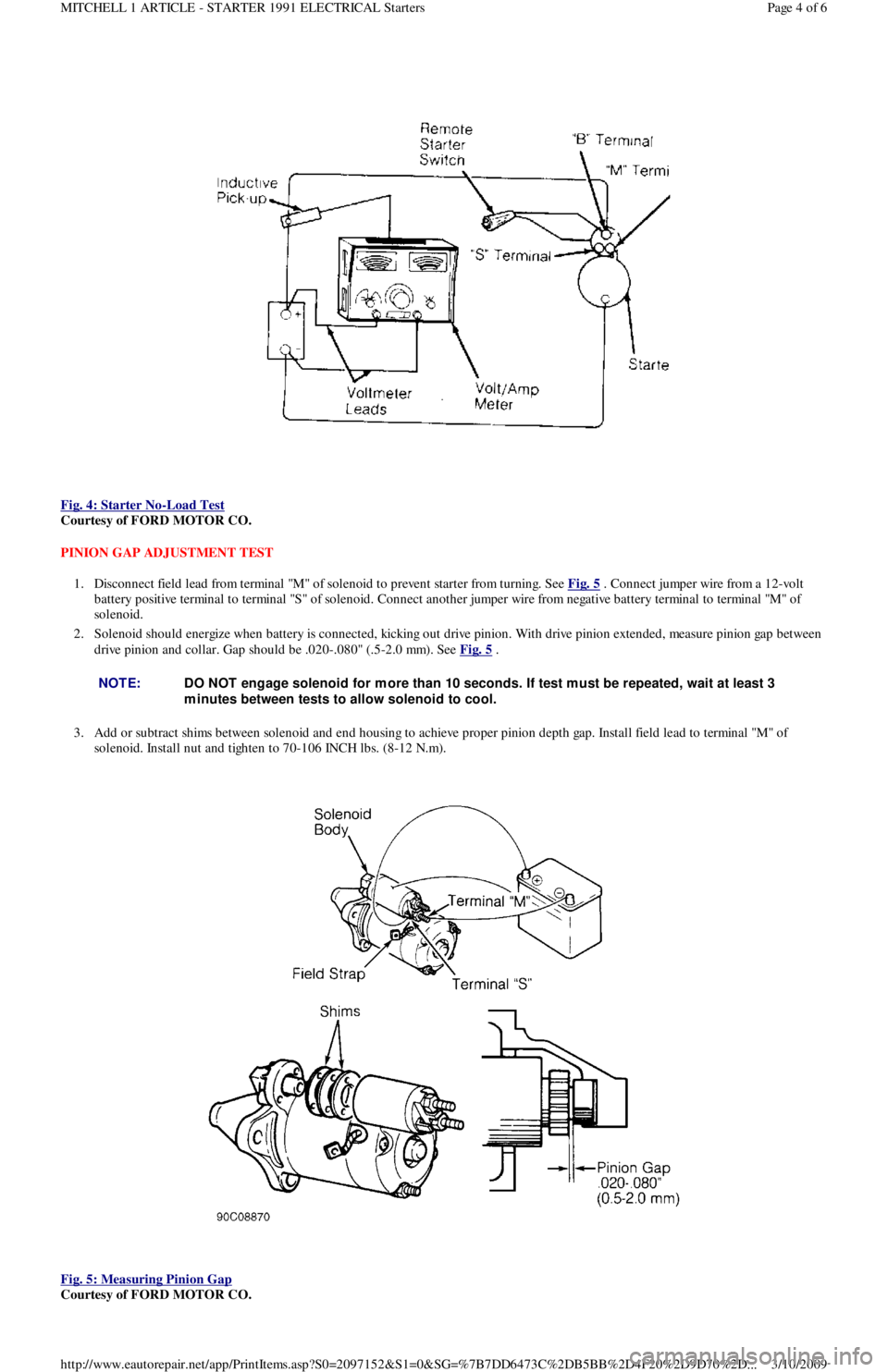
Fig. 4: Starter No
-Load Test
Courtesy of FORD MOTOR CO.
PINION GAP ADJUSTMENT TEST
1. Disconnect field lead from terminal "M" of solenoid to prevent starter from turning. See Fig. 5
. Connect jumper wire from a 12-volt
battery positive terminal to terminal "S" of solenoid. Connect another jumper wire from negative battery terminal to terminal "M" of
solenoid.
2. Solenoid should energize when battery is connected, kicking out drive pinion. With drive pinion extended, measure pinion gap between
drive pinion and collar. Gap should be .020-.080" (.5-2.0 mm). See Fig. 5
.
3. Add or subtract shims between solenoid and end housing to achieve proper pinion depth gap. Install field lead to terminal "M" of
solenoid. Install nut and tighten to 70-106 INCH lbs. (8-12 N.m).
Fig. 5: Measuring Pinion Gap
Courtesy of FORD MOTOR CO.
NOTE:DO NOT engage solenoid for m ore than 10 seconds. If test m ust be repeated, wait at least 3
m inutes between tests to allow solenoid to cool.
Page 4 of 6 MITCHELL 1 ARTICLE - STARTER 1991 ELECTRICAL Starters
3/10/2009 http://www.eautorepair.net/app/PrintItems.asp?S0=2097152&S1=0&SG=%7B7DD6473C%2DB5BB%2D4F20%2D9D70%2D
...
Page 66 of 454

Autolamp Control RelayHeadlight Systems; Daytime Running Lights
Automatic Shutdown (ASD) RelayEngine Performance; Generators & Regulators
Autostick SwitchEngine Performance
Auxiliary Battery RelayGenerators & Regulators
Back-Up LightsBack-Up Lights; Exterior Lights
Barometric (BARO) Pressure SensorEngine Performance
BatteryPower Distribution
Battery Temperature SensorEngine Performance
Body Control ModuleBody Control Computer; Anti-Theft System; Daytime Running
Lights; Engine Performance; Headlight Systems; Warning Systems
Boost Control SolenoidEngine Performance
Boost SensorEngine Performance
Brake Fluid Level SwitchAnalog Instrument Panels
Brake On/Off (BOO) SwitchCruise Control Systems; Engine Performance; Shift Interlock
Systems
Buzzer ModuleWarning Systems
Camshaft Position (CMP) SensorEngine Performance
Central Control ModuleAnti-Theft System
ClockspringAir Bag Restraint System; Cruise Control Systems; Steering
Column Switches
Clutch Pedal Position SwitchStarters
Clutch Start SwitchStarters
Combination MeterAnalog Instrument Panels
Constant Control Relay Module (CCRM)Engine Performance; Electric Cooling Fans
Convenience CenterPower Distribution; Illumination/Interior Lights
Convertible Top MotorPower Convertible Top
Convertible Top SwitchPower Convertible Top
Crankshaft Position (CKP) SensorEngine Performance
Cruise Control ModuleCruise Control Systems
Cruise Control SwitchCruise Control Systems
Condenser Fan Relay(s)Electric Cooling Fans
Data Link Connector (DLC)Engine Performance
Da yt ime R u n n in g Ligh t s M o d u l eDaytime Running Lights; Exterior Lights
Defogger RelayRear Window Defogger
Diagnostic Energy Reserve Module (DERM)Air Bag Restraint System
Discriminating Sensor (Air Bag)Air Bag Restraint System
DistributorEngine Performance
Door Lock ActuatorsPower Door Locks; Remote Keyless Entry
Door Lock Relay(s)Power Door Locks
Electrochromic MirrorPower Mirrors
Electronic Level Control (ELC) Height SensorElectronic Suspension
Electronic Level Control (ELC) ModuleElectronic Suspension
Engine Coolant Temperature (ECT) Sending UnitAnalog Instrument Panels
Engine Coolant Temperature (ECT) SensorEngine Performance
Engine Control ModuleEngine Performance; Generators & Regulators; Starters
ETACS ECUWarning Systems; Power Windows; Remote Keyless Entry
Evaporative (EVAP) Emissions CanisterEngine Performance
EVAP Canister Purge SolenoidEngine Performance
EVAP Canister Vent SolenoidEngine Performance
Exhaust Gas Recirculation (EGR) ValveEngine Performance
Fuel Tank Vacuum SensorEngine Performance
F o g Ligh t sHeadlight Systems; Daytime Running Lights
F o g Ligh t R e l a yHeadlight Systems; Daytime Running Lights
Fuel Door Release SolenoidPower Fuel Door Release
Fuel Gauge Sending UnitAnalog Instrument Panels
Fuel InjectorsEngine Performance
Fuel PumpEngine Performance
Fuel Pump RelayEngine Performance; Power Distribution
Fuse/Relay BlockPower Distribution
Fusible LinksPower Distribution; Generators & Regulators; Starters
GeneratorGenerators & Regulators; Engine Performance; Power Distribution
Generic Electronic Module (GEM)Body Control Modules; Electronic Suspension
Glow Plug RelayEngine Performance
Glow PlugsEngine Performance
GroundsGround Distribution
Headlight Door ModuleHeadlight Doors
Headlight RelayHeadlight Systems; Daytime Running Lights
HeadlightsHeadlight Systems; Daytime Running Lights
Heated Oxygen Sensor(s) (HO2S)Engine Performance
Heated Windshield Control ModuleHeated Windshields
Page 4 of 6 MITCHELL 1 ARTICLE - GENERAL INFORMATION Using Mitchell1's Wiring Diagrams
3/10/2009 http://www.eautorepair.net/app/PrintItems.asp?S0=2097152&S1=0&SG=%7B959286D2%2D3A85%2D4BFC%2D9C5C%2D
...
Page 69 of 454
Back To Article
WIRING DIAGRAMS
1991 WIRING DIAGRAMS Ford Motor Co.
IDENTIFICATION
COMPONENT LOCATION MENU
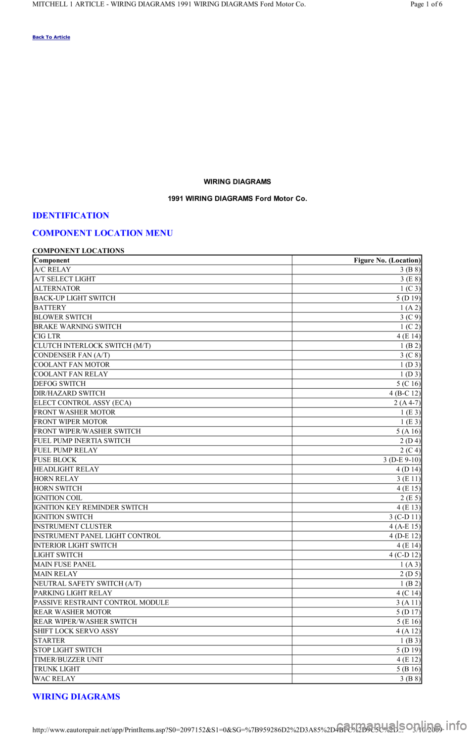
COMPONENT LOCATIONS
WIRING DIAGRAMS
ComponentFigure No. (Location)
A/C RELAY3 (B 8)
A/T SELECT LIGHT3 (E 8)
ALTERNATOR1 (C 3)
BACK-UP LIGHT SWITCH5 (D 19)
BATTERY1 (A 2)
BLOWER SWITCH3 (C 9)
BRAKE WARNING SWITCH1 (C 2)
CIG LTR4 (E 14)
CLUTCH INTERLOCK SWITCH (M/T)1 (B 2)
CONDENSER FAN (A/T)3 (C 8)
COOLANT FAN MOTOR1 (D 3)
COOLANT FAN RELAY1 (D 3)
DEFOG SWITCH5 (C 16)
DIR/HAZARD SWITCH4 (B-C 12)
ELECT CONTROL ASSY (ECA)2 (A 4-7)
FRONT WASHER MOTOR1 (E 3)
FRONT WIPER MOTOR1 (E 3)
FRONT WIPER/WASHER SWITCH5 (A 16)
FUEL PUMP INERTIA SWITCH2 (D 4)
FUEL PUMP RELAY2 (C 4)
FUSE BLOCK3 (D-E 9-10)
HEADLIGHT RELAY4 (D 14)
HORN RELAY3 (E 11)
HORN SWITCH4 (E 15)
IGNITION COIL2 (E 5)
IGNITION KEY REMINDER SWITCH4 (E 13)
IGNITION SWITCH3 (C-D 11)
INSTRUMENT CLUSTER4 (A-E 15)
INSTRUMENT PANEL LIGHT CONTROL4 (D-E 12)
INTERIOR LIGHT SWITCH4 (E 14)
LIGHT SWITCH4 (C-D 12)
MAIN FUSE PANEL1 (A 3)
MAIN RELAY2 (D 5)
NEUTRAL SAFETY SWITCH (A/T)1 (B 2)
PARKING LIGHT RELAY4 (C 14)
PASSIVE RESTRAINT CONTROL MODULE3 (A 11)
REAR WASHER MOTOR5 (D 17)
REAR WIPER/WASHER SWITCH5 (E 16)
SHIFT LOCK SERVO ASSY4 (A 12)
STARTER1 (B 3)
STOP LIGHT SWITCH5 (D 19)
TIMER/BUZZER UNIT4 (E 12)
TRUNK LIGHT5 (B 16)
WAC RELAY3 (B 8)
Page 1 of 6 MITCHELL 1 ARTICLE - WIRING DIAGRAMS 1991 WIRING DIAGRAMS Ford Motor Co.
3/10/2009 http://www.eautorepair.net/app/PrintItems.asp?S0=2097152&S1=0&SG=%7B959286D2%2D3A85%2D4BFC%2D9C5C%2D
...