1991 FORD FESTIVA battery
[x] Cancel search: batteryPage 21 of 454
3. Position Steering Wheel Remover (T67L-3600-A) on steering wheel. Tighten bolt on remover until steering wheel is loose. Remove
steering wheel puller, steering wheel retaining bolt, and steering wheel.
Installation
1. Ensure front wheels are in straight-ahead position. Route clockspring wiring harness through steering wheel opening. Position steering
wheel on steering shaft and align reference marks.
2. Ensure clockspring wire is not pinched when positioning steering wheel. Install new steering wheel retaining bolt and tighten to
specification. See TORQUE SPECIFICATIONS table at end of article. Connect horn and speed control wiring connectors (if equipped)
to steering wheel.
3. Connect air bag module-to-clockspring connector. Install air bag module. Tighten air bag module retaining nuts to specification.
Activate SRS. See SAFETY PRECAUTIONS. Check AIR BAG light to ensure system is functioning properly.
Removal (Festiva)
From back of steering wheel, remove 2 screws securing horn pad. Disconnect horn wire from horn pad and remove pad. Remove steering
wheel nut. Scribe reference mark on steering shaft and steering wheel hub for reassembly. Using Steering Wheel Puller (T67L-3600-A),
remove steering wheel.
Installation
Position steering wheel on steering shaft and align reference marks. Be sure cutouts in rear cover engage turn signal canceling cam. To
complete installation, reverse removal procedure.
COMBINATION SW ITCH
Removal (Capri)
1. Disconnect negative battery cable. Remove lower steering column cover. Remove center access panel and trim cover under steering
column. Remove left side defroster connector tube. Remove steering column upper retaining bolts. Column will pivot downward and
rest on instrument panel brace.
2. Remove 2 switch retaining screws and remove switch. Grasp switch and lever and pull lever out of switch. Disconnect switch electrical
connectors and remove switch.
Installation
Align key with slot and install lever in switch assembly. Position switch on steering column and install retaining screws. To complete
installation, reverse removal procedure.
Removal (Festiva)
1. Disconnect negative battery cable. Remove steering wheel. See STEERING WHEEL & HORN PAD under REMOVAL &
INSTALLATION. Remove 4 screws from upper half of lower steering column cover and remove cover. Remove upper steering column
cover. Remove 5 clips from lower half of lower steering column cover and remove cover.
2. Release wiring harness clip and unplug 4 harness connectors from back of combination switch. From below steering column, loosen
band clamp securing switch hub to steering column jacket. Pull switch assembly from steering column.
Installation
Slide combination switch assembly onto steering column. Make sure switch assembly is seated and level against end of column jacket. To
complete installation, reverse removal procedure.
HEADLIGHT SWITCH
Removal & Installation (Capri)
1. Headlight off/on switch is located on left side of instrument panel bezel. Disconnect negative battery cable. Pull out center storage
compartment. Remove 2 upper screws, 2 lower screws and heater/radio bezel. Pull outward and remove trim covers located on both
sides of steering column.
2. Remove retaining screws and carefully pull instrument panel bezel partially away from dash. Disconnect electrical connector from
headlight switch. Depress tangs on both sides of switch and remove switch from bezel. To install, reverse removal procedure.
IGNITION SWITCH & LOCK CYLINDER
Removal (Capri)
1. Disconnect negative battery cable. Remove lower steering column cover. Remove center access panel and trim cover under steering
column. Remove left side defroster connector tube. Remove steering column upper retaining bolts. Column will pivot downward and
rest on instrument panel brace. steering colum n.
CAUT ION: Rem ove steering wheel carefully to avoid dam aging clockspring wiring, air bag m odule connector, or
accidentally turning clockspring. After steering wheel rem oval, tape clockspring in position to prevent
dam age and keep it from being turned accidentally.
CAUTION: Ensure that no wiring is pinched beneath steering colum n when lowered.
Page 4 of 5 MITCHELL 1 ARTICLE - STEERING COLUMN SWITCHES 1991 ACCESSORIES & SAFETY EQUIPMENT Ford Motor C
...
3/10/2009 http://www.eautorepair.net/app/PrintItems.asp?S0=2097152&S1=0&SG=%7B7DD6473C%2DB5BB%2D4F20%2D9D70%2D
...
Page 22 of 454
2. With ignition key inserted in lock assembly, rotate tumbler while pushing release pin with a .125" (3.17 mm) drift punch. Pull tumbler
assembly out of housing. Remove upper column cover. Remove column lock shield. Disconnect ignition switch electrical connector.
Remove switch retaining screws and remove switch.
Installation
Position ignition switch on column lock assembly. Make sure actuator pin of lock assembly fits into slot in ignition switch. To complete
installation, reverse removal procedure.
Removal & Installation (Festiva)
1. Disconnect negative battery cable. Remove 4 screws from upper half of lower steering column cover and remove cover. Remove upper
steering column cover. Remove 5 clips from lower half of lower steering column cover and remove cover.
2. Remove 4 steering column shield nuts and remove shield. Remove 2 shield bracket bolts and remove bracket. Remove air discharge duct
from below steering column. Remove steering column attaching nuts then lower steering column mounting bracket.
3. Remove tie strap securing key warning buzzer switch wires. Remove ignition switch attaching screw. Pull switch loose from switch
housing. Remove switch harness from routing clip and disconnect electrical connectors. Remove switch. To install, reverse removal
procedure.
TURN SIGNAL SWITCH
See COMBINATION SWITCH under REMOVAL & INSTALLATION.
WIPER SWITCH
Removal & Installation (Capri)
Remove center trim panel and lower steering column cover. Disconnect wiper switch electrical connector and pull wiring from routing clip.
Firmly grasp switch and lever and pull out to remove. To install, reverse removal procedure.
Removal & installation (Festiva)
See COMBINATION SWITCH under REMOVAL & INSTALLATION.
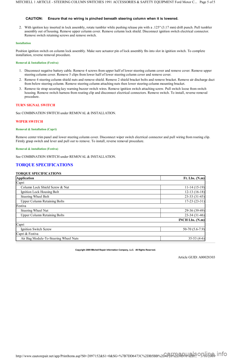
TORQUE SPECIFICATIONS
TORQUE SPECIFICATIONS CAUTION: Ensure that no wiring is pinched beneath steering colum n when it is lowered.
ApplicationFt. Lbs. (N.m)
Capri
Column Lock Shield Screw & Nut11-14 (15-19)
Ignition Lock Housing Bolt12-13 (16-18)
Steering Wheel Bolt23-33 (31-45)
Upper Column Retaining Bolts17-23 (23-31)
Festiva
Steering Wheel Nut29-36 (39-49)
Upper Column Retaining Bolts23-34 (31-46)
INCH Lbs. (N.m)
Capri
Ign it io n Swit ch Screw50-70 (5.6-7.9)
Capri & Festiva
Air Bag Module-To-Steering Wheel Nuts35-53 (4-6)
Copyr ight 2009 Mitchell Repair Information Company, LLC. All Rights Reserved.
Article GUID: A00028303
Page 5 of 5 MITCHELL 1 ARTICLE - STEERING COLUMN SWITCHES 1991 ACCESSORIES & SAFETY EQUIPMENT Ford Motor C
...
3/10/2009 http://www.eautorepair.net/app/PrintItems.asp?S0=2097152&S1=0&SG=%7B7DD6473C%2DB5BB%2D4F20%2D9D70%2D
...
Page 23 of 454
Back To Article
WIPER/WASHER SYST EM
1991 ACCESSORIES & SAFET Y EQUIPMENT Ford Motor Co. Wiper/Washer System s
DESCRIPTION & OPERATION
Capri and Festiva vehicles are equipped with a 2-speed wiper motor with an optional intermittent system. The Festiva rear wiper uses a single
speed wiper motor. Washer systems for both front and rear washers use pumps mounted near fluid reservoirs.
ADJUSTMENTS
W IPER ARM ADJUSTMENT
Remove wiper arm and blade assemblies from pivot shafts. Turn wiper switch on and allow wiper motor to cycle 2 to 3 times. Turn wiper
switch off to place pivot shafts in park position. Reinstall wiper arm and blade assemblies with tips of wiper blades at specified distance from
lower edge of windshield. See WIPER BLADE ADJUSTMENT SPECIFICATIONS
table. Tighten wiper arm retaining nut to 89-124
INCH Lbs. (10-14 N.m).
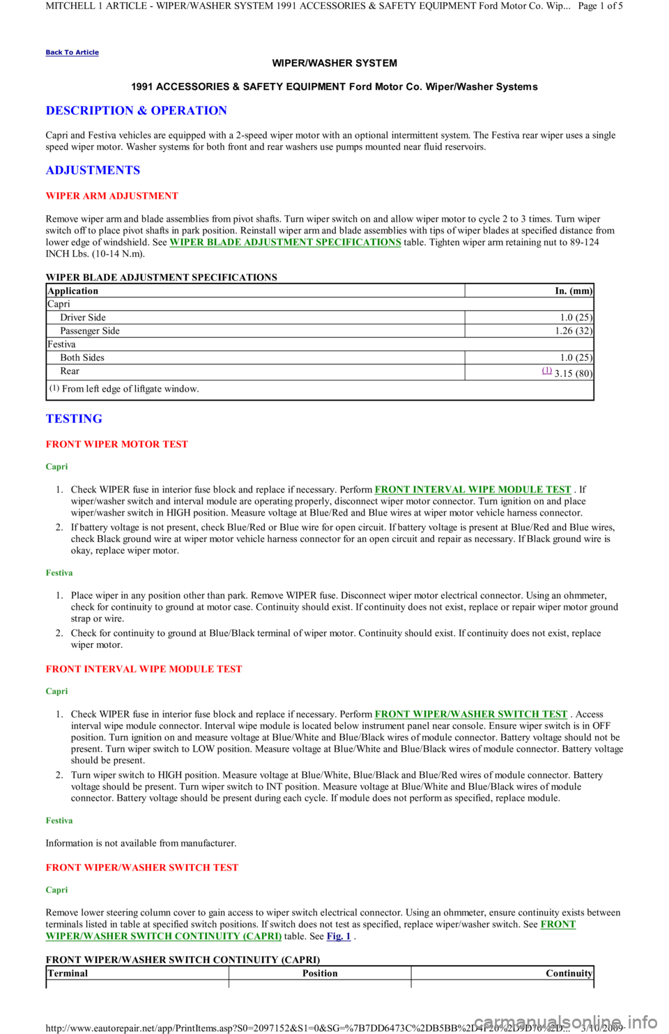
WIPER BLADE ADJUSTMENT SPECIFICATIONS
TESTING
FRONT WIPER MOTOR TEST
Capri
1. Check WIPER fuse in interior fuse block and replace if necessary. Perform FRONT INTERVAL WIPE MODULE TEST . If
wiper/washer switch and interval module are operating properly, disconnect wiper motor connector. Turn ignition on and place
wiper/washer switch in HIGH position. Measure voltage at Blue/Red and Blue wires at wiper motor vehicle harness connector.
2. If battery voltage is not present, check Blue/Red or Blue wire for open circuit. If battery voltage is present at Blue/Red and Blue wires,
check Black ground wire at wiper motor vehicle harness connector for an open circuit and repair as necessary. If Black ground wire is
okay, replace wiper motor.
Festiva
1. Place wiper in any position other than park. Remove WIPER fuse. Disconnect wiper motor electrical connector. Using an ohmmeter,
check for continuity to ground at motor case. Continuity should exist. If continuity does not exist, replace or repair wiper motor ground
strap or wire.
2. Check for continuity to ground at Blue/Black terminal of wiper motor. Continuity should exist. If continuity does not exist, replace
wiper motor.
FRONT INTERVAL WIPE MODULE TEST
Capri
1. Check WIPER fuse in interior fuse block and replace if necessary. Perform FRONT WIPER/WASHER SWITCH TEST . Access
interval wipe module connector. Interval wipe module is located below instrument panel near console. Ensure wiper switch is in OFF
position. Turn ignition on and measure voltage at Blue/White and Blue/Black wires of module connector. Battery voltage should not be
present. Turn wiper switch to LOW position. Measure voltage at Blue/White and Blue/Black wires of module connector. Battery voltage
should be present.
2. Turn wiper switch to HIGH position. Measure voltage at Blue/White, Blue/Black and Blue/Red wires of module connector. Battery
voltage should be present. Turn wiper switch to INT position. Measure voltage at Blue/White and Blue/Black wires of module
connector. Battery voltage should be present during each cycle. If module does not perform as specified, replace module.
Festiva
Information is not available from manufacturer.
FRONT WIPER/WASHER SWITCH TEST
Capri
Remove lower steering column cover to gain access to wiper switch electrical connector. Using an ohmmeter, ensure continuity exists between
terminals listed in table at specified switch positions. If switch does not test as specified, replace wiper/washer switch. See FRONT
WIPER/WASHER SWITCH CONTINUITY (CAPRI) table. See Fig. 1 .
FRONT WIPER/WASHER SWITCH CONTINUITY (CAPRI)
ApplicationIn. (mm)
Capri
Driver Side1.0 (25)
Passenger Side1.26 (32)
Festiva
Both Sides1.0 (25)
Rear(1) 3.15 (80)
(1)From left edge of liftgate window.
TerminalPositionContinuity
Page 1 of 5 MITCHELL 1 ARTICLE - WIPER/WASHER SYSTEM 1991 ACCESSORIES & SAFETY EQUIPMENT Ford Motor Co. Wip
...
3/10/2009 http://www.eautorepair.net/app/PrintItems.asp?S0=2097152&S1=0&SG=%7B7DD6473C%2DB5BB%2D4F20%2D9D70%2D
...
Page 25 of 454
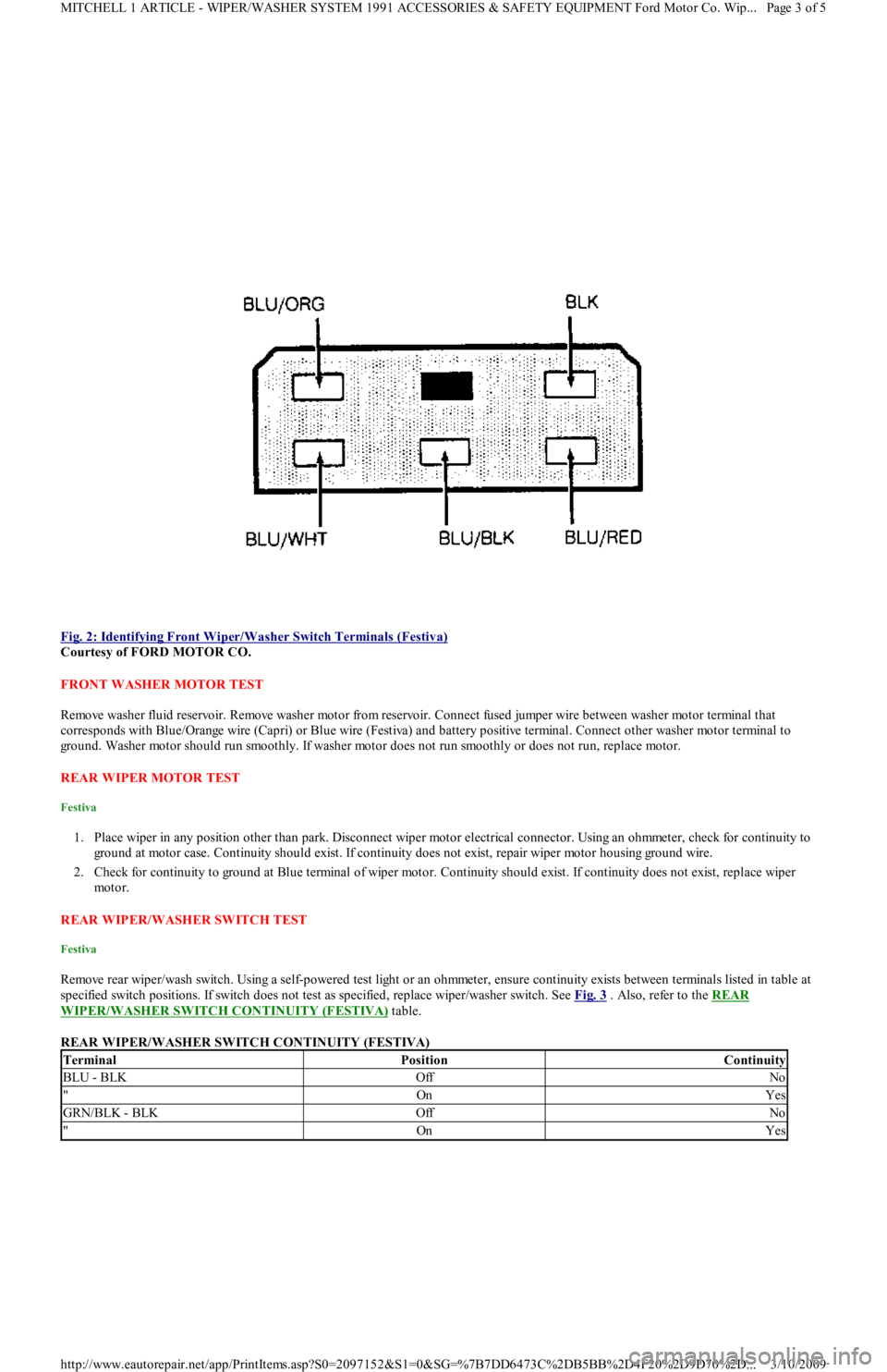
Fig. 2: Identifying Front Wiper/Washer Switch Terminals (Festiva)
Courtesy of FORD MOTOR CO.
FRONT WASHER MOTOR TEST
Remove washer fluid reservoir. Remove washer motor from reservoir. Connect fused jumper wire between washer motor terminal that
corresponds with Blue/Orange wire (Capri) or Blue wire (Festiva) and battery positive terminal. Connect other washer motor terminal to
ground. Washer motor should run smoothly. If washer motor does not run smoothly or does not run, replace motor.
REAR WIPER MOTOR TEST
Festiva
1. Place wiper in any position other than park. Disconnect wiper motor electrical connector. Using an ohmmeter, check for continuity to
ground at motor case. Continuity should exist. If continuity does not exist, repair wiper motor housing ground wire.
2. Check for continuity to ground at Blue terminal of wiper motor. Continuity should exist. If continuity does not exist, replace wiper
mo t o r.
REAR WIPER/WASHER SWITCH TEST
Festiva
Remove rear wiper/wash switch. Using a self-powered test light or an ohmmeter, ensure continuity exists between terminals listed in table at
specified switch positions. If switch does not test as specified, replace wiper/washer switch. See Fig. 3
. Also, refer to the REAR
WIPER/WASHER SWITCH CONTINUITY (FESTIVA) table.
REAR WIPER/WASHER SWITCH CONTINUITY (FESTIVA)
TerminalPositionContinuity
BLU - BLKOffNo
"OnYes
GRN/BLK - BLKOffNo
"OnYes
Page 3 of 5 MITCHELL 1 ARTICLE - WIPER/WASHER SYSTEM 1991 ACCESSORIES & SAFETY EQUIPMENT Ford Motor Co. Wip
...
3/10/2009 http://www.eautorepair.net/app/PrintItems.asp?S0=2097152&S1=0&SG=%7B7DD6473C%2DB5BB%2D4F20%2D9D70%2D
...
Page 26 of 454
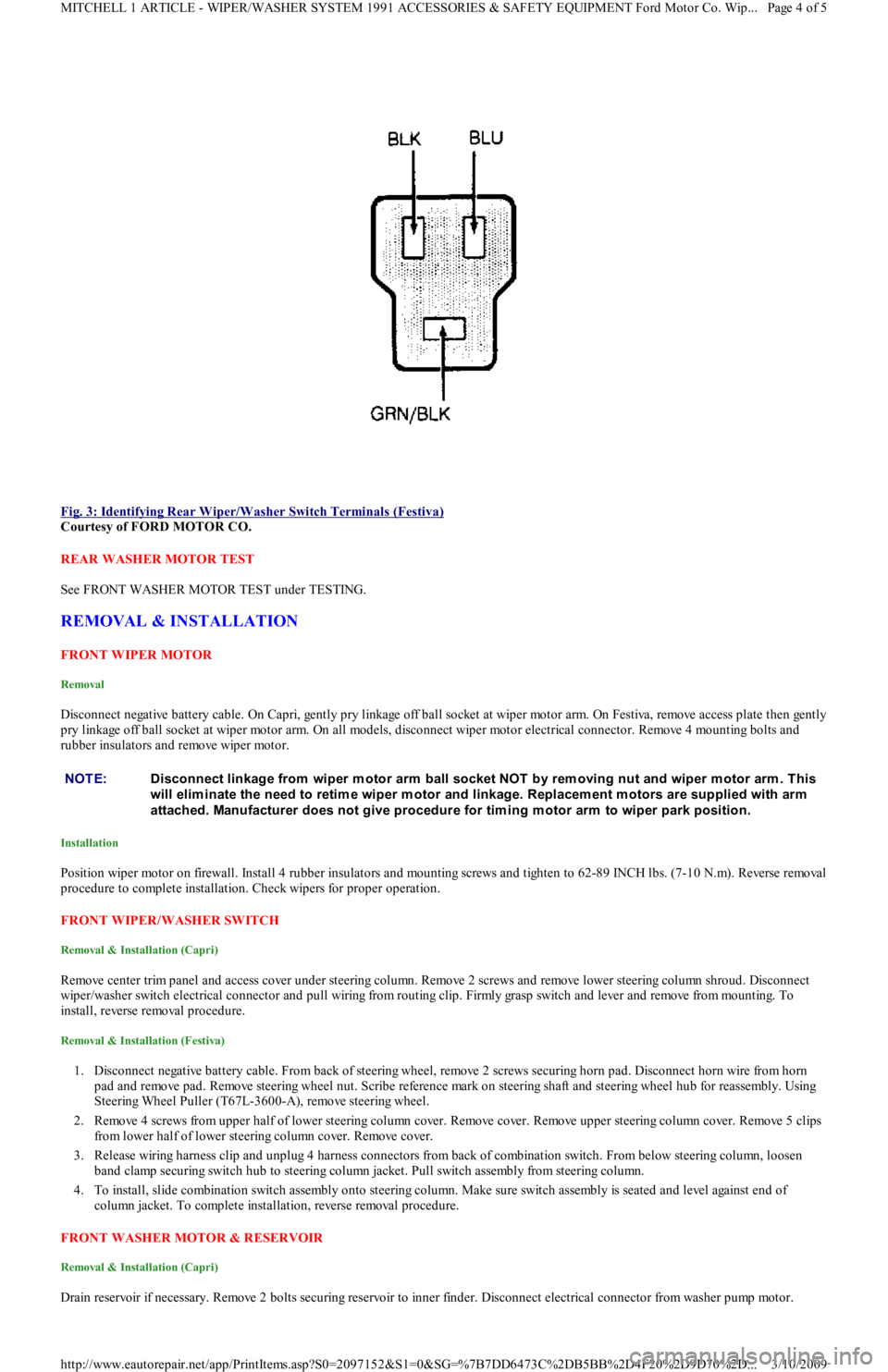
Fig. 3: Identifying Rear Wiper/Washer Switch Terminals (Festiva)
Courtesy of FORD MOTOR CO.
REAR WASHER MOTOR TEST
See FRONT WASHER MOTOR TEST under TESTING.
REMOVAL & INSTALLATION
FRONT WIPER MOTOR
Removal
Disconnect negative battery cable. On Capri, gently pry linkage off ball socket at wiper motor arm. On Festiva, remove access plate then gently
pry linkage off ball socket at wiper motor arm. On all models, disconnect wiper motor electrical connector. Remove 4 mounting bolts and
rubber insulators and remove wiper motor.
Installation
Position wiper motor on firewall. Install 4 rubber insulators and mounting screws and tighten to 62-89 INCH lbs. (7-10 N.m). Reverse removal
procedure to complete installation. Check wipers for proper operation.
FRONT WIPER/WASHER SWITCH
Removal & Installation (Capri)
Remove center trim panel and access cover under steering column. Remove 2 screws and remove lower steering column shroud. Disconnect
wiper/washer switch electrical connector and pull wiring from routing clip. Firmly grasp switch and lever and remove from mounting. To
install, reverse removal procedure.
Removal & Installation (Festiva)
1. Disconnect negative battery cable. From back of steering wheel, remove 2 screws securing horn pad. Disconnect horn wire from horn
pad and remove pad. Remove steering wheel nut. Scribe reference mark on steering shaft and steering wheel hub for reassembly. Using
Steering Wheel Puller (T67L-3600-A), remove steering wheel.
2. Remove 4 screws from upper half of lower steering column cover. Remove cover. Remove upper steering column cover. Remove 5 clips
from lower half of lower steering column cover. Remove cover.
3. Release wiring harness clip and unplug 4 harness connectors from back of combination switch. From below steering column, loosen
band clamp securing switch hub to steering column jacket. Pull switch assembly from steering column.
4. To install, slide combination switch assembly onto steering column. Make sure switch assembly is seated and level against end of
column jacket. To complete installation, reverse removal procedure.
FRONT WASHER MOTOR & RESERVOIR
Removal & Installation (Capri)
Drain reservoir if necessary. Remove 2 bolts securing reservoir to inner finder. Disconnect electrical connector from washer pump mo t o r.
NOTE:Disconnect linkage from wiper m otor arm ball socket NOT by rem oving nut and wiper m otor arm . This
will elim inate the need to retim e wiper m otor and linkage. Replacem ent m otors are supplied with arm
attached. Manufacturer does not give procedure for tim ing m otor arm to wiper park position.
Page 4 of 5 MITCHELL 1 ARTICLE - WIPER/WASHER SYSTEM 1991 ACCESSORIES & SAFETY EQUIPMENT Ford Motor Co. Wip
...
3/10/2009 http://www.eautorepair.net/app/PrintItems.asp?S0=2097152&S1=0&SG=%7B7DD6473C%2DB5BB%2D4F20%2D9D70%2D
...
Page 27 of 454
Disconnect fluid lines and remove reservoir. To install, reverse removal procedure.
Removal & Installation (Festiva)
1. Disconnect negative battery cable. Remove washer reservoir filler neck attaching bolt. Remove coolant expansion reservoir. Disconnect
washer pump electrical connector. Remove left front splash shield.
2. Disconnect washer pump fluid lines and detach lines from reservoir clips. Remove reservoir attaching nuts and bolt. Detach washer
reservoir from filler neck and remove reservoir. To install, reverse removal procedure.
REAR WIPER MOTOR
Removal & Installation (Festiva)
Remove rear wiper arm and blade assembly. Remove boot from outer bushing attaching nut. Remove outer bushing attaching nut and remove
outer bushing. Remove liftgate trim panel. Disconnect wiper motor electrical connector. Remove 4 wiper motor mounting bolts and remove
motor. To install, reverse removal procedure.
REAR WIPER/WASHER SWITCH
Removal & Installation (Festiva)
Disconnect negative battery cable. Remove steering column covers. Remove screws securing instrument panel bezel to instrument panel. Pull
instrument bezel away from instrument panel. Disconnect electrical connectors from switches in bezel. Compress wiper/washer switch lock
tabs and remove switch from bezel. To install, reverse removal procedure.
REAR WASHER MOTOR & RESERVOIR
Removal & Installation (Festiva)
Open liftgate and detach reservoir cap. Remove rear quarter trim panel. Remove reservoir mounting bolts. Disconnect electrical connector
from washer pump. Disconnect fluid lines. Remove reservoir. To install, reverse removal procedure.
TORQUE SPECIFICATIONS
TORQUE SPECIFICATIONS
WIRING DIAGRAMS
See appropriate chassis wiring diagram in the WIRING DIAGRAMS Section.
ApplicationINCH Lbs. (N.m)
Front Wiper Arm Retaining Nut89-124 (10-14)
Front Wiper Motor Mounting Bolts62-89 (7-10)
Rear Outer Bushing Retaining Nut27-44 (3-5)
Rear Wiper Arm Nut53-62 (6-7)
Rear Wiper Motor Mounting Bolts71-97 (8-11)
Copyr ight 2009 Mitchell Repair Information Company, LLC. All Rights Reserved.
Article GUID: A00028304
Page 5 of 5 MITCHELL 1 ARTICLE - WIPER/WASHER SYSTEM 1991 ACCESSORIES & SAFETY EQUIPMENT Ford Motor Co. Wip
...
3/10/2009 http://www.eautorepair.net/app/PrintItems.asp?S0=2097152&S1=0&SG=%7B7DD6473C%2DB5BB%2D4F20%2D9D70%2D
...
Page 43 of 454
Back To Article
ALTERNATOR & REGULATOR
1991 ELECT RICAL Alternators & Regulators
DESCRIPTION
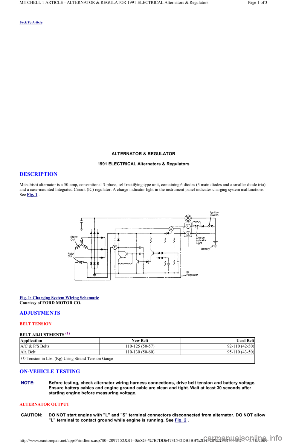
Mitsubishi alternator is a 50-amp, conventional 3-phase, self-rectifying type unit, containing 6 diodes (3 main diodes and a smaller diode trio)
and a case-mounted Integrated Circuit (IC) regulator. A charge indicator light in the instrument panel indicates charging system mal fu n ct io n s.
See Fig. 1
.
Fig. 1: Charging System Wiring Schematic
Courtesy of FORD MOTOR CO.
ADJUSTMENTS
BELT TENSION
BELT ADJUSTMENTS
(1)
ON-VEHICLE TESTING
ALTERNATOR OUTPUT
ApplicationNew BeltUsed Belt
A/C & P/S Belts110-125 (50-57)92-110 (42-50)
Alt. Belt110-130 (50-60)95-110 (43-50)
(1)Tension in Lbs. (Kg) Using Strand Tension Gauge
NOTE:Before testing, check alternator wiring harness connections, drive belt tension and battery voltage.
Ensure battery cables and engine ground cable are clean and tight. Wait at least 30 seconds after
starting engine before m easuring voltage.
CAUT ION: DO NOT start engine with "L" and "S" term inal connectors disconnected from alternator. DO NOT allow
"L" term inal to contact ground while engine is running. See Fig. 2
.
Page 1 of 3 MITCHELL 1 ARTICLE - ALTERNATOR & REGULATOR 1991 ELECTRICAL Alternators & Regulators
3/10/2009 http://www.eautorepair.net/app/PrintItems.asp?S0=2097152&S1=0&SG=%7B7DD6473C%2DB5BB%2D4F20%2D9D70%2D
...
Page 44 of 454
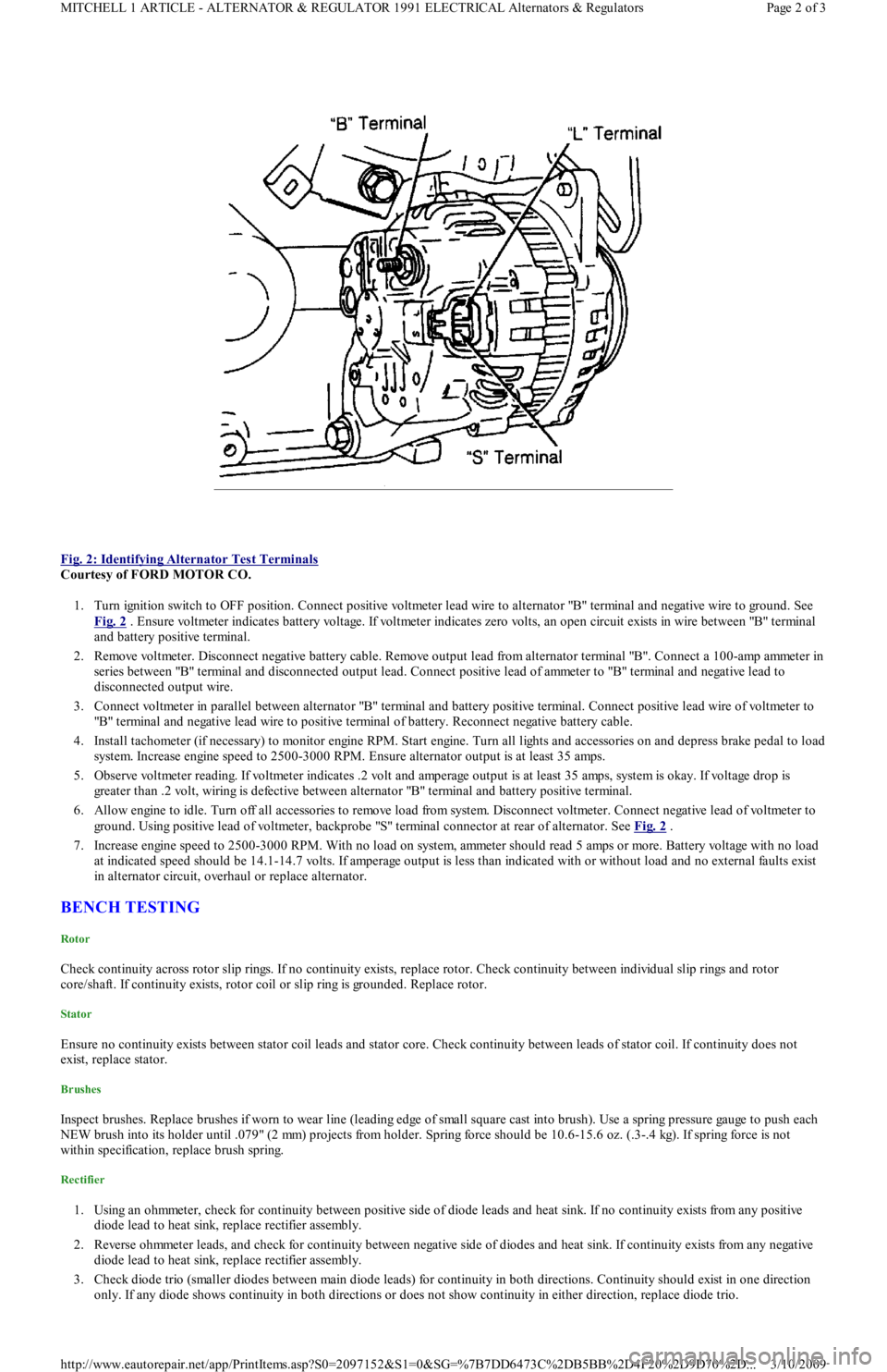
Fig. 2: Identifying Alternator Test Terminals
Courtesy of FORD MOTOR CO.
1. Turn ignition switch to OFF position. Connect positive voltmeter lead wire to alternator "B" terminal and negative wire to ground. See
Fig. 2
. Ensure voltmeter indicates battery voltage. If voltmeter indicates zero volts, an open circuit exists in wire between "B" terminal
and battery positive terminal.
2. Remove voltmeter. Disconnect negative battery cable. Remove output lead from alternator terminal "B". Connect a 100-amp ammeter in
series between "B" terminal and disconnected output lead. Connect positive lead of ammeter to "B" terminal and negative lead to
disconnected output wire.
3. Connect voltmeter in parallel between alternator "B" terminal and battery positive terminal. Connect positive lead wire of voltmeter to
"B" terminal and negative lead wire to positive terminal of battery. Reconnect negative battery cable.
4. Install tachometer (if necessary) to monitor engine RPM. Start engine. Turn all lights and accessories on and depress brake pedal to load
system. Increase engine speed to 2500-3000 RPM. Ensure alternator output is at least 35 amps.
5. Observe voltmeter reading. If voltmeter indicates .2 volt and amperage output is at least 35 amps, system is okay. If voltage drop is
greater than .2 volt, wiring is defective between alternator "B" terminal and battery positive terminal.
6. Allow engine to idle. Turn off all accessories to remove load from system. Disconnect voltmeter. Connect negative lead of voltmeter to
ground. Using positive lead of voltmeter, backprobe "S" terminal connector at rear of alternator. See Fig. 2
.
7. Increase engine speed to 2500-3000 RPM. With no load on system, ammeter should read 5 amps or more. Battery voltage with no load
at indicated speed should be 14.1-14.7 volts. If amperage output is less than indicated with or without load and no external faults exist
in alternator circuit, overhaul or replace alternator.
BENCH TESTING
Rotor
Check continuity across rotor slip rings. If no continuity exists, replace rotor. Check continuity between individual slip rings and rotor
core/shaft. If continuity exists, rotor coil or slip ring is grounded. Replace rotor.
Stator
Ensure no continuity exists between stator coil leads and stator core. Check continuity between leads of stator coil. If continuity does not
exist, replace stator.
Brushes
Inspect brushes. Replace brushes if worn to wear line (leading edge of small square cast into brush). Use a spring pressure gauge to push each
NEW brush into its holder until .079" (2 mm) projects from holder. Spring force should be 10.6-15.6 oz. (.3-.4 kg). If spring force is not
within specification, replace brush spring.
Rectifier
1. Using an ohmmeter, check for continuity between positive side of diode leads and heat sink. If no continuity exists from any positive
diode lead to heat sink, replace rectifier assembly.
2. Reverse ohmmeter leads, and check for continuity between negative side of diodes and heat sink. If continuity exists from any n e ga t ive
diode lead to heat sink, replace rectifier assembly.
3. Check diode trio (smaller diodes between main diode leads) for continuity in both directions. Continuity should exist in one direction
only. If any diode shows continuity in both directions or does not show continuity in either direction, replace diode trio.
Page 2 of 3 MITCHELL 1 ARTICLE - ALTERNATOR & REGULATOR 1991 ELECTRICAL Alternators & Regulators
3/10/2009 http://www.eautorepair.net/app/PrintItems.asp?S0=2097152&S1=0&SG=%7B7DD6473C%2DB5BB%2D4F20%2D9D70%2D
...