1991 FORD FESTIVA battery
[x] Cancel search: batteryPage 142 of 454
Back To Article
J - PIN VOLT AGE CHART S
1991 ENGINE PERFORMANCE Ford/Mercury Pin Voltage Charts
INTRODUCTION
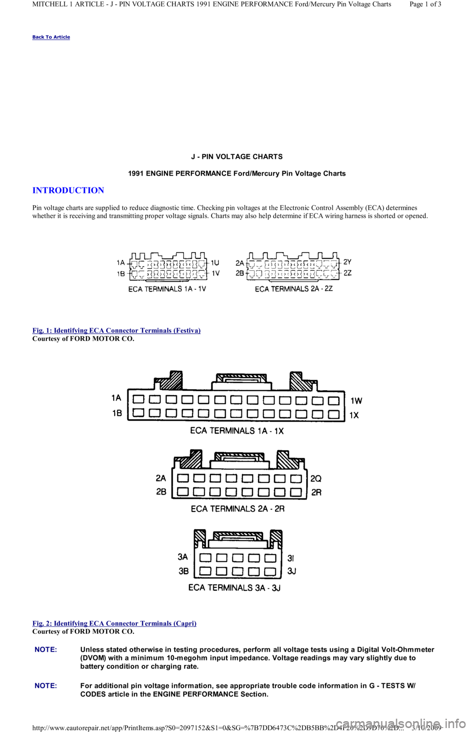
Pin voltage charts are supplied to reduce diagnostic time. Checking pin voltages at the Electronic Control Assembly (ECA) determin es
whether it is receiving and transmitting proper voltage signals. Charts may also help determine if ECA wiring harness is shorted or opened.
Fig. 1: Identifying ECA Connector Terminals (Festiva)
Courtesy of FORD MOTOR CO.
Fig. 2: Identifying ECA Connector Terminals (Capri)
Courtesy of FORD MOTOR CO.
NOTE:Unless stated otherwise in testing procedures, perform all voltage tests using a Digital Volt-Ohm m eter
(DVOM) with a m inim um 10-m egohm input im pedance. Voltage readings m ay vary slightly due to
battery condition or charging rate.
NOTE:For additional pin voltage inform ation, see appropriate trouble code inform ation in G - T EST S W/
CODES article in the ENGINE PERFORMANCE Section.
Page 1 of 3 MITCHELL 1 ARTICLE - J - PIN VOLTAGE CHARTS 1991 ENGINE PERFORMANCE Ford/Mercury Pin Voltage Charts
3/10/2009 http://www.eautorepair.net/app/PrintItems.asp?S0=2097152&S1=0&SG=%7B7DD6473C%2DB5BB%2D4F20%2D9D70%2D
...
Page 145 of 454
Back To Article
N - REMOVE/INST ALL/OVERHAUL
1991 ENGINE PERFORMANCE Ford/Mercury Rem oval, Overhaul & Installation
INTRODUCTION
Removal, overhaul and installation procedures are covered in this article. If component removal and installation is primarily an unbolt and
bolt-on procedure, only a torque specification may be furnished.
IGNITION SYSTEM
DISTRIBUTOR
Removal
Disconnect negative battery cable. On Capri, disconnect vacuum hose from vacuum control unit. Disconnect coil wire from distributor cap.
Remove screws and distributor cap. Disconnect electrical connectors. Mark position of distributor housing to cylinder head for reassembly.
Remove distributor mounting bolts and distributor.
Installation
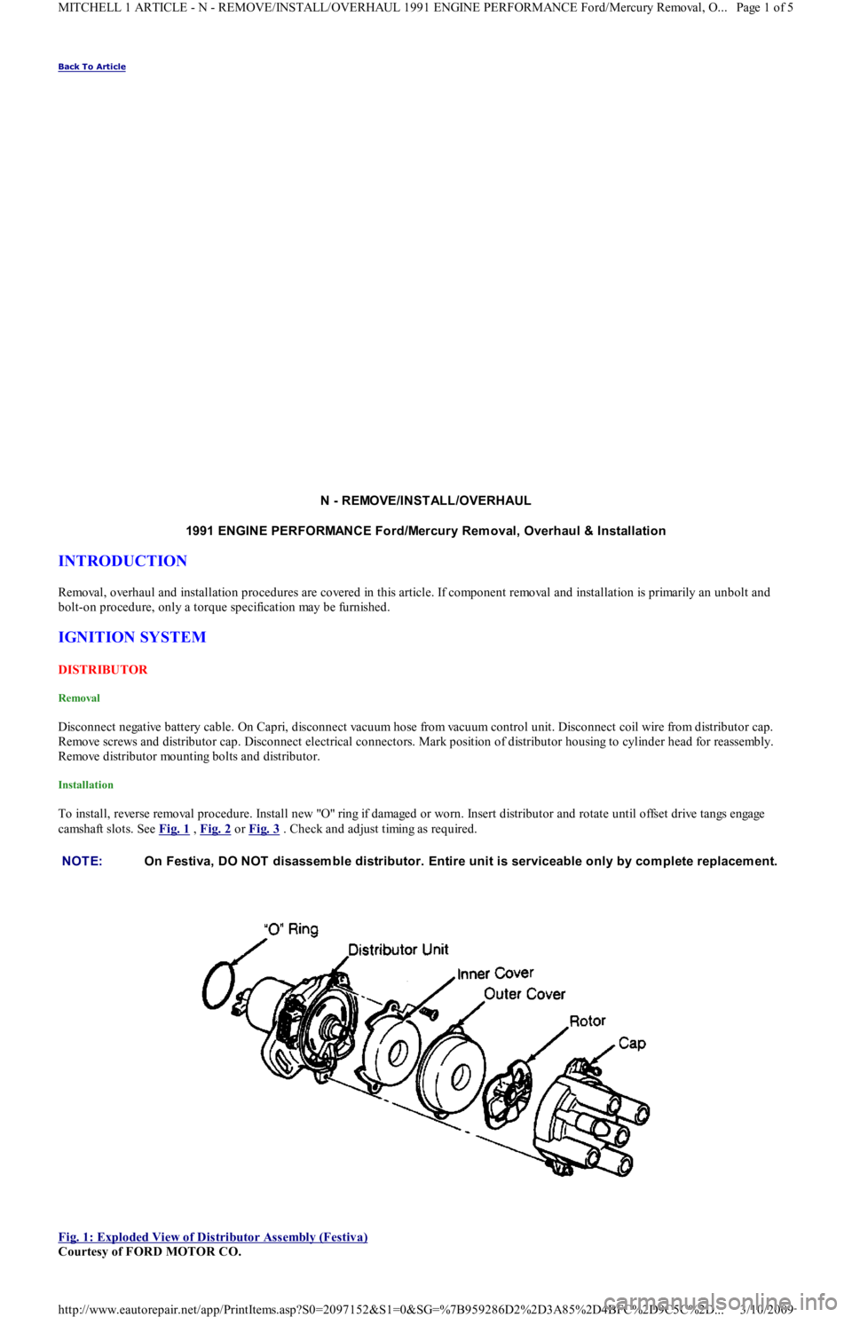
To install, reverse removal procedure. Install new "O" ring if damaged or worn. Insert distributor and rotate until offset drive tangs engage
camshaft slots. See Fig. 1
, Fig. 2 or Fig. 3 . Check and adjust timing as required.
Fig. 1: Exploded View of Distributor Assembly (Festiva)
Courtesy of FORD MOTOR CO. NOTE:On Festiva, DO NOT disassem ble distributor. Entire unit is serviceable only by com plete replacem ent.
Page 1 of 5 MITCHELL 1 ARTICLE - N - REMOVE/INSTALL/OVERHAUL 1991 ENGINE PERFORMANCE Ford/Mercury Removal, O
...
3/10/2009 http://www.eautorepair.net/app/PrintItems.asp?S0=2097152&S1=0&SG=%7B959286D2%2D3A85%2D4BFC%2D9C5C%2D
...
Page 147 of 454
ELECTRONIC CONTROL ASSEMBLY (ECA)
REMOVAL & INSTALLATION
Disconnect negative battery cable. On Festiva, from under instrument panel, remove heater duct. On Capri, disengage push-pin retainers by
pulling back on front edges of both center carpet panels. Remove carpet panel retaining screws and panels. Disconnect ECA wire harness
connector. Remove ECA bolts and ECA. To install, reverse removal procedure. On Festiva, ensure mounting clip is inserted into bulkhead
recess.
FUEL SYSTEM
FUEL SYSTEM PRESSURE RELEASE
Remove rear seat assembly. With engine running, disconnect fuel pump connector. Run engine until it stalls to relieve fuel line pressure.
FUEL INJECTORS
Removal
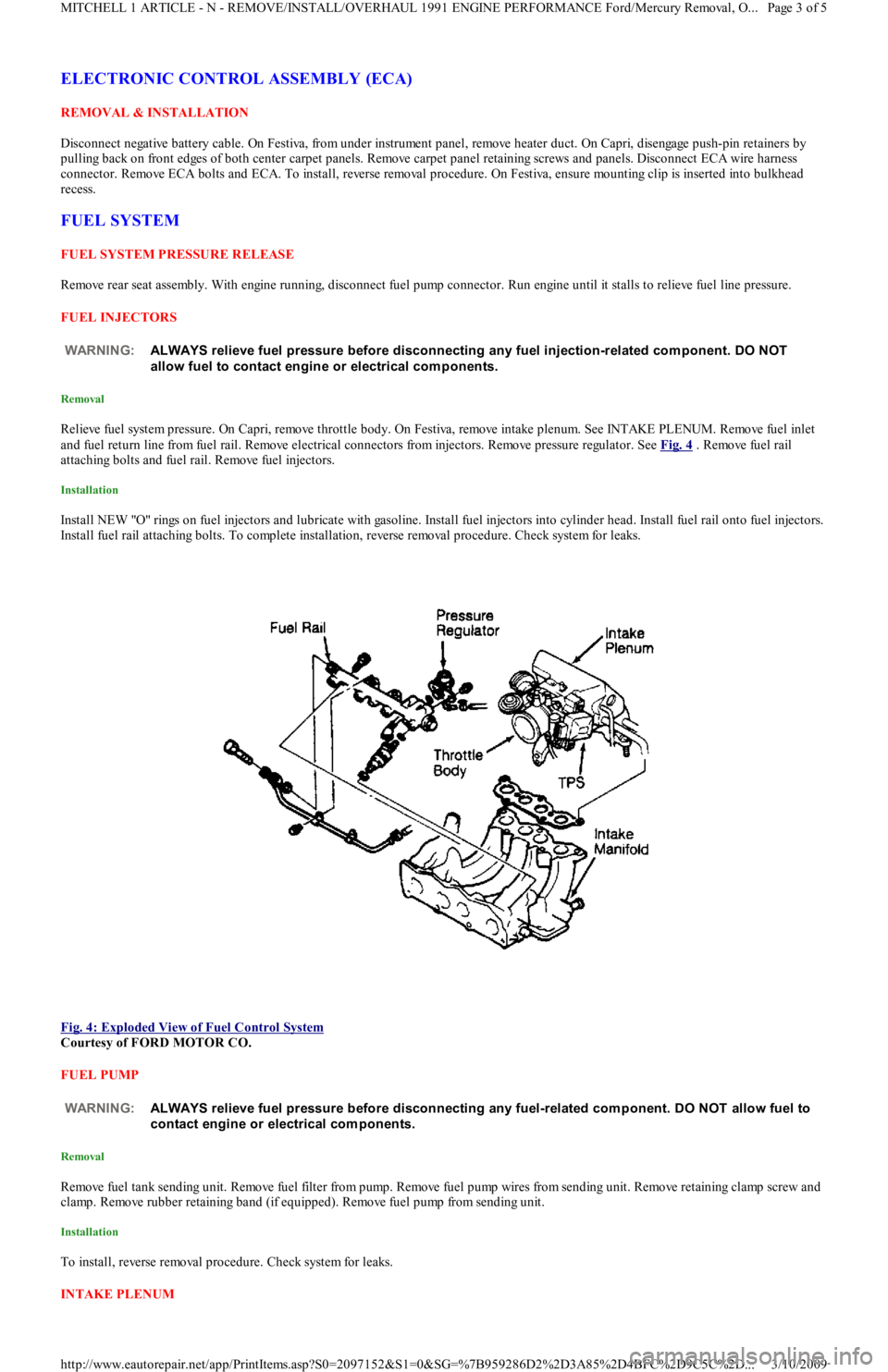
Relieve fuel system pressure. On Capri, remove throttle body. On Festiva, remove intake plenum. See INTAKE PLENUM. Remove fuel inlet
and fuel return line from fuel rail. Remove electrical connectors from injectors. Remove pressure regulator. See Fig. 4
. Remove fuel rail
attaching bolts and fuel rail. Remove fuel injectors.
Installation
Install NEW "O" rings on fuel injectors and lubricate with gasoline. Install fuel injectors into cylinder head. Install fuel rail onto fuel injectors.
Install fuel rail attaching bolts. To complete installation, reverse removal procedure. Check system for leaks.
Fig. 4: Exploded View of Fuel Control System
Courtesy of FORD MOTOR CO.
FUEL PUMP
Removal
Remove fuel tank sending unit. Remove fuel filter from pump. Remove fuel pump wires from sending unit. Remove retaining clamp screw and
clamp. Remove rubber retaining band (if equipped). Remove fuel pump from sending unit.
Installation
To install, reverse removal procedure. Check system for leaks.
INTAKE PLENUM WARNING:ALWAYS relieve fuel pressure before disconnecting any fuel injection-related com ponent. DO NOT
allow fuel to contact engine or electrical com ponents.
WARNING:ALWAYS relieve fuel pressure before disconnecting any fuel-related com ponent. DO NOT allow fuel to
contact engine or electrical com ponents.
Page 3 of 5 MITCHELL 1 ARTICLE - N - REMOVE/INSTALL/OVERHAUL 1991 ENGINE PERFORMANCE Ford/Mercury Removal, O
...
3/10/2009 http://www.eautorepair.net/app/PrintItems.asp?S0=2097152&S1=0&SG=%7B959286D2%2D3A85%2D4BFC%2D9C5C%2D
...
Page 148 of 454

Removal
Drain radiator and remove negative battery cable. Disconnect throttle cable. Remove air duct from throttle body. Disconnect throttle position
sensor/switch connector. Mark all coolant and vacuum hoses for reassembly reference and remove from throttle body. See Fig. 4
. Remove
intake plenum bolts and remove intake plenum and gasket.
Installation
To install, reverse removal procedure. Use NEW intake plenum-to-intake manifold gasket. Tighten bolts to specification, see TORQUE
SPECIFICATIONS at end of article.
OXYGEN (O2) SENSOR
Removal & Installation
Disconnect negative battery cable. Disconnect wire harness connector, and remove oxygen sensor. If exhaust sensor is difficult to remove, use
rust penetrant to avoid possible damage to exhaust threads. If new sensor is not pre-coated with anti-seize, apply anti-seize compound to
sensor threads. DO NOT remove anti-seize from sensor. To install, tighten sensor and attach wire harness connector.
THROTTLE BODY
Removal & Installation
Drain radiator and remove negative battery cable. Remove resonance chamber. Disconnect throttle cable. Remove air duct. Mark all coolant
and vacuum hoses for reassembly reference and remove from throttle body. Disconnect throttle position sensor/switch connector. Remove
throttle body nuts and bolts. Remove throttle body and gasket. To install, reverse removal procedure using NEW throttle body-to-intake
plenum gasket.
THROTTLE POSITION SENSOR/SWITCH
Removal & Installation
Disconnect negative battery cable. Disconnect throttle position sensor/switch connector. Remove attaching bolts. Remove sensor/switch from
throttle body. To install, reverse removal procedure.
TURBOCHARGER
Removal
1. Drain radiator and remove negative battery cable. Remove throttle body air intake tube. Disconnect intercooler hose from turbocharger
assembly. Disconnect O2 sensor. Remove lower heat shield retaining bolts and lower heat shield from turbocharger. Remove upper heat
shield retaining bolts and upper heat shield from exhaust manifold.
2. Slide O2 sensor wire and guide through upper heat shield. Remove side heat shield retaining bolts from turbocharger, and remove sid e
heat shield. Remove power steering belt. Remove power steering pump through bolt and adjuster nuts and bolts. Disconnect lower
radiator hose from water pump.
3. Pull pump from bracket, and position pump to access mounting bracket retaining nut and bolts. Remove mounting bracket-to-engine nut
and bolts and remove bracket. Remove air cleaner duct retaining screws. Loosen clamp at turbocharger and move duct tube out of way.
Disconnect coolant supply hose at turbocharger.
4. Remove bolt and sealing washers attaching oil supply line at engine block. Raise vehicle on hoist. Remove nuts and washers from
exhaust pipe flange. Remove bolts attaching exhaust hanger to engine block. Slide rubber exhaust hangers from catalytic converter. Pull
exhaust pipe downward and to left side of vehicle. Disconnect oil return hose from turbocharger. Disconnect coolant return hose fro m
turbocharger.
5. Remove turbocharger support bracket retaining bolts. Remove coolant by-pass tube outlet-to-water pump bolts. Lower vehicle. Loosen
retaining clamp bolt on coolant by-pass tube at rear of cylinder head. Remove 11 retaining nuts from exhaust manifold. Position coolant
by-pass tube out of way after pulling bracket from exhaust stud.
6. Remove exhaust manifold by pulling off studs and moving assembly towards right side of engine compartment, clearing cooling fan.
With assembly removed from vehicle, remove turbocharger-to-exhaust manifold nuts. Separate assembly and discard gasket.
Installation
1. Install NEW gasket on exhaust manifold and install turbocharger onto studs. Install turbocharger-to-exhaust manifold nuts. Remo ve o il
supply line from turbocharger. Install NEW exhaust gasket on cylinder head. Install turbocharger and exhaust manifold assembly onto
studs. Install coolant by-pass tube bracket onto exhaust stud. Install 11 retaining nuts onto exhaust manifold.
2. Securely tighten heater tube clamp bolt. Raise vehicle. Install coolant by-pass tube outlet-to-water pump bolts. Install turbocharger
support bracket retaining bolts. Connect coolant return hose to turbocharger. Connect oil return hose to turbocharger. Install exhaust
pipe onto turbocharger, and hand tighten nuts and washers. Install bolts attaching exhaust hanger to engine block.
3. Slide rubber exhaust hangers onto catalytic converter. Tighten exhaust pipe nuts and washers. Lower vehicle. Install bolt and sealing
washers attaching oil supply line at engine block. Install oil supply line onto turbocharger. To complete installation, reverse removal
procedure. Tighten bolts and nuts to specification, see TORQUE SPECIFICATIONS
at end of article. NOTE:T o prevent dust and dirt from entering intake m anifold ports, cover ports with clean cloth after
rem oving intake plenum .
WARNING:DO NOT rem ove oxygen sensor when engine is hot.
NOTE:Clean throttle body exterior before rem oval.
CAUT ION: Before installing turbocharger, put .8 oz. (25 m l) engine oil into turbocharger oil inlet.
Page 4 of 5 MITCHELL 1 ARTICLE - N - REMOVE/INSTALL/OVERHAUL 1991 ENGINE PERFORMANCE Ford/Mercury Removal, O
...
3/10/2009 http://www.eautorepair.net/app/PrintItems.asp?S0=2097152&S1=0&SG=%7B959286D2%2D3A85%2D4BFC%2D9C5C%2D
...
Page 149 of 454

VANE AIRFLOW (VAF) METER
Removal
1. Disconnect negative battery cable. On Capri, disconnect primary and secondary wires from coil. On Festiva, disconnect VAF wire
harness connector. Remove air duct.
2. On Capri, remove retaining bolt and ground wire from air cleaner cover. Remove air cleaner cover bolts and air cleaner cover. From
inside of air cleaner cover, remove VAF meter retaining nuts. On Festiva, remove attaching bolt and 4 nuts. Remove vane airflow met er.
Installation
To install, reverse removal procedure. Position new gasket over VAF mounting studs. Tighten bolts and nuts to specification, see TORQUE
SPECIFICATIONS at end of article.
TORQUE SPECIFICATIONS
TORQUE SPECIFICATIONS NOTE:For all on-vehicle adjustm ents not covered in this article, see ADJUST MENT S article in the ENGINE
PERFORMANCE Section.
ApplicationFt. Lbs. (N.m)
Coolant By-Pass Tube Outlet-To-Water Pump Bolts14-19 (19-26)
Distributor Mounting Bolts14-19 (19-26)
Exhaust Manifold Retaining Nuts29-42 (39-57)
Exhaust Pipe Nuts18-25 (24-34)
Fuel Line-To-Fuel Filter Bolt18-25 (24-34)
Fuel Pressure Regulator Nut(1)
Fuel Rail Retaining Bolt14-19 (19-26)
Heat Shield Bolts14-19 (19-26)
Intake Plenum Bolts/Nuts11-16 (15-22)
Oil Supply Line-To-Turbocharger Bolt12-17 (16-23)
Oxygen Sensor(1)
Power Steering Pump Bracket-To-Engine Bolts/Nut35-48 (47-65)
Throttle Body Bolt/Nuts12-17 (16-23)
Turbocharger Support Bracket Bolts32-45 (43-61)
Turbocharger-To-Exhaust Manifold Nuts20-25 (27-34)
INCH Lbs. (N.m)
Barometric Pressure (BP) Sensor Nut54-84 (6-9)
MAP Sensor Nuts54-84 (6-9)
Oil Supply Line-To-Engine Block Bolt104-156 (12-18)
Vane Airflow Meter Nuts110-152 (12-18)
(1)Information not available from manufacturer.
Copyr ight 2009 Mitchell Repair Information Company, LLC. All Rights Reserved.
Article GUID: A00022705
Page 5 of 5 MITCHELL 1 ARTICLE - N - REMOVE/INSTALL/OVERHAUL 1991 ENGINE PERFORMANCE Ford/Mercury Removal, O
...
3/10/2009 http://www.eautorepair.net/app/PrintItems.asp?S0=2097152&S1=0&SG=%7B959286D2%2D3A85%2D4BFC%2D9C5C%2D
...
Page 153 of 454
Back To Article
C - SPECIFICATIONS
1991 ENGINE PERFORMANCE Ford/Mercury - Service & Adjustm ent Specifications
INTRODUCTION
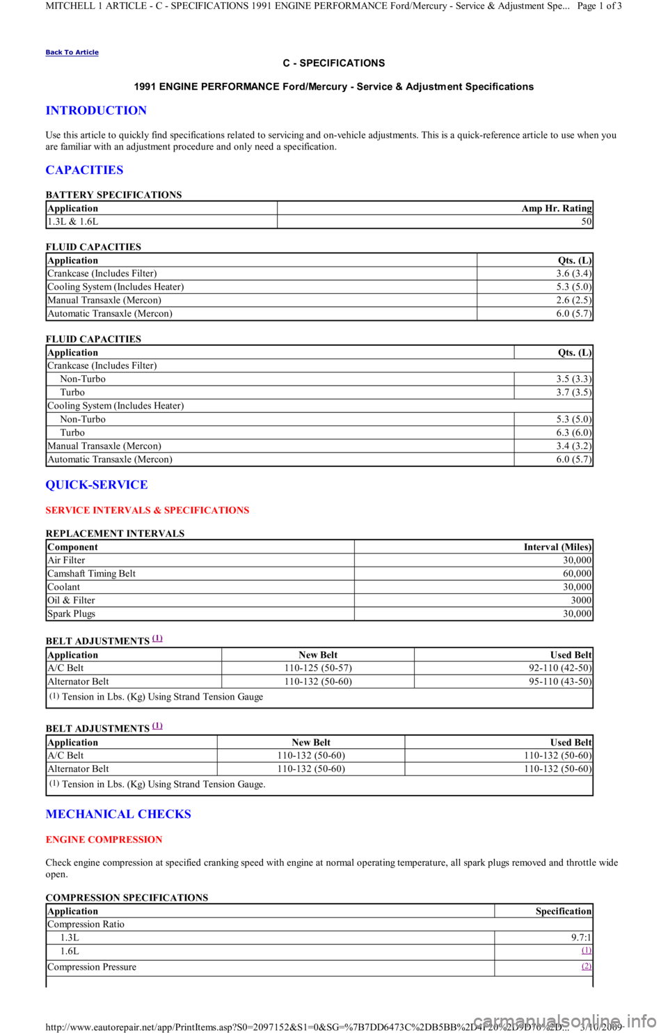
Use this article to quickly find specifications related to servicing and on-vehicle adjustments. This is a quick-reference article to use when you
are familiar with an adjustment procedure and only need a specification.
CAPACITIES
BATTERY SPECIFICATIONS
FLUID CAPACITIES
FLUID CAPACITIES
QUICK-SERVICE
SERVICE INTERVALS & SPECIFICATIONS
REPLACEMENT INTERVALS
BELT ADJUSTMENTS
(1)
BELT ADJUSTMENTS
(1)
MECHANICAL CHECKS
ENGINE COMPRESSION
Check engine compression at specified cranking speed with engine at normal operating temperature, all spark plugs removed and throttle wide
open.
COMPRESSION SPECIFICATIONS
ApplicationAmp Hr. Rating
1.3L & 1.6L50
ApplicationQts. (L)
Crankcase (Includes Filter)3.6 (3.4)
Cooling System (Includes Heater)5.3 (5.0)
Manual Transaxle (Mercon)2.6 (2.5)
Automatic Transaxle (Mercon)6.0 (5.7)
ApplicationQts. (L)
Crankcase (Includes Filter)
Non-Turbo3.5 (3.3)
Turbo3.7 (3.5)
Cooling System (Includes Heater)
Non-Turbo5.3 (5.0)
Turbo6.3 (6.0)
Manual Transaxle (Mercon)3.4 (3.2)
Automatic Transaxle (Mercon)6.0 (5.7)
ComponentInterval (Miles)
Air Filter30,000
Camsh aft Timin g Bel t60,000
Coolant30,000
Oil & Filter3000
Spark Plugs30,000
ApplicationNew BeltUsed Belt
A/C Belt110-125 (50-57)92-110 (42-50)
Alternator Belt110-132 (50-60)95-110 (43-50)
(1)Tension in Lbs. (Kg) Using Strand Tension Gauge
ApplicationNew BeltUsed Belt
A/C Belt110-132 (50-60)110-132 (50-60)
Alternator Belt110-132 (50-60)110-132 (50-60)
(1)Tension in Lbs. (Kg) Using Strand Tension Gauge.
ApplicationSpecification
Compression Ratio
1.3L9.7:1
1.6L(1)
Compression Pressure(2)
Page 1 of 3 MITCHELL 1 ARTICLE - C - SPECIFICATIONS 1991 ENGINE PERFORMANCE Ford/Mercury - Service & Adjustment Spe
...
3/10/2009 http://www.eautorepair.net/app/PrintItems.asp?S0=2097152&S1=0&SG=%7B7DD6473C%2DB5BB%2D4F20%2D9D70%2D
...
Page 158 of 454
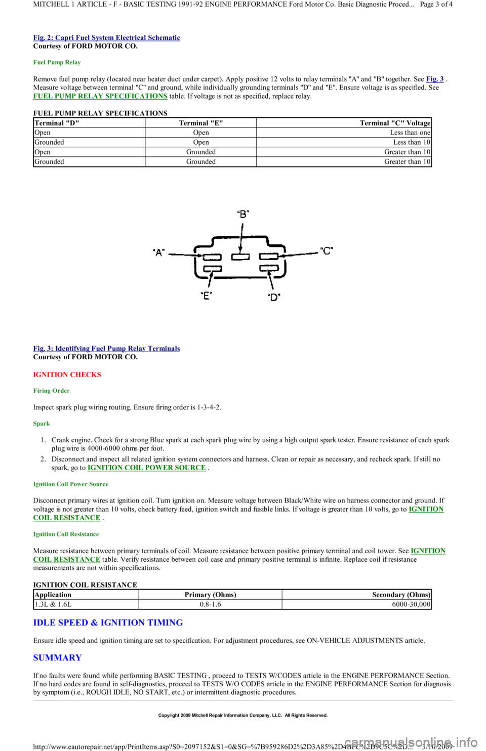
Fig. 2: Capri Fuel System Electrical Schematic
Courtesy of FORD MOTOR CO.
Fuel Pump Relay
Remove fuel pump relay (located near heater duct under carpet). Apply positive 12 volts to relay terminals "A" and "B" together. See Fig. 3 .
Measure voltage between terminal "C" and ground, while individually grounding terminals "D" and "E". Ensure voltage is as specified. See
FUEL PUMP RELAY SPECIFICATIONS
table. If voltage is not as specified, replace relay.
FUEL PUMP RELAY SPECIFICATIONS
Fig. 3: Identifying Fuel Pump Relay Terminals
Courtesy of FORD MOTOR CO.
IGNITION CHECKS
Firing Order
Inspect spark plug wiring routing. Ensure firing order is 1-3-4-2.
Spark
1. Crank engine. Check for a strong Blue spark at each spark plug wire by using a high output spark tester. Ensure resistance of each spark
plug wire is 4000-6000 ohms per foot.
2. Disconnect and inspect all related ignition system connectors and harness. Clean or repair as necessary, and recheck spark. If st il l n o
spark, go to IGNITION COIL POWER SOURCE
.
Ignition Coil Power Source
Disconnect primary wires at ignition coil. Turn ignition on. Measure voltage between Black/White wire on harness connector and ground. If
voltage is not greater than 10 volts, check battery feed, ignition switch and fusible links. If voltage is greater than 10 volts, go to IGNITION
COIL RESISTANCE .
Ignition Coil Resistance
Measure resistance between primary terminals of coil. Measure resistance between positive primary terminal and coil tower. See IGNITION
COIL RESISTANCE table. Verify resistance between coil case and primary positive terminal is infinite. Replace coil if resistance
measurements are not within specifications.
IGNITION COIL RESISTANCE
IDLE SPEED & IGNITION TIMING
Ensure idle speed and ignition timing are set to specification. For adjustment procedures, see ON-VEHICLE ADJUSTMENTS article.
SUMMARY
If no faults were found while performing BASIC TESTING , proceed to TESTS W/CODES article in the ENGINE PERFORMANCE Section.
If no hard codes are found in self-diagnostics, proceed to TESTS W/O CODES article in the ENGINE PERFORMANCE Section for diagnosis
by symptom (i.e., ROUGH IDLE, NO START, etc.) or intermittent diagnostic procedures.
Terminal "D"Terminal "E"Terminal "C" Voltage
OpenOpenLess than one
GroundedOpenLess than 10
OpenGroundedGreater than 10
GroundedGroundedGreater than 10
ApplicationPrimary (Ohms)Secondary (Ohms)
1.3L & 1.6L0.8-1.66000-30,000
Copyr ight 2009 Mitchell Repair Information Company, LLC. All Rights Reserved.
Page 3 of 4 MITCHELL 1 ARTICLE - F - BASIC TESTING 1991-92 ENGINE PERFORMANCE Ford Motor Co. Basic Diagnostic Proced
...
3/10/2009 http://www.eautorepair.net/app/PrintItems.asp?S0=2097152&S1=0&SG=%7B959286D2%2D3A85%2D4BFC%2D9C5C%2D
...
Page 161 of 454

Back To Article
I - SYST EM/COMPONENT T EST S
1991 ENGINE PERFORMANCE Ford Motor Co. - Ford/Mercury System & Com ponent T esting
INTRODUCTION
Before testing separate components or systems, perform procedures in BASIC TESTING article in the ENGINE PERFORMANCE Section.
Since many computer-controlled and monitored components set a trouble code if they malfunction, also perform procedures in TESTS
W/CODES article in the ENGINE PERFORMANCE Section.
AIR INDUCTION SYSTEMS
TURBOCHARGERS
Wastegate Actuator
Disconnect air hose from wastegate actuator. Apply 7.0-8.6 psi (.5-.6 kg/cm2 ) regulated air pressure to wastegate inlet fitting. Replace
turbocharger if wastegate actuator rod does not move.
COMPUTERIZED ENGINE CONTROLS
ELECTRONIC CONTROL ASSEMBLY (ECA)
Ground Circuits
Turn ignition off. Connect BOB, leaving ECA disconnected. Measure resistance between each specified BOB pin and ground. See ECA
GROUND CIRCUIT RESISTANCE table. Repair indicated ECA ground circuit if resistance is greater than 5 ohms.
ECA GROUND CIRCUIT RESISTANCE
Power Circuits
Turn ignition off. Connect BOB, leaving ECA disconnected. Turn ignition on. Repair indicated ECA power circuit if battery voltage d o e s n o t
appear on specified BOB pin. See ECA POWER CIRCUITS RESISTANCE
.
ECA POWER CIRCUIT RESISTANCE
ENGINE SENSORS & SWITCHES
Check each component and all related wiring for any looseness or damage. Make all resistance and voltage measurements using Breakout Box
(BOB) unless specified otherwise.
BAROMETRIC PRESSURE SENSOR (1.3L)
This unit is incorporated into the ECA, and cannot be checked or serviced separately. If a Code 14 is set and cannot be cleared, replace the
ECA.
BAROMETRIC PRESSURE (BP) SENSOR (1.6L) NOTE:T esting individual com ponents does not isolate shorts or opens. Perform all voltage tests with a Digital
Volt-Ohm m eter (DVOM) with a m inim um 10-m egohm input im pedance, unless stated otherwise in test
procedure. Use ohm m eter and Breakout Box (BOB) (007-00033) to isolate wiring harness shorts or
opens.
ECA PinBOB PinWire Color
1.3L
2A39,40,44Black
2B20Black
2C16Black
2D46,49Black
2J (2) (3) 6(3) White/Red
2J (4) 6Black
1.6L
2R49Black
3A (1) (1) 20Black
3G (1) (1) 40Black
(1)Turbo only.
(2)A/T models only.
(3)No continuity on A/T models.
(4)M/T models only.
ECA PinBOB PinWire Color
1.3L: 1A1White/Red
1.6L: 3J1Black/Red
Page 1 of 7 MITCHELL 1 ARTICLE - I - SYSTEM/COMPONENT TESTS 1991 ENGINE PERFORMANCE Ford Motor Co. - Ford/Merc
...
3/10/2009 http://www.eautorepair.net/app/PrintItems.asp?S0=2097152&S1=0&SG=%7B7DD6473C%2DB5BB%2D4F20%2D9D70%2D
...