1991 FORD FESTIVA battery
[x] Cancel search: batteryPage 345 of 454
Back To Article
HEAT ER SYST EM
1990-92 HEAT ER SYST EMS Ford Motor Co.
DESCRIPTION
The heater system consists of control panel, blower case, heater case, air control doors and ducts. The control panel incorporates 3 control
levers and a 3-speed fan switch. The control panel is located in the center of the instrument panel. All air control doors are cable operated
from the control panel.
The blower case is mounted on the bulkhead, behind the instrument panel on passenger's side of vehicle. The blower case houses a blower
motor, blower motor resistor and the fresh/recirculation air door. The heater case contains mode select door, temperature air mix door and
heater core.
OPERATION
Three control levers, temperature mix, fresh/recirculation and mode select, mechanically operate their associated cables and doors. The
temperature control lever adjusts the mix of fresh or recirculated air with heated air. In full heat position, all airflow goes through the heater
core.
In full cool position, the mix air door closes, allowing airflow to by-pass the heater core. The mode select lever, directs airflow to selected
vents. The fresh/recirculation control lever allows selection of fresh (outside) air or recirculated compartment air.
AJUSTMENT
FRESH/RECIRCULATION CONTROL CABLE
Remove the glove box. Remove fresh/recirculation cable retaining clip. Move control lever to RECIRCULATION position, while holding the
lever door in RECIRCULATION position. Ensure control lever does not move. Install fresh/recirculation cable retaining clip.
MODE SELECT CABLE
Remove mode select cable retaining clip. Move mode select lever to VENT position. Hold mode select lever downward against its stop.
Ensure that mode select lever does not move. Install mode select cable retaining clip.
TEMPERATURE CONTROL CABLE
Set temperature control lever to maximum cold position. Remove temperature cable retaining clip. Hold temperature control lever upward and
against its stop. Ensure that temperature lever does not move. Install temperature cable retaining clip.
TROUBLE SHOOTING
BLOWER MOTOR INOPERATIVE
Check blown motor fuse. Check for defective blower motor and/or blower motor resistor. Check blower motor switch. Check for open in
ground wire. Check for loose electrical connectors or poor connections. See WIRING DIAGRAMS
in this article.
BLOWER DOES NOT CHANGE SPEED
Check for defective blower motor. Check blower motor wiring harness. Check blower motor resistor. Check for blower motor fan switch. See
WIRING DIAGRAMS
in this article.
BLOWER RUNS CONSTANTLY
Check for defective blower motor resistor. Check for short in blower switch or wiring. See WIRING DIAGRAMS
in this article.
HEATER TEMPERATURE INSUFFICIENT
Check for proper coolant level. Check water pump for noise, leaks or wear. Check heater hoses for leaks or restrictions. Check heater core for
leaks, plugs or restrictions. Check inlet and outlet heater hoses for hot water flow. Check thermostat condition and operation. Check air mix
door position and adjust cable if necessary.
IMPROPER WARM AIR DISTRIBUTION
Check air mix door position. Adjust cable as necessary. Check function control door position. Adjust cable as necessary. Check for restriction
in ventilation air duct assembly. Repair as necessary.
TESTING BLOWER MOTOR & RESISTOR
1. Ensure 15-amp blower motor fuse is okay. Using voltmeter, check for battery voltage at blower motor Blue/Yellow terminal. If battery
voltage is present, go to next step. If battery voltage is not present, repair open in Blue/Yellow wire between blower motor and fuse box.
2. Disconnect blower motor connector. Using a jumper wire, apply battery voltage to Blue/Yellow terminal and ground the Blue/Red
terminal. If blower motor does not run, replace blower motor. If blower motor runs, go to next step.
3. Reconnect blower motor connector. Turn ignition on. Turn blower motor off. Disconnect the blower motor resistor connector. Using a
voltmeter, measure voltage at Blue/Red terminal of resistor connector. If battery voltage is not present, repair open in Blue/Red wire
between resistor and blower motor. If voltage is present, go to next step.
4. Using a jumper wire, ground Blue/Black, Blue/Yellow and Blue/White terminals of the blower fan switch one at a time. If the motor
runs at 3 different speeds, go to next step. If not, repair open in wire that failed to operate blower motor.
Page 1 of 4 MITCHELL 1 ARTICLE - HEATER SYSTEM 1990-92 HEATER SYSTEMS Ford Motor Co.
3/10/2009 http://www.eautorepair.net/app/PrintItems.asp?S0=2097152&S1=0&SG=%7B9B990D68%2D660A%2D45E9%2D8F46%2DE
...
Page 346 of 454
5. Check blower motor fan switch continuity. Resistance should not exceed 4 ohms. See BLOWER MOTOR FAN SWITCH
CONTINUITY table. If continuity is not present, replace fan switch. If continuity is okay, repair open in Black wire from blower motor
switch to ground.
BLOWER MOTOR FAN SWITCH CONTINUITY
REMOVAL & INSTALLATION
CONTROL PANEL
1. Remove bezel screws and accessory bezel. Remove radio. Remove 4 screws securing control panel to instrument panel. Remove glove
box attaching screws and glove box. Remove the retaining clip and disconnect fresh/recirculation air door cable from mode door lever.
2. Disconnect mode select cable at mode control door lever. Disconnect temperature control cable at temperature control mode door lever.
Pull control panel away from instrument panel. Disconnect blower motor switch connector. Disconnect illumination electrical
connector. Remove control panel. To install, reverse removal procedure. Adjust control cables. See ADJUSTMENTS in this article.
BLOWER MOTOR FAN SWITCH
Remove control panel. See CONTROL PANEL R & I
. Remove blower motor fan switch knob. Remove attaching nut. To install, reverse
removal procedure.
HEATER CORE
1. Disconnect negative battery cable. Remove steering wheel by prying out center trim insert and removing steering wheel retaining nut.
Remove 2 steering wheel cover retaining screws and remove cover. Using a steering wheel puller, remove steering wheel.
2. Remove 5 screws and remove lower and upper steering column covers. Disconnect electrical connections and remove multifunction
switch. Remove 5 screws and pull instrument cluster hood rearward. Disconnect electrical connections and remove instrument cluster
hood.
3. Disconnect speedometer cable at transaxle. Remove 4 instrument cluster screws. Pull instrument cluster rearward and disconnect
speedometer cable and electrical connections. Remove instrument cluster.
4. Remove 2 center bracket mounting bolts under steering column and remove bracket. Remove glove box attaching screws and remove
glove box. Remove left and right heater ducts. Remove fuse panel cover. Remove 2 screws securing fuse panel and push fuse panel
inward. DO NOT remove fuse panel.
5. Slide both seats to most forward position. Remove 2 console attaching screws, located in front of seat belt anchors. Slide both seats to
rearmost position. Remove parking brake console insert. Using a Phillips screwdriver, remove push retainer insert, located at front lower
edge of parking brake console. Pull back on parking brake lever and remove parking brake console.
6. Remove gearshift knob. Remove screws and remove shift console. Remove radio/heater control panel bezel screws and remove bezel.
Remove 4 radio attaching screws. Pull radio out and disconnect antenna lead and electrical connections. Disconnect radio ground lead
and remove radio.
7. Remove 4 screws attaching heater control panel. Disconnect control cables and electrical connections. Remove control panel, while
pulling cables through opening.
8. Pry out bolt cover trim inserts in top corners of dash. Remove bolts located under trim panels. Remove 7 instrument panel attaching
bolts and 2 nuts. Pull instrument panel rearward. Disconnect any harness connectors and clips. Remove instrument panel.
9. Disconnect electrical connections at blower and resistor. Remove harness from routing brackets on heater box. Loosen clamp screw
securing air inlet housing. Remove attaching nuts at top and bottom of heater box. Disconnect defroster ducts and remove heater
assembly.
10. Disconnect link connecting 2 defroster doors. Remove attaching screw just above and to right of blower resistor. Turn heater assembly
around and remove screw just to left of blower motor opening. Remove clips securing 2 halves of heater assembly. Separate halves. Lift
out heater core.
11. To install, reverse removal procedure. Ensure all heater control cables are routed and adjusted properly. See ADJUSTMENTS in this
article. Fill cooling system. Check for leaks.
BLOWER MOTOR & RESISTOR
Disconnect negative battery cable. Remove instrument panel spacer brace located below steering column. Remove airflow duct below steering
column. Disconnect blower motor or resistor wiring. Remove 3 blower motor attaching screws or 2 resistor attaching screws and remove
component. To install, reverse removal procedure.
Switch PositionContinuity Between Wire Colors
1Black-to-Blue/White
2Black-to-Blue/Yellow & Blue/Yellow-to-Blue/Red
3Black-to-Blue/Black & Blue/Black-to-Blue/Red
Page 2 of 4 MITCHELL 1 ARTICLE - HEATER SYSTEM 1990-92 HEATER SYSTEMS Ford Motor Co.
3/10/2009 http://www.eautorepair.net/app/PrintItems.asp?S0=2097152&S1=0&SG=%7B9B990D68%2D660A%2D45E9%2D8F46%2DE
...
Page 360 of 454
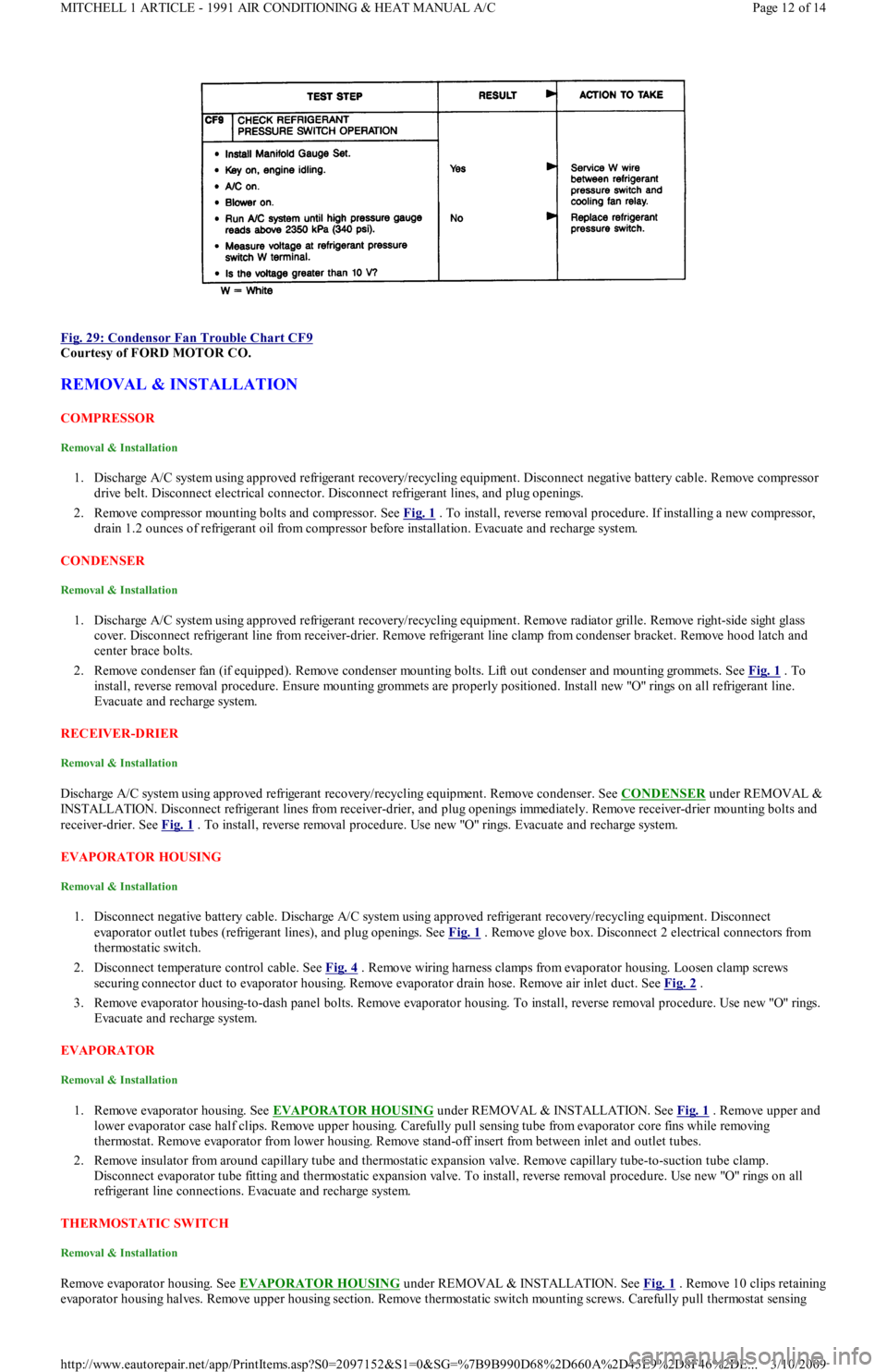
Fig. 29: Condensor Fan Trouble Chart CF9
Courtesy of FORD MOTOR CO.
REMOVAL & INSTALLATION
COMPRESSOR
Removal & Installation
1. Discharge A/C system using approved refrigerant recovery/recycling equipment. Disconnect negative battery cable. Remove compressor
drive belt. Disconnect electrical connector. Disconnect refrigerant lines, and plug openings.
2. Remove compressor mounting bolts and compressor. See Fig. 1
. To install, reverse removal procedure. If installing a new compressor,
drain 1.2 ounces of refrigerant oil from compressor before installation. Evacuate and recharge system.
CONDENSER
Removal & Installation
1. Discharge A/C system using approved refrigerant recovery/recycling equipment. Remove radiator grille. Remove right-side sight glass
cover. Disconnect refrigerant line from receiver-drier. Remove refrigerant line clamp from condenser bracket. Remove hood latch and
center brace bolts.
2. Remove condenser fan (if equipped). Remove condenser mounting bolts. Lift out condenser and mounting grommets. See Fig. 1
. To
install, reverse removal procedure. Ensure mounting grommets are properly positioned. Install new "O" rings on all refrigerant line.
Evacuate and recharge system.
RECEIVER-DRIER
Removal & Installation
Discharge A/C system using approved refrigerant recovery/recycling equipment. Remove condenser. See CONDENSER under REMOVAL &
INSTALLATION. Disconnect refrigerant lines from receiver-drier, and plug openings immediately. Remove receiver-drier mounting bolts and
receiver-drier. See Fig. 1
. To install, reverse removal procedure. Use new "O" rings. Evacuate and recharge system.
EVAPORATOR HOUSING
Removal & Installation
1. Disconnect negative battery cable. Discharge A/C system using approved refrigerant recovery/recycling equipment. Disconnect
evaporator outlet tubes (refrigerant lines), and plug openings. See Fig. 1
. Remove glove box. Disconnect 2 electrical connectors from
thermostatic switch.
2. Disconnect temperature control cable. See Fig. 4
. Remove wiring harness clamps from evaporator housing. Loosen clamp screws
securing connector duct to evaporator housing. Remove evaporator drain hose. Remove air inlet duct. See Fig. 2
.
3. Remove evaporator housing-to-dash panel bolts. Remove evaporator housing. To install, reverse removal procedure. Use new "O" rings.
Evacuate and recharge system.
EVAPORATOR
Removal & Installation
1. Remove evaporator housing. See EVAPORATOR HOUSING under REMOVAL & INSTALLATION. See Fig. 1 . Remove upper and
lower evaporator case half clips. Remove upper housing. Carefully pull sensing tube from evaporator core fins while removing
thermostat. Remove evaporator from lower housing. Remove stand-off insert from between inlet and outlet tubes.
2. Remove insulator from around capillary tube and thermostatic expansion valve. Remove capillary tube-to-suction tube clamp.
Disconnect evaporator tube fitting and thermostatic expansion valve. To install, reverse removal procedure. Use new "O" rings on all
refrigerant line connections. Evacuate and recharge system.
THERMOSTATIC SW ITCH
Removal & Installation
Remove evaporator housing. See EVAPORATOR HOUSING under REMOVAL & INSTALLATION. See Fig. 1. Remove 10 clips retaining
evaporator housing halves. Remove upper housing section. Remove thermostatic switch mounting screws. Carefully pull thermostat sensing
Page 12 of 14 MITCHELL 1 ARTICLE - 1991 AIR CONDITIONING & HEAT MANUAL A/C
3/10/2009 http://www.eautorepair.net/app/PrintItems.asp?S0=2097152&S1=0&SG=%7B9B990D68%2D660A%2D45E9%2D8F46%2DE
...
Page 361 of 454
tube from evaporator core fins while removing thermostatic switch. To install, reverse removal procedure. Evacuate and recharge system.
THERMOSTATIC EXPANSION VALVE
Removal & Installation
1. Discharge A/C system using approved refrigerant recovery/recycling equipment. Remove evaporator housing. See EVAPORATOR
HOUSING under REMOVAL & INSTALLATION. Remove air inlet duct. See Fig. 1 .
2. Remove insulation from sensing bulb. Disconnect thermostatic expansion valve at evaporator tube fitting and inlet tube fitting (from
receiver-drier). See Fig. 3
. Remove thermostatic expansion valve. To install, reverse removal procedure. Use new "O" rings. Evacuate
and recharge system.
A/C RELAYS
Removal & Installation
A/C relays are located in left front corner of engine compartment, near battery. Unclip relay holder from its mounting bracket. Disconnect
relay wiring. DO NOT pull on wiring connector to remove relay from holder. Remove relay from holder. To install, reverse removal procedure.
A/C-HEATER CONTROL ASSEMBLY
Removal & Installation
1. A/C control module is located above radio. Remove accessory bezel. Remove radio (if necessary) and glove box. Disconnect
recirculated/fresh air cable from door lever. See Fig. 5
. Disconnect mode select cable from door lever. See Fig. 6 .
2. Disconnect temperature control cable from door lever. See Fig. 4
. Pull control assembly away from dash, and disconnect wiring
connectors. Remove control assembly.
3. To install, reverse removal procedure. Check and adjust temperature control, recirculated/fresh air and mode cables. See
ADJUSTMENTS. Test control assembly operation.
BLOWER MOTOR
Removal & Installation
Disconnect negative battery cable. Remove A/C air outlet duct located below steering column. See Fig. 2 . Disconnect blower motor wiring.
Remove blower motor attaching screws and blower motor. Remove blower wheel attaching nut. Remove blower wheel and washer. To install,
reverse removal procedure.
BLOWER MOTOR RESISTOR
Removal & Installation
Disconnect negative battery cable. Remove air duct located below steering column. See Fig. 2 . Disconnect blower motor resistor wiring.
Remove blower resistor attaching screws and resistor. To install, reverse removal procedure.
AIR DISTRIBUTION PLENUM
Removal & Installation
1. Remove instrument panel. See INSTRUMENT PANEL under REMOVAL & INSTALLATION. Drain cooling system. Disconnect
heater hoses in engine compartment. Disconnect wiring for blower motor and blower resistor. Disengage wiring harness and antenna
lead from bracket on front of air distribution housing.
2. Loosen connector duct-to-air inlet clamp screw. Remove upper and lower mounting nuts from plenum. Disengage and remove plenum
from defroster ducts. To install, reverse removal procedure. Refill cooling system, and check for leaks.
HEATER CORE
Removal & Installation
1. Remove air distribution plenum. See AIR DISTRIBUTION PLENUM under REMOVAL & INSTALLATION. Disconnect linkage
connecting defroster doors. Remove attaching screw located near blower resistor. Turn housing around and remove attaching screw
located near blower motor opening.
2. Remove clips retaining blower housing halves. Separate blower housing halves. Remove heater core. Remove tube insert from heater
core. To install, reverse removal procedure. Test system for proper operation.
INSTRUMENT PANEL
Removal & Installation
1. Disconnect negative battery cable. Remove steering wheel, steering column covers and multifunction switch assembly. Disconnect
electrical connectors from switches on instrument panel. Remove instrument cluster hood.
2. Disconnect speedometer cable from transmission. Remove 4 instrument cluster screws. Pull instrument cluster out from instrument
panel cluster enough to disconnect wiring and speedometer cable. Remove instrument cluster.
3. Remove steering column shield. Remove shield bracket. Remove glove box. Remove fuse panel cover and 4 fuse panel screws. Pull fu se
panel out, but DO NOT remove. Remove shift lever console and mount brackets. CAUTION: DO NOT rem ove screw in front of blower resistor, or blower resistor m ounting plate will fall into air
distribution plenum . T o retrieve plate, disassem ble instrum ent panel.
Page 13 of 14 MITCHELL 1 ARTICLE - 1991 AIR CONDITIONING & HEAT MANUAL A/C
3/10/2009 http://www.eautorepair.net/app/PrintItems.asp?S0=2097152&S1=0&SG=%7B9B990D68%2D660A%2D45E9%2D8F46%2DE
...
Page 365 of 454
Back To Article
MAINTENANCE INFORMATION
1988-93 MAINT ENANCE Ford Motor Co. Maintenance Inform ation
MODEL IDENTIFICATION
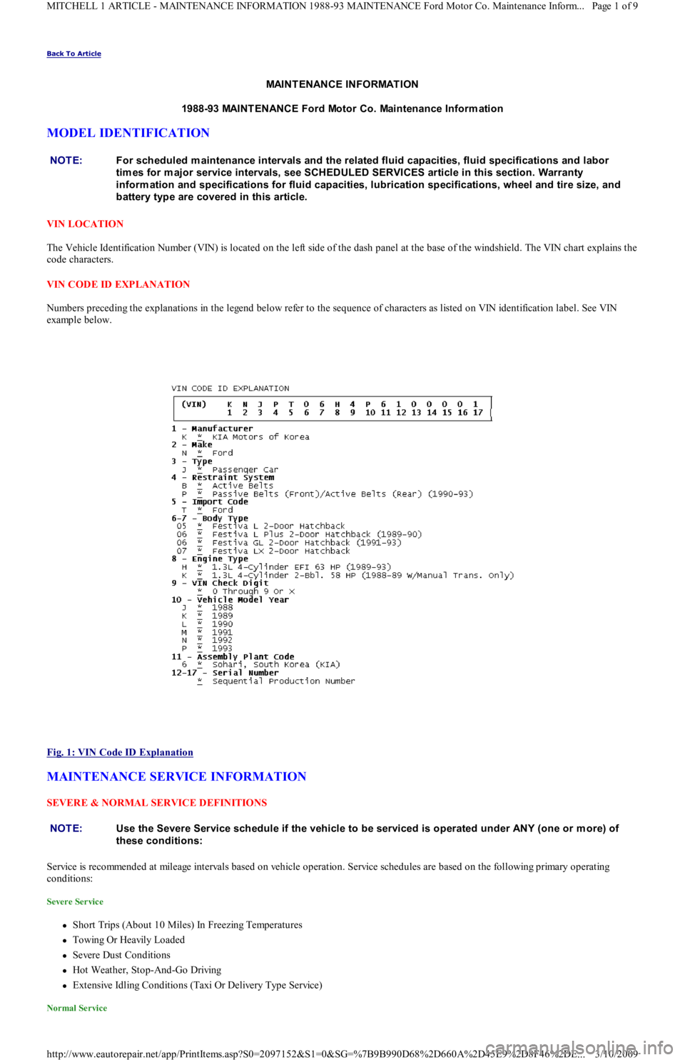
VIN LOCATION
The Vehicle Identification Number (VIN) is located on the left side of the dash panel at the base of the windshield. The VIN chart explains the
code characters.
VIN CODE ID EXPLANATION
Numbers preceding the explanations in the legend below refer to the sequence of characters as listed on VIN identification label. See VIN
example below.
Fig. 1: VIN Code ID Explanation
MAINTENANCE SERVICE INFORMATION
SEVERE & NORMAL SERVICE DEFINITIONS
Service is recommended at mileage intervals based on vehicle operation. Service schedules are based on the following primary operating
conditions:
Severe Service
Short Trips (About 10 Miles) In Freezing Temperatures
Towing Or Heavily Loaded
Severe Dust Conditions
Hot Weather, Stop-And-Go Driving
Extensive Idling Conditions (Taxi Or Delivery Type Service)
Normal Service
NOTE:For scheduled m aintenance intervals and the related fluid capacities, fluid specifications and labor
tim es for m ajor service intervals, see SCHEDULED SERVICES article in this section. Warranty
inform ation and specifications for fluid capacities, lubrication specifications, wheel and tire size, and
battery type are covered in this article.
NOTE:Use the Severe Service schedule if the vehicle to be serviced is operated under ANY (one or m ore) of
these conditions:
Page 1 of 9 MITCHELL 1 ARTICLE - MAINTENANCE INFORMATION 1988-93 MAINTENANCE Ford Motor Co. Maintenance Inform...
3/10/2009 http://www.eautorepair.net/app/PrintItems.asp?S0=2097152&S1=0&SG=%7B9B990D68%2D660A%2D45E9%2D8F46%2DE
...
Page 369 of 454
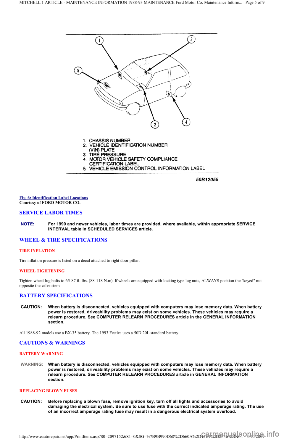
Fig. 6: Identification Label Locations
Courtesy of FORD MOTOR CO.
SERVICE LABOR TIMES
WHEEL & TIRE SPECIFICATIONS
TIRE INFLATION
Tire inflation pressure is listed on a decal attached to right door pillar.
WHEEL TIGHTENING
Tighten wheel lug bolts to 65-87 ft. lbs. (88-118 N.m). If wheels are equipped with locking type lug nuts, ALWAYS position the "keyed" nut
opposite the valve stem.
BATTERY SPECIFICATIONS
All 1988-92 models use a BX-35 battery. The 1993 Festiva uses a 50D 20L standard battery.
CAUTIONS & WARNINGS
BATTERY WARNING
REPLACING BLOWN FUSES
NOTE:For 1990 and newer vehicles, labor tim es are provided, where available, within appropriate SERVICE
INT ERVAL table in SCHEDULED SERVICES article.
CAUT ION: When battery is disconnected, vehicles equipped with com puters m ay lose m em ory data. When battery
power is restored, driveability problem s m ay exist on som e vehicles. T hese vehicles m ay require a
relearn procedure. See COMPUT ER RELEARN PROCEDURES article in the GENERAL INFORMAT ION
section.
WARNING:When battery is disconnected, vehicles equipped with com puters m ay lose m em ory data. When battery
power is restored, driveability problem s m ay exist on som e vehicles. T hese vehicles m ay require a
relearn procedure. See COMPUT ER RELEARN PROCEDURES article in GENERAL INFORMAT ION
section.
CAUT ION: Before replacing a blown fuse, rem ove ignition key, turn off all lights and accessories to avoid
dam aging the electrical system . Be sure to use fuse with the correct indicated am perage rating. T he use
of an incorrect am perage rating fuse m ay result in a dangerous electrical system overload.
Page 5 of 9 MITCHELL 1 ARTICLE - MAINTENANCE INFORMATION 1988-93 MAINTENANCE Ford Motor Co. Maintenance Inform...
3/10/2009 http://www.eautorepair.net/app/PrintItems.asp?S0=2097152&S1=0&SG=%7B9B990D68%2D660A%2D45E9%2D8F46%2DE
...
Page 371 of 454
whichever occurs first.
POWERTRAIN WARRANTY
Under this warranty, certain parts of the engine, transmission, axle and driveline are warranted against defects in materials and workmanship
for either 4 years/50,000 or 6 years/60,000 miles, depending on the model year. This coverage begins after 12 months or 12,000 miles. See
copy of warranty for specific components covered and length of coverage.
BUMPER-TO-BUMPER COVERAGE
All 1992-93 vehicles have complete warranty coverage against defects in materials and workmanship for 3 years or 36,000 miles, whichever
occurs first. There is no deductible with this warranty. Items not covered include tires and parts that are subject to normal wear and tear, such
as windshield wiper blades, brake linings, brake pads, clutch linings and scheduled maintenance items. There is no extended powertrain
coverage included in this warranty.
BATTERY COVERAGE
Begins at warranty start date and lasts up to 3 years or 36,000 miles, whichever occurs first. For the first 12 months in service (less than
36,000 miles), battery will be replaced at no charge. After that, battery will be replaced on a customer-participation basis: For the 13th-24th
month in service, Ford will pay 50%; for the 25th-36th month, Ford will pay 25%. Labor is covered for 3 years or 36,000 miles, whichever
occurs first.
SAFETY RESTRAINT SYSTEM COVERAGE
Begins at warranty start date and lasts for 5 years or 50,000 miles, whichever occurs first. Covers safety restraint problems not related to
comfort or appearance. Coverage for model years earlier than 1990 is 3 years with unlimited miles.
CORROSION COVERAGE
Begins at warranty start date and lasts for 6 years or 60,000 miles, whichever occurs first. 1992-93 models are covered for 6 years or 100,000
miles, whichever occurs first. Covers any holes in body sheet metal caused by corrosion.
EMISSIONS DEFECT & PERFORMANCE WARRANTIES (EXCEPT CALIFORNIA)
Defect Warranty ensures that vehicle meets applicable EPA regulations and that vehicle's emission control system is free from defects in
materials and workmanship for a period of 5 years or 50,000 miles, whichever occurs first.
The Performance Warranty covers all costs of repairing or adjusting any components or parts as needed for the vehicle to pass a Federally
required state or local emissions test.
Other emission control parts related to these components are covered by the Performance Warranty, where applicable. If another part fails due
to the failure of one of these components, both parts are covered. See customer's copy of warranty information for specific items co vered .
Performance Warranty coverage is limited to fewer components after 2 years or 24,000 miles.
EMISSIONS PERFORMANCE WARRANTY (CALIFORNIA)
If vehicle fails a Smog Check inspection, all necessary repairs and adjustments will be made by manufacturer to ensure that vehicle passes the
inspection. Warranty begins at warranty start date and lasts for a period of 3 years or 50,000 miles, whichever occurs first.
EMISSIONS DEFECT WARRANTY (CALIFORNIA)
If any emission-related part on the vehicle is defective, the part will be repaired or replaced by manufacturer. Warranty begins at warranty start
date and lasts for a period of 3 years or 50,000 miles, whichever occurs first.
Some emission-related parts are warranted for 7 years or 70,000 miles whichever occurs first, and will be repaired or replaced by manufacturer
if found to be defective in material or workmanship. See customer's copy of warranty information for specific items covered.
FUSES & FUSIBLE LINKS
FUSE PANEL & FUSIBLE LINK BLOCK LOCATIONS
The vehicle has a fuse block with fusible links and a fuse panel with circuit fuses. The fuse panel is located behind the instrument panel, left o
f
the steering column. The fuse block is located under the hood.
FUSE PANEL IDENTIFICATION NOTE:Powertrain Warranty varies in coverage length (4 years/50,000 m iles or 6 years/60,000 m iles) depending
on model year.
Page 7 of 9 MITCHELL 1 ARTICLE - MAINTENANCE INFORMATION 1988-93 MAINTENANCE Ford Motor Co. Maintenance Inform...
3/10/2009 http://www.eautorepair.net/app/PrintItems.asp?S0=2097152&S1=0&SG=%7B9B990D68%2D660A%2D45E9%2D8F46%2DE
...
Page 375 of 454
Back To Article
ST EERING SYST EM - MANUAL
1991 ST EERING Ford Motor Co. - Steering - Manual Rack & Pinion
DESCRIPTION
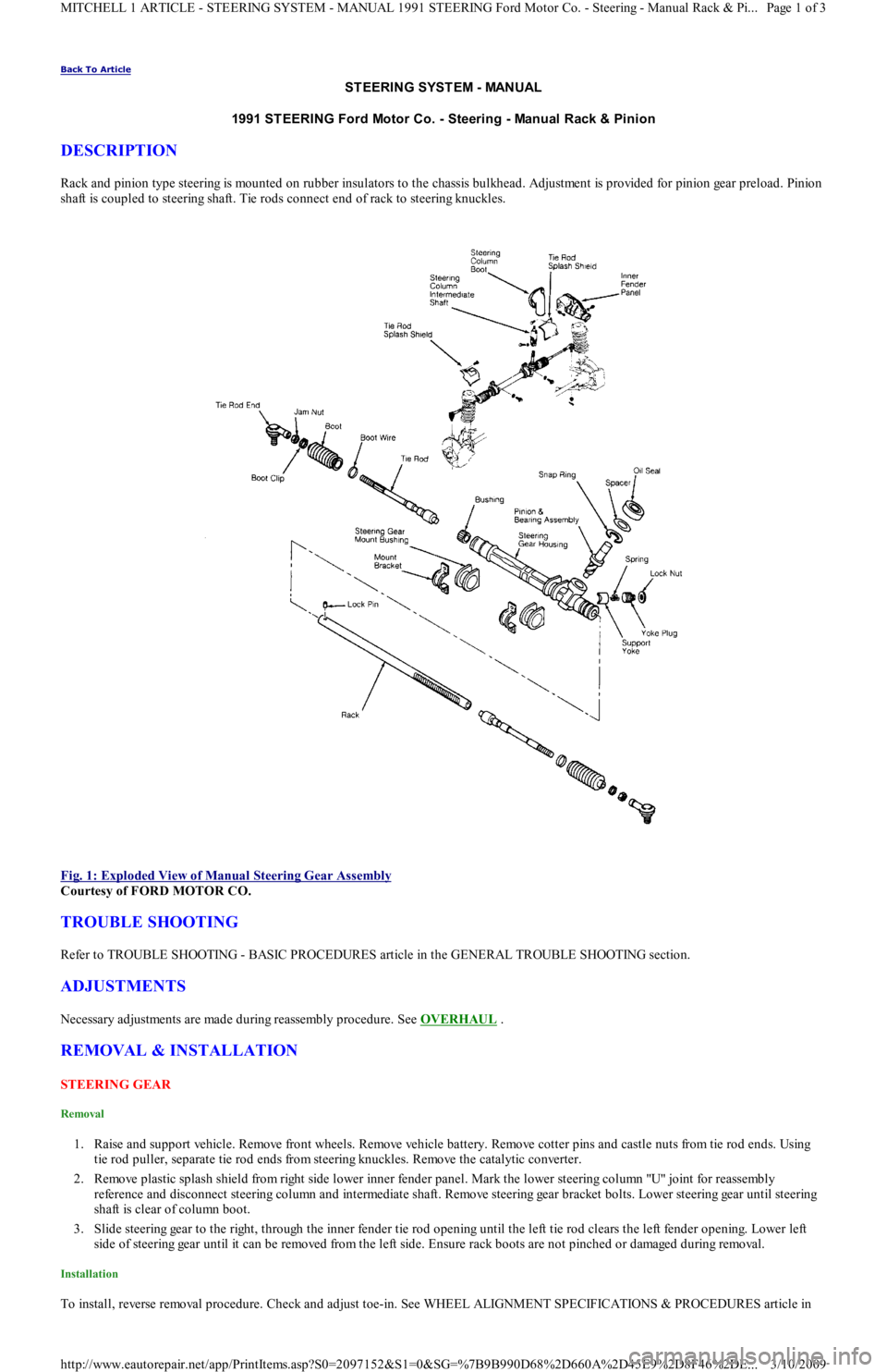
Rack and pinion type steering is mounted on rubber insulators to the chassis bulkhead. Adjustment is provided for pinion gear preload. Pinion
shaft is coupled to steering shaft. Tie rods connect end of rack to steering knuckles.
Fig. 1: Exploded View of Manual Steering Gear Assembly
Courtesy of FORD MOTOR CO.
TROUBLE SHOOTING
Refer to TROUBLE SHOOTING - BASIC PROCEDURES article in the GENERAL TROUBLE SHOOTING section.
ADJUSTMENTS
Necessary adjustments are made during reassembly procedure. See OVERHAUL .
REMOVAL & INSTALLATION
STEERING GEAR
Removal
1. Raise and support vehicle. Remove front wheels. Remove vehicle battery. Remove cotter pins and castle nuts from tie rod ends. Using
tie rod puller, separate tie rod ends from steering knuckles. Remove the catalytic converter.
2. Remove plastic splash shield from right side lower inner fender panel. Mark the lower steering column "U" joint for reassembly
reference and disconnect steering column and intermediate shaft. Remove steering gear bracket bolts. Lower steering gear until steering
shaft is clear of column boot.
3. Slide steering gear to the right, through the inner fender tie rod opening until the left tie rod clears the left fender opening. Lower left
side of steering gear until it can be removed from the left side. Ensure rack boots are not pinched or damaged during removal.
Installation
To install, reverse removal procedure. Check and adjust toe-in. See WHEEL ALIGNMENT SPECIFICATIONS & PROCEDURES article in
Page 1 of 3 MITCHELL 1 ARTICLE - STEERING SYSTEM - MANUAL 1991 STEERING Ford Motor Co. - Steering - Manual Rack & Pi
...
3/10/2009 http://www.eautorepair.net/app/PrintItems.asp?S0=2097152&S1=0&SG=%7B9B990D68%2D660A%2D45E9%2D8F46%2DE
...