1991 FORD FESTIVA battery
[x] Cancel search: batteryPage 378 of 454
Back To Article
ST EERING SYST EM - POWER
1991-92 ST EERING Ford Motor Co. - Steering - Power Rack & Pinion
DESCRIPTION & OPERATION
Power steering system consists of a rack and pinion steering gear, valve body, power steering pump, fluid reservoir and interconnecting
hydraulic lines. Pressure and return lines from pump are connected to valve body. A vane-type power steering pump draws fluid from the
steering reservoir. Fluid is compressed by rotor and vanes inside steering pump and sent to steering gear. Pressure is monitored and controlled
by a pressure switch and a control valve located inside of steering pump.
TROUBLE SHOOTING
Refer to TROUBLE SHOOTING - BASIC PROCEDURES article in the GENERAL TROUBLE SHOOTING section.
LUBRICATION
CAPACITY
Information is not available.
FLUID TYPE
Use Dexron-II ATF type fluid.
FLUID LEVEL CHECK
Check fluid level before engine is started, while fluid is still cool. Remove reservoir cap fluid indicator on steering pump. Check fluid level.
Fluid should be between the "L" and "H" marks on the level gauge dipstick. If fluid is needed, fill to the "L" mark on dipstick. Run engine until
warm and turn steering wheel fully in both directions about 10 times. Return steering to straight-ahead position and shut engine off. Ensure
fluid level is between "L" and "H" marks. Add fluid if necessary.
HYDRAULIC FLUID BLEEDING
1. Raise and support front of vehicle. Ensure pump reservoir is filled to specified level. With ignition coil wire disconnected, crank engine
and add fluid to steering pump until fluid level remains constant. While cranking engine, rotate steering from stop to stop. Recheck and
add fluid as necessary.
2. Start engine and allow to idle for several minutes. Turn steering wheel completely lock-to-lock several times. Check fluid level. Add
fluid as necessary. Continue this procedure until there is no bubbling or decrease in fluid level.
ADJUSTMENTS
BELT TENSION
On Festiva, remove air duct and air cleaner. On all models, loosen steering pump mounting pivot bolt and the adjusting bolt lock nut. Using
Belt Tension Gauge (021-0028A), fit gauge to longest available belt span for testing. Adjust belt to specification. See BELT TENSION
SPECIFICATIONS . Tighten adjuster lock nut to 32-45 ft. lbs. (43-61 N.m) on Capri or 27-38 ft. lbs. (37-52 N.m) on Festiva.
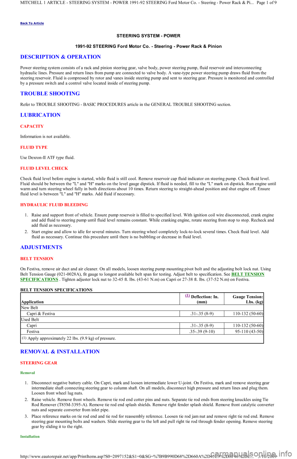
BELT TENSION SPECIFICATIONS
REMOVAL & INSTALLATION
STEERING GEAR
Removal
1. Disconnect negative battery cable. On Capri, mark and loosen intermediate lower U-joint. On Festiva, mark and remove steering gear
intermediate shaft connecting steering gear to column shaft. On all models, disconnect high pressure and return lines and plug them.
Loosen front wheel lug nuts.
2. Raise vehicle. Remove front wheels. Remove tie rod end cotter pins and nuts. Separate tie rod ends from steering knuckles using Tie
Rod Remover (T85M-3395-A). Remove tie rod end splash shields. Remove right fender splash shield. Remove front catalytic converter
nuts and separate converter from inlet pipe.
3. Place reference marks on tie rod end and tie rod for reassembly reference. Loosen tie rod jam nut and remove right tie rod end. Remove
steering gear mounting bolts and washers. Slide steering gear to the left and pull right tie rod through fender opening. Remove steering
gear by sliding it to the right.
Installation
Application
(1) Deflection: In.
(mm)Gauge Tension:
Lbs. (kg)
New Belt
Capri & Festiva.31-.35 (8-9)110-132 (50-60)
Used Belt
Capri.31-.35 (8-9)110-132 (50-60)
Festiva.35-.39 (9-10)95-110 (43-50)
(1)Apply approximately 22 lbs. (9.9 kg) of pressure.
Page 1 of 9 MITCHELL 1 ARTICLE - STEERING SYSTEM - POWER 1991-92 STEERING Ford Motor Co. - Steering - Power Rack & Pi
...
3/10/2009 http://www.eautorepair.net/app/PrintItems.asp?S0=2097152&S1=0&SG=%7B9B990D68%2D660A%2D45E9%2D8F46%2DE
...
Page 379 of 454
1. Position steering gear in its mounting position. Attach intermediate shaft to steering gear pinion and tighten clamp bolt to 13-20 ft. lbs.
(18-26 N.m). Guide intermediate shaft into steering column hole. Lower vehicle.
2. Lift steering gear and align intermediate shaft with universal joint and install clamp bolt. Raise vehicle. Install steering gear mounting
bolts and tighten to 23-34 ft. lbs. (31-46 N.m). Install right tie rod end, using marks made during removal for installation reference.
Attach tie rod ends to steering knuckles. Install tie rod end nuts and tighten to 22-33 ft. lbs. (29-44 N.m).
3. Install tie rod end cotter pins. Attach catalytic converter to inlet pipe and install attaching nuts. Tighten nuts to 23-34 ft. lbs. (31-46
N.m). Install tie rod end splash shields. Install right fender splash shield. install front wheels. Lower vehicle.
4. Connect high pressure and return lines. Connect negative battery cable. Add power steering fluid and bleed air from system and check
for leaks. See HYDRAULIC FLUID BLEEDING
under LUBRICATION.
POWER STEERING PUMP
Removal (Capri)
1. Remove right radiator support and brace. Remove pump drive belt. Disconnect intercooler outlet hose at throttle intake (if equipped).
R e mo ve gr o u n d wir e fr o m e n gin e l ift in g e ye .
2. Remove pressure and return hoses and plug. Remove wire from pressure switch. Remove adjusting screw, nut and block from pump
bracket. Remove pivot bolt. Remove bracket retaining bolts then remove pump.
Removal (Festiva)
Remove air duct and air cleaner. Disconnect electrical connector from fluid pressure switch on power steering pump. Disconnect and plug
return and pressure lines. Remove adjustment bolt. Remove lock nut, washer and bracket bolt. Loosen mounting bolt and disconnect drive
belt. Remove mounting bolt. Remove power steering pump.
Installation (Capri & Festiva)
To install pump, reverse removal procedure. Adjust steering belt tension. Tighten all nuts and bolts to specification. See TORQUE
SPECIFICATIONS . Add power steering fluid and bleed air from system and check for leaks. See HYDRAULIC FLUID BLEEDING
under LUBRICATION.
OVERHAUL
STEERING GEAR
Disassembly (Capri)
1. Remove steering gear and place in soft-jawed vise. Remove external hydraulic lines. See Fig. 1 . Remove mount brackets and rubber
mount bushings. Remove brass tubing seats using a self-tapping screw and 2 screwdrivers.
Page 2 of 9 MITCHELL 1 ARTICLE - STEERING SYSTEM - POWER 1991-92 STEERING Ford Motor Co. - Steering - Power Rack & Pi
...
3/10/2009 http://www.eautorepair.net/app/PrintItems.asp?S0=2097152&S1=0&SG=%7B9B990D68%2D660A%2D45E9%2D8F46%2DE
...
Page 387 of 454
Back To Article
ST EERING COLUMN
1991 ST EERING Ford Motor Co. - Steering Colum ns
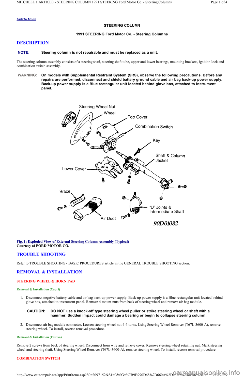
DESCRIPTION
The steering column assembly consists of a steering shaft, steering shaft tube, upper and lower bearings, mounting brackets, ignition lock and
combination switch assembly.
Fig. 1: Exploded View of External Steering Column Assembly (Typical)
Courtesy of FORD MOTOR CO.
TROUBLE SHOOTING
Refer to TROUBLE SHOOTING - BASIC PROCEDURES article in the GENERAL TROUBLE SHOOTING section.
REMOVAL & INSTALLATION
STEERING WHEEL & HORN PAD
Removal & Installation (Capri)
1. Disconnect negative battery cable and air bag back-up power supply. Back-up power supply is a Blue rectangular unit located behind
glove box, attached to instrument panel. Remove 4 mount nuts from back of steering wheel and remove air bag module.
2. Disconnect air bag module connector. Loosen steering wheel nut 4-6 turns. Using Steering Wheel Remover (T67L-3600-A), remove
steering wheel. To install, reverse removal procedure.
Removal & Installation (Festiva)
Remove 2 screws from back of steering wheel. Disconnect horn wire and remove cover. Remove steering wheel retaining nut. Mark steering
wheel and steering shaft. Using Steering Wheel Remover (T67L-3600-A), remove steering wheel. To install, reverse removal procedure.
COMBINATION SW ITCH NOTE:Steering colum n is not repairable and m ust be replaced as a unit.
WARNING:On m odels with Supplem ental Restraint System (SRS), observe the following precautions. Before any
repairs are perform ed, disconnect and shield battery ground cable and air bag back-up power supply.
Back-up power supply is a Blue rectangular unit located behind glove box, attached to instrum ent
panel.
CAUT ION: DO NOT use a knock-off type steering wheel puller or strike steering wheel or shaft with a
ham m er. Sudden im pact could dam age a bearing or begin to collapse steering colum n.
Page 1 of 4 MITCHELL 1 ARTICLE - STEERING COLUMN 1991 STEERING Ford Motor Co. - Steering Columns
3/10/2009 http://www.eautorepair.net/app/PrintItems.asp?S0=2097152&S1=0&SG=%7B9B990D68%2D660A%2D45E9%2D8F46%2DE
...
Page 388 of 454
Removal & Installation (Capri)
Disconnect negative battery cable. With steering wheel removed, remove screws from lower column cover and remove lower cover. Remove
steering column upper retaining bolts. Steering column will rest on instrument panel bracket. Release wiring harness clip and unplug
connectors. Remove 2 switch retaining screws and remove switch from steering column. To install, reverse removal procedure.
Removal & Installation (Festiva)
Disconnect negative battery cable. With steering wheel removed, remove screws from lower column cover and remove both upper and lower
cover. Release wiring harness clip and unplug connectors. Loosen band clamp securing switch hub to steering column jacket. Remove swit c h
from steering column. To install, reverse removal procedure.
IGNITION SWITCH & LOCK
Removal & Installation (Capri Ignition Switch)
1. Disconnect negative battery cable. With steering wheel removed, remove upper and lower column covers. Remove center access panel
and trim panel under steering wheel. Remove left side defroster connector tube.
2. Remove steering column upper attaching bolts. Lower steering column onto instrument panel brace. Remove ignition tumbler. With
ignition key inserted, rotate tumbler while pushing release pin with .125" (3.17 mm) drift. Pull tumbler out of ignition lock housing.
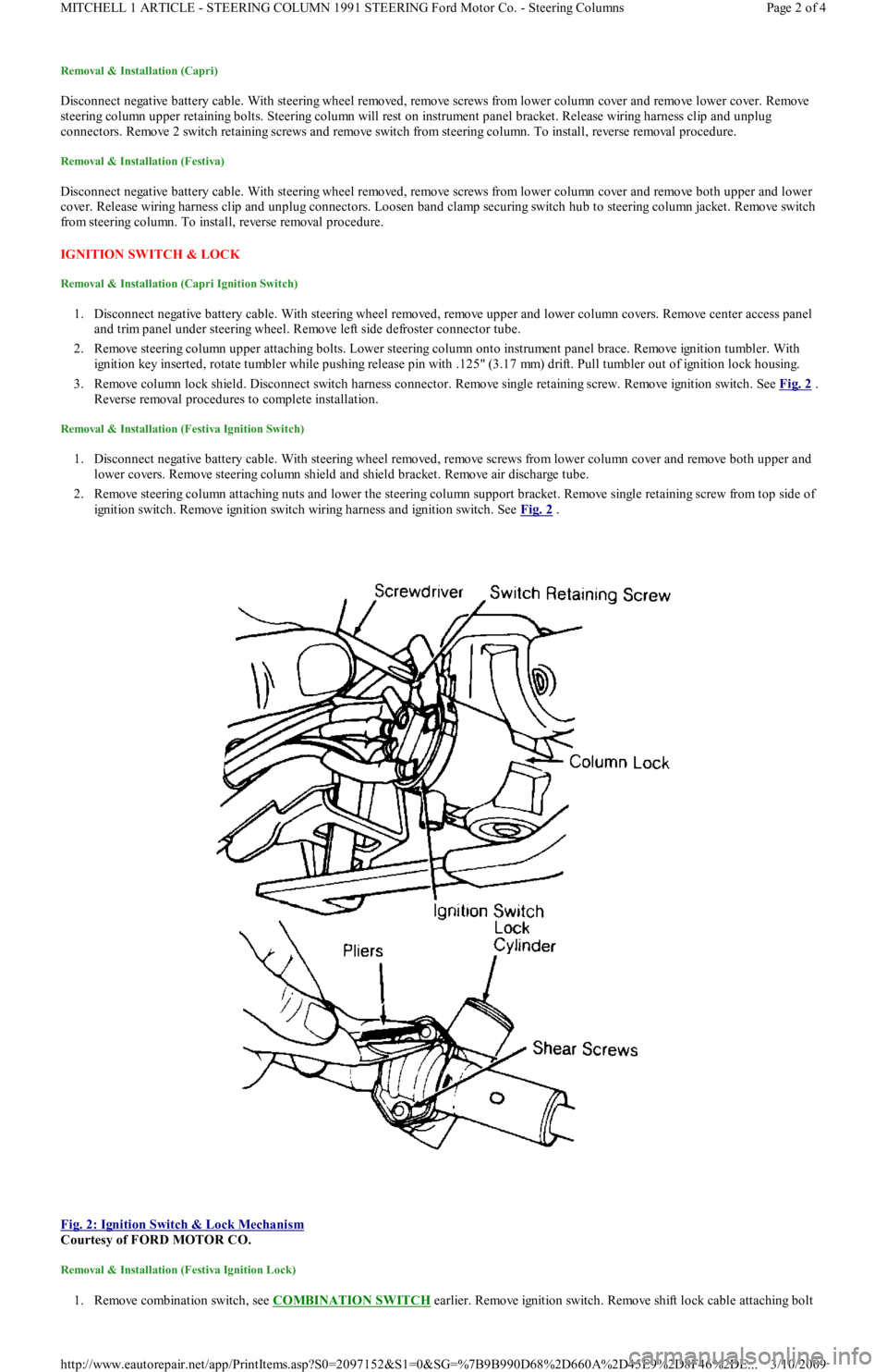
3. Remove column lock shield. Disconnect switch harness connector. Remove single retaining screw. Remove ignition switch. See Fig. 2
.
Reverse removal procedures to complete installation.
Removal & Installation (Festiva Ignition Switch)
1. Disconnect negative battery cable. With steering wheel removed, remove screws from lower column cover and remove both upper and
lower covers. Remove steering column shield and shield bracket. Remove air discharge tube.
2. Remove steering column attaching nuts and lower the steering column support bracket. Remove single retaining screw from top side of
ignition switch. Remove ignition switch wiring harness and ignition switch. See Fig. 2
.
Fig. 2: Ignition Switch & Lock Mechanism
Courtesy of FORD MOTOR CO.
Removal & Installation (Festiva Ignition Lock)
1. Remove combination switch, see COMBINATION SW ITCH earlier. Remove ignition switch. Remove shift lock cable attaching bolt
Page 2 of 4 MITCHELL 1 ARTICLE - STEERING COLUMN 1991 STEERING Ford Motor Co. - Steering Columns
3/10/2009 http://www.eautorepair.net/app/PrintItems.asp?S0=2097152&S1=0&SG=%7B9B990D68%2D660A%2D45E9%2D8F46%2DE
...
Page 389 of 454
and disconnect cable from lock housing. Using slim-nose locking pliers, grip and remove round headed shear screws securing column
lock housing and cap to column jacket. See Fig. 2
.
2. Remove lock housing. To install lock housing, position lock cylinder and cap on column jacket. Using new screws, tighten only enough
to hold lock housing in position. Use ignition key to ensure lock works correctly without binding. Adjust switch if necessary. Tighten
shear screws until heads break off. Install ignition switch in cylinder. Reverse removal procedures to complete installation.
STEERING COLUMN
Removal & Installation (Capri)
1. Place wheels in a straight-ahead position. Remove ignition key and lock steering wheel. Disconnect negative battery cable and air bag
back-up power supply. Back-up power supply is a Blue rectangular unit located behind glove box, attached to instrument panel.
2. Remove air bag module from steering wheel. Remove steering column access cover and trim panel. Remove defroster duct connecting
hose. Remove steering column lower shroud. Loosen lower steering c o l u mn r e t a in in g n u t s. R e mo ve st e e r in g c o l u mn u p p e r r e t a in in g
nuts.
3. Remove ignition lock shield and ignition switch mount screw. Disconnect all necessary electrical connectors. Mark and remove steering
shaft universal joint bolt. Remove steering column from instrument panel. To install, reverse removal procedure. Once steering column
is completely installed, check all switches and functions for proper operation.
Removal (Festiva)
1. Disconnect battery ground cable. Place wheels in a straight-ahead position. Remove steering wheel, upper and lower column covers,
combination switch, ignition switch and harness connectors.
2. Remove steering column shield and air duct from below steering column. Remove 2 steering column upper mounting bracket-to-
instrument panel crossmember nuts.
3. Lower upper end of column as necessary to gain access to intermediate shaft upper "U" joint. Mark steering shaft and upper "U" jo in t fo r
reassembly reference.
4. Remove "U" joint attaching bolt. Loosen 2 steering column hinge bracket-to-clutch/brake pedal support nuts. Remove steering column
with upper "U" joint by pulling toward passenger compartment.
Installation (Festiva)
1. Align marks made during removal and install column with intermediate shaft upper "U" joint over intermediate shaft. Install, but do not
tighten, "U" joint clamp bolt.
2. Install and tighten hinge bracket nuts. Install shim clips on column upper bracket flanges (if removed). Position upper end of steering
column to instrument panel mounting studs.
3. Install upper bracket retaining nuts. Turn steering wheel lock-to-lock several times to align "U" joint splines. Tighten "U" joint clamp
bolt.
4. Install air duct and instrument panel brace. Install harness connectors, ignition switch, combination switch, upper and lower column
covers and steering wheel.
OVERHAUL
STEERING COLUMN
Disassembly & Reassembly (Capri)
1. Remove steering column. See STEERING COLUMN under REMOVAL & INSTALLATION. Position steering column in soft-jawed
vise. Using Steering Wheel Remover (T67L-3600-A), remove steering wheel. Put 2 strips of tape on air bag clockspring, to avoid
rotation.
2. Remove 3 clockspring retaining screws and remove clockspring. With ignition key installed, rotate tumbler to Run position while
pushing tumbler release pin with .125" (3.17 mm) drift. Remove tumbler and upper column shroud. Remove key warning switch.
3. Remove bearing plate. Remove and discard snap ring located at front end of steering column. Remove multifunction switch. Remove
column lock and upper bearing using a suitable bearing puller. To reassemble, reverse disassembly procedure.
Disassembly (Festiva)
Disassembly of steering column assembly is not recommended by manufacturer. If any components are found defective, replace steering
column assembly.
Inspection (Festiva)
1. Measure steering shaft for signs of collapse. Steering shaft length should be between 23.86-23.94" (606-608 mm). If measurement is not
within specification, replace steering column assembly.
2. Check for steering shaft side play. Any detectable side play can adversely affect steering control. If side play in excess of .03" (.75 mm)
is present, bearings are badly worn. Replace steering column assembly.
Reassembly (Festiva)
NOTE:If steering rack and interm ediate shaft are also rem oved, "U" joints and interm ediate shaft m ust be
m arked for reassem bly reference. Both ends of shaft are identical.
CAUT ION: If steering shaft shear pins break during housing or bearing rem oval, the com plete shaft and colum n
m ust be replaced. T o determ ine if pins have sheared, m easure steering shaft from top end of shaft to
center of U-
joint bearing. If length is less than 24.23" (615.7 m m ) or greater than 24.66" (617.7 m m ), pins
have sheared.
Page 3 of 4 MITCHELL 1 ARTICLE - STEERING COLUMN 1991 STEERING Ford Motor Co. - Steering Columns
3/10/2009 http://www.eautorepair.net/app/PrintItems.asp?S0=2097152&S1=0&SG=%7B9B990D68%2D660A%2D45E9%2D8F46%2DE
...
Page 411 of 454
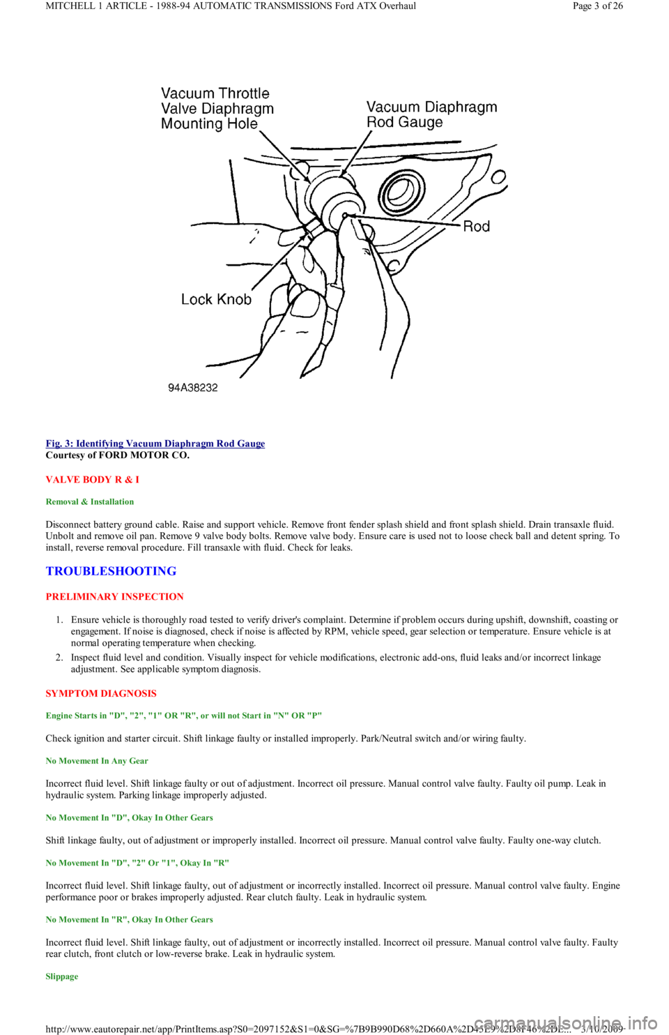
Fig. 3: Identifying Vacuum Diaphragm Rod Gauge
Courtesy of FORD MOTOR CO.
VALVE BODY R & I
Removal & Installation
Disconnect battery ground cable. Raise and support vehicle. Remove front fender splash shield and front splash shield. Drain transaxle fluid.
Unbolt and remove oil pan. Remove 9 valve body bolts. Remove valve body. Ensure care is used not to loose check ball and detent spring. To
install, reverse removal procedure. Fill transaxle with fluid. Check for leaks.
TROUBLESHOOTING
PRELIMINARY INSPECTION
1. Ensure vehicle is thoroughly road tested to verify driver's complaint. Determine if problem occurs during upshift, downshift, coasting or
engagement. If noise is diagnosed, check if noise is affected by RPM, vehicle speed, gear selection or temperature. Ensure vehicle is at
normal operating temperature when checking.
2. Inspect fluid level and condition. Visually inspect for vehicle modifications, electronic add-ons, fluid leaks and/or incorrect linkage
adjustment. See applicable symptom diagnosis.
SYMPTOM DIAGNOSIS
Engine Starts in "D", "2", "1" OR "R", or will not Start in "N" OR "P"
Check ignition and starter circuit. Shift linkage faulty or installed improperly. Park/Neutral switch and/or wiring faulty.
No Movement In Any Gear
Incorrect fluid level. Shift linkage faulty or out of adjustment. Incorrect oil pressure. Manual control valve faulty. Faulty oil pump. Leak in
hydraulic system. Parking linkage improperly adjusted.
No Movement In "D", Okay In Other Gears
Shift linkage faulty, out of adjustment or improperly installed. Incorrect oil pressure. Manual control valve faulty. Faulty one-way clutch.
No Movement In "D", "2" Or "1", Okay In "R"
Incorrect fluid level. Shift linkage faulty, out of adjustment or incorrectly installed. Incorrect oil pressure. Manual control valve faulty. Engine
performance poor or brakes improperly adjusted. Rear clutch faulty. Leak in hydraulic system.
No Movement In "R", Okay In Other Gears
Incorrect fluid level. Shift linkage faulty, out of adjustment or incorrectly installed. Incorrect oil pressure. Manual control valve faulty. Faulty
rear clutch, front clutch or low-reverse brake. Leak in hydraulic system.
Slippage
Page 3 of 26 MITCHELL 1 ARTICLE - 1988-94 AUTOMATIC TRANSMISSIONS Ford ATX Overhaul
3/10/2009 http://www.eautorepair.net/app/PrintItems.asp?S0=2097152&S1=0&SG=%7B9B990D68%2D660A%2D45E9%2D8F46%2DE
...
Page 436 of 454
Back To Article
T RANSMISSION SERVICING - A/T
1988-93 T RANSMISSION SERVICING Ford Motor Co. Autom atic T ransm ission
IDENTIFICATION
AUTOMATIC TRANSMISSION APPLICATIONS
LUBRICATION
SERVICE INTERVALS
Check fluid level at every engine oil change. Fluid, filter changes and band adjustments are not required under normal operation. Under severe
service operating conditions, change fluid every 30 months or 30,000 miles. Adjust band when fluid is changed.
CHECKING FLUID LEVEL
With transmission at normal operating temperature, place vehicle on level surface. Apply parking brake and run engine at idle. Run gearshift
lever through all positions, ending in Park. With engine running, fluid level should be between "F" and "L" marks. DO NOT overfill.
RECOMMENDED FLUID
Use Dexron-II ATF.
FLUID CAPACITIES
TRANSMISSION REFILL CAPACITIES
DRAINING & REFILLING
1. Remove undercover and side cover to gain access to transaxle oil pan. Remove drain plug and drain fluid. Remove oil pan and discard
gasket. Clean or replace filter screen as necessary. Tighten screen bolts to 71-97 INCH lbs. (8-11 N.m).
2. Install oil pan bolts. Tighten bolts to 44-71 INCH lbs. (5-8 N.m). On all models, install drain plug with NEW washer. Tighten plug to
29-40 ft. lbs. (39-54 N.m).
3. Install undercover and side cover. Add about 3 qts. of specified ATF through dipstick guide tube. DO NOT overfill. Run engine to
normal operating temperature and check fluid level.
ADJUSTMENTS
NEUTRAL SAFETY SWITCH
Combination neutral safety and back-up light switch is screwed into transaxle case. No adjustments are necessary.
SHIFT CONTROL CABLE
1. Disconnect negative battery cable. Remove shift console. Place shift lever in Park. Remove shift lever knob and lock nut. Remove 4 shift
quadrant attaching screws.
2. Loosen shift cable adjuster nuts until they reach end of cable threads. See Fig. 1
. Place shift lever in Park. Tighten lower adjustment
nut until it lightly touches "T" joint, then tighten upper adjustment nut to 80-97 INCH lbs. (9-11 N.m).
3. Lightly press selector push rod and make sure guide pin clearance is correct. See Fig. 2
. Check guide pin clearance when shift lever is
in Neutral and Drive. Readjust shift cable as necessary.
4. Install 4 shift quadrant attaching screws, shift lever knob, lock nut and shift console. Connect negative battery cable.
ModelTransmission
FestivaATX/3HAT
NOTE:Capacities given are approxim ate refill am ounts that apply to overhaul situation. Correct fluid level
should be determ ined by m ark on dipstick.
ApplicationQts. (L)
ATX/3HAT5.6 (5.3)
CAUT ION: DO NOT use any type of gasket sealer or RT V on oil pan gasket. DO NOT overtighten.
CAUT ION: After com pleting linkage adjustm ents, be sure neutral safety switch operates properly. With parking
brake and service brakes applied, try to start engine in each gear position. Engine m ust crank only
when gearshift lever is in Neutral and Park.
Page 1 of 4 MITCHELL 1 ARTICLE - TRANSMISSION SERVICING - A/T 1988-93 TRANSMISSION SERVICING Ford Motor Co. Aut
...
3/10/2009 http://www.eautorepair.net/app/PrintItems.asp?S0=2097152&S1=0&SG=%7B9B990D68%2D660A%2D45E9%2D8F46%2DE
...
Page 439 of 454
1. Inspect wiring and components for shorts, corrosion, overheating, loose connections, or any other damage. Check 10-amp METER fu se.
Disconnect downshift solenoid.
2. With key off, voltage measured at Black/Blue wire should be zero volts. With key on and accelerator pedal fully depressed, voltage
should be greater than 10 volts. If Black/Blue wire is okay, remove downshift solenoid.
3. Apply battery voltage to downshift solenoid connector and ground case. Control rod should move freely when solenoid case is
grounded. If control rod does not move freely, replace downshift solenoid.
VACUUM DIAPHRAGM ROD
If transaxle shift points are incorrect, check for a defective vacuum diaphragm and replace if necessary. If diaphragm is operating correctly,
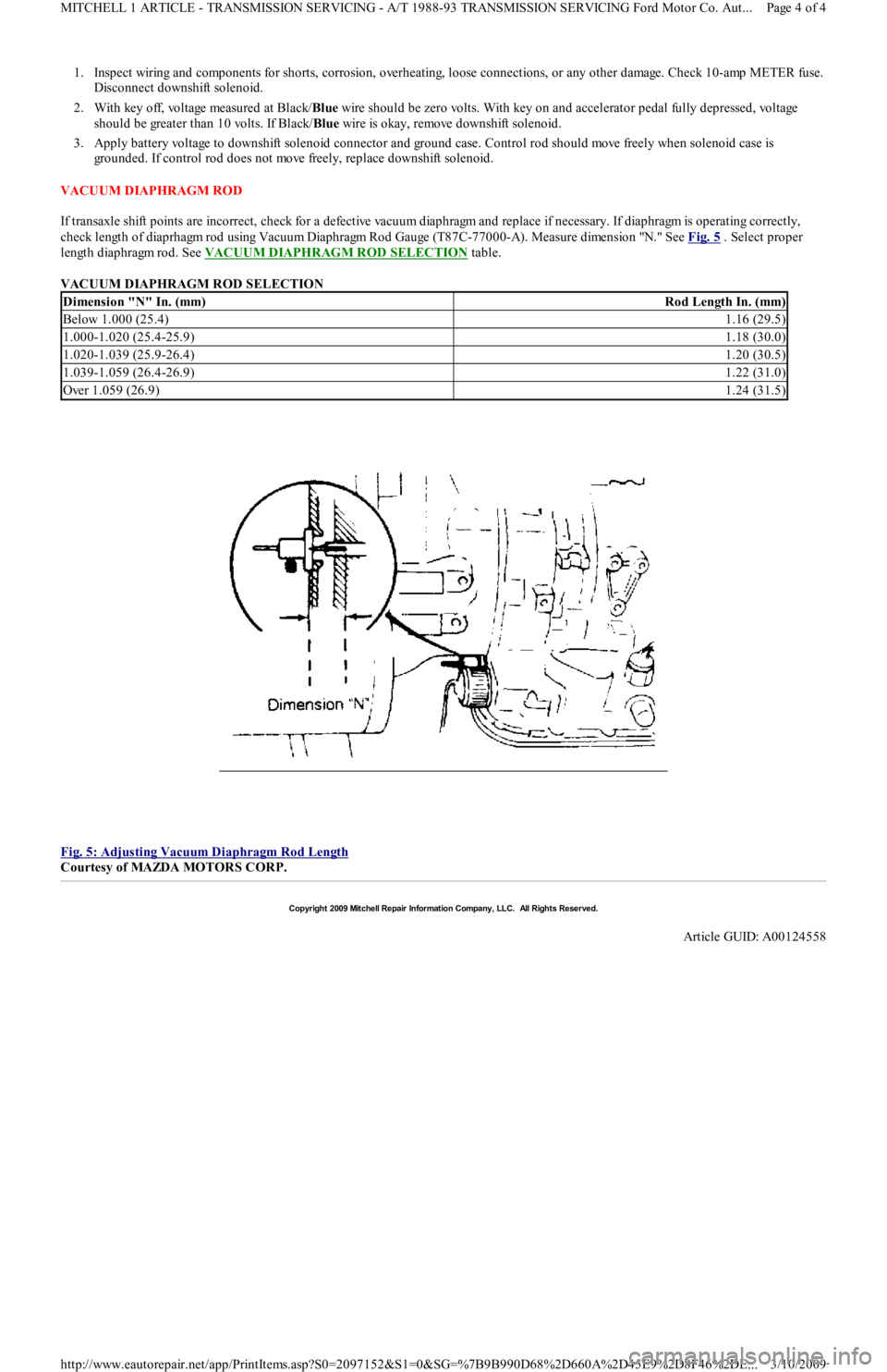
check length of diaprhagm rod using Vacuum Diaphragm Rod Gauge (T87C-77000-A). Measure dimension "N." See Fig. 5
. Select proper
length diaphragm rod. See VACUUM DIAPHRAGM ROD SELECTION
table.
VACUUM DIAPHRAGM ROD SELECTION
Fig. 5: Adjusting Vacuum Diaphragm Rod Length
Courtesy of MAZDA MOTORS CORP.
Dimension "N" In. (mm)Rod Length In. (mm)
Below 1.000 (25.4)1.16 (29.5)
1.000-1.020 (25.4-25.9)1.18 (30.0)
1.020-1.039 (25.9-26.4)1.20 (30.5)
1.039-1.059 (26.4-26.9)1.22 (31.0)
Over 1.059 (26.9)1.24 (31.5)
Copyr ight 2009 Mitchell Repair Information Company, LLC. All Rights Reserved.
Article GUID: A00124558
Page 4 of 4 MITCHELL 1 ARTICLE - TRANSMISSION SERVICING - A/T 1988-93 TRANSMISSION SERVICING Ford Motor Co. Aut
...
3/10/2009 http://www.eautorepair.net/app/PrintItems.asp?S0=2097152&S1=0&SG=%7B9B990D68%2D660A%2D45E9%2D8F46%2DE
...