1991 ACURA NSX seats
[x] Cancel search: seatsPage 1031 of 1640
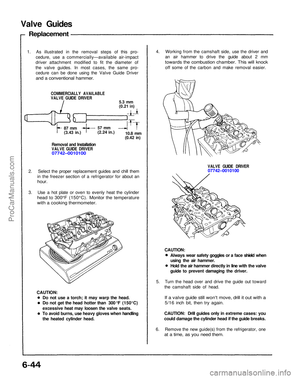
4. Working from the camshaft side, use the driver and
an air hammer to drive the guide about 2 mm
towards the combustion chamber. This will knock
off some of the carbon and make removal easier.
VALVE GUIDE DRIVER
07742–0010100
5. Turn the head over and drive the guide out toward the camshaft side of head.
If a valve guide still won't move, drill it out with a
5/16 inch bit, then try again.
CAUTION: Drill guides only in extreme cases: you
could damage the cylinder head if the guide breaks.
6. Remove the new guide(s) from the refrigerator, one
at a time, as you need them.
Do not use a torch; it may warp the head.
Do not get the head hotter than 300 °F (150°C)
excessive heat may loosen the valve seats.
To avoid burns, use heavy gloves when handling
the heated cylinder head.
Valve Guides
Replacement
1. As illustrated in the removal steps of this pro- cedure, use a commercially—available air-impact
driver attachment modified to fit the diameter of
the valve guides. In most cases, the same pro- cedure can be done using the Valve Guide Driver
and a conventional hammer.
COMMERCIALLY AVAILABLE
VALVE GUIDE DRIVER
5.3 mm
(0.21
in)
87 mm
(3.43 in.)
57 mm
(2.24 in.)
10.8
mm
(0.42
in)
Removal and Installation
VALVE GUIDE DRIVER
07742–0010100
2. Select the proper replacement guides and chill them in the freezer section of a refrigerator for about an
hour.
3. Use a hot plate or oven to evenly heat the cylinder
head to 300°F (150°C). Monitor the temperature
with a cooking thermometer.
CAUTION: Always wear safety goggles or a face shield when
using the air hammer.
Hold the air hammer directly in line with the valve
guide to prevent damaging the driver.
CAUTION:ProCarManuals.com
Page 1034 of 1640
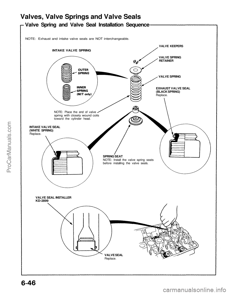
Valves, Valve Springs and Valve Seals
Valve Spring and Valve Seal Installation Sequence
NOTE: Exhaust and intake valve seals are NOT interchangeable.
INTAKE VALVE SPRING
NOTE: Place the end of valve
spring with closely wound coils
toward the cylinder head.
INTAKE VALVE SEAL
(WHITE SPRING)
Replace.
VALVE SEAL INSTALLER
KD-2899
VALVE SEAL
Replace.
VALVE KEEPERS
VALVE SPRING
RETAINER
VALVE SPRING
EXHAUST VALVE SEAL
(BLACK SPRING)
Replace.
SPRING SEAT
NOTE: Install the valve spring seats
before installing the valve seals.ProCarManuals.com
Page 1318 of 1640
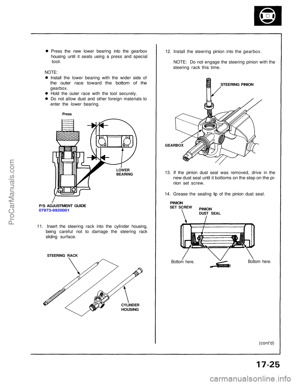
Press the new lower bearing into the gearbox
housing until it seats using a press and special
tool.
NOTE:
Install the lower bearing with the wider side of
the outer race toward the bottom of the
gearbox. Hold the outer race with the tool securely.
Do not allow dust and other foreign materials to
enter the lower bearing.
Press
LOWER
BEARING
P/S ADJUSTMENT GUIDE
07973-6920001
11. Insert the steering rack into the cylinder housing, being careful not to damage the steering rack
sliding surface.
STEERING RACK
CYLINDER
HOUSING
12. Install the steering pinion into the gearbox.
NOTE: Do not engage the steering pinion with the
steering rack this time.
STEERING PINION
GEARBOX
13. If the pinion dust seal was removed, drive in the
new dust seal until it bottoms on the step on the pi-
nion set screw.
14. Grease the sealing lip of the pinion dust seal.
PINION
SET SCREW
PINION
DUST SEAL
Bottom here.
Bottom here.
(cont'd)ProCarManuals.com
Page 1371 of 1640
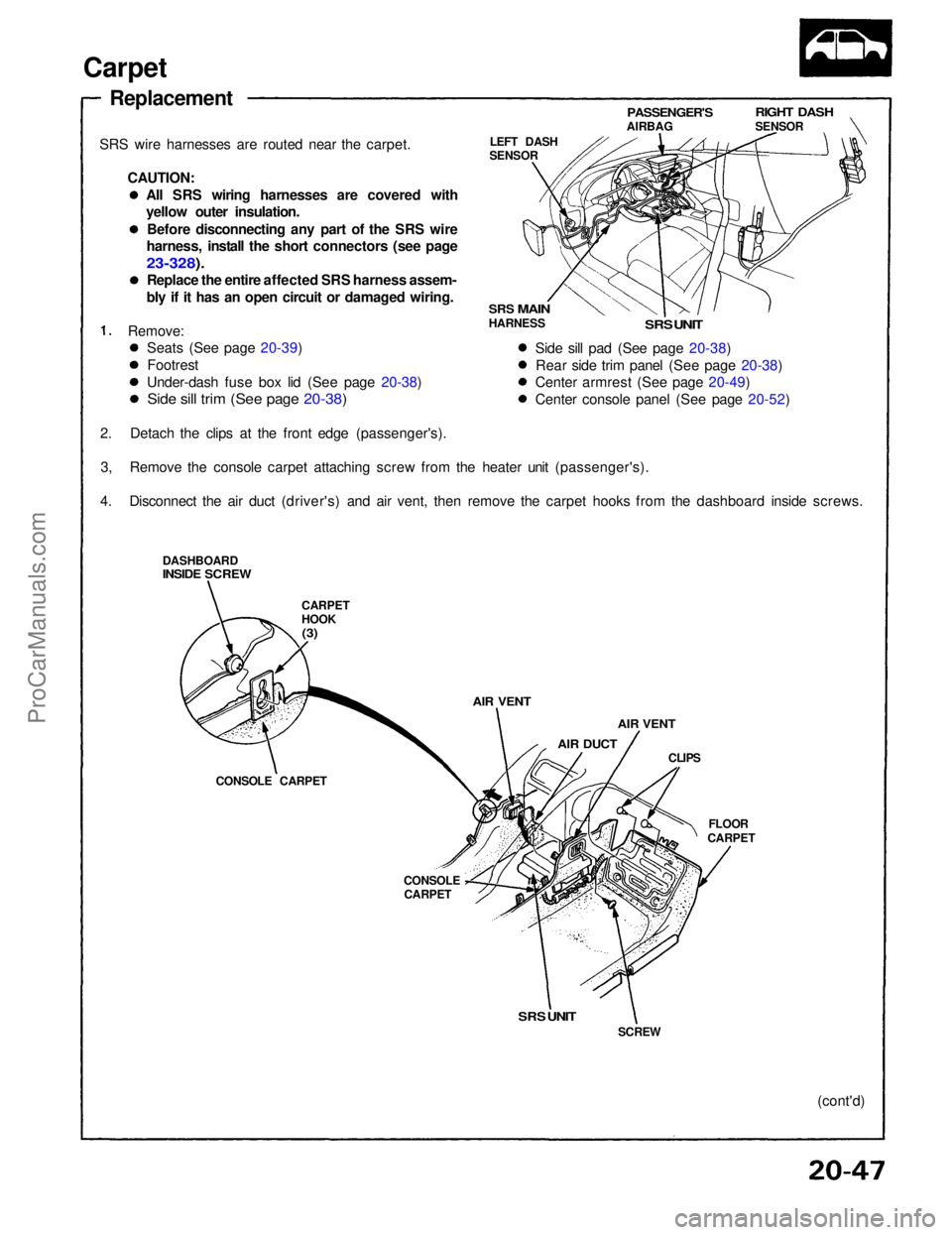
Carpet
Replacement
SRS wire harnesses are routed near the carpet. CAUTION:
Remove:
2. Detach the clips at the front edge (passenger's). 3, Remove the console carpet attaching screw from the heater unit (passenger's).
4. Disconnect the air duct (driver's) and air vent, then remove the carpet hooks from the dashboard inside screws.
DASHBOARD
INSIDE SCREW
CARPET
HOOK
(3)
AIR VENT
AIR DUCT
AIR VENT
CLIPS
FLOOR
CARPET
CONSOLE
CARPET
CONSOLE CARPET LEFT DASH
SENSOR
PASSENGER'S
AIRBAG
RIGHT DASH
SENSOR
SRS
MAIN
HARNESS
SRS UNIT
Side sill pad (See page 20-38) Rear side trim panel (See page 20-38)
Center armrest (See page 20-49)
Center console panel (See page 20-52)
SRS UNIT
SCREW
(cont'd)
Seats (See page 20-39)
Footrest
Under-dash fuse box lid (See page 20-38)
Side sill trim (See page 20-38)
All SRS wiring harnesses are covered with
yellow outer insulation.
Before disconnecting any part of the SRS wire
harness, install the short connectors (see page
23-328).
Replace the entire affected SRS harness assem-
bly if it has an open circuit or damaged wiring.ProCarManuals.com
Page 1379 of 1640
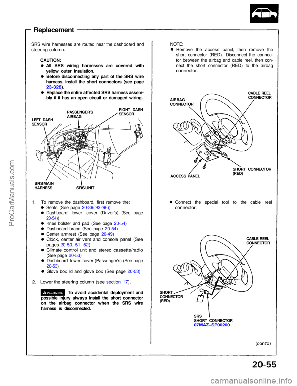
Replacement
SRS wire harnesses are routed near the dashboard and
steering column.
CAUTION:All SRS wiring harnesses are covered with
yellow outer insulation.Before disconnecting any part of the SRS wire
harness, install the short connectors (see page
23-328).
Replace the entire affected SRS harness assem-
bly if it has an open circuit or damaged wiring.
LEFT DASH
SENSOR
PASSENGER'S
AIRBAG
RIGHT DASH
SENSOR
SRS MAIN
HARNESS
SRS UNIT
1. To remove the dashboard, first remove the: Seats (See page 20-39('93-'96))
Dashboard lower cover (Driver's) (See page
20-54))
Knee bolster and pad (See page 20-54)
Dashboard brace (See page 20-54)
Center armrest (See page 20-49)
Clock, center air vent and console panel (See
pages 20-50, 51, 52)
Climate control unit and stereo cassette/radio
(See page 20-53)Dashboard lower cover (Passenger's) (See page
20-53)
Glove box lid and glove box (See page 20-53)
2. Lower the steering column (see section 17).
To avoid accidental deployment and NOTE:
Remove the access panel, then remove the
short connector (RED). Disconnect the connec-
tor between the airbag and cable reel, then con- nect the short connector (RED) to the airbag
connector.
AIRBAG
CONNECTOR
CABLE REEL
CONNECTOR
ACCESS PANEL SHORT CONNECTOR
(RED)
Connect the special tool to the cable reel
connector.
CABLE REEL
CONNECTOR
SHORT
CONNECTOR
(RED)
SRS
SHORT CONNECTOR
07MAZ–SP00200
(cont'd)
possible injury always install the short connector
on the airbag connector when the SRS wire
harness is disconnected.ProCarManuals.com
Page 1577 of 1640
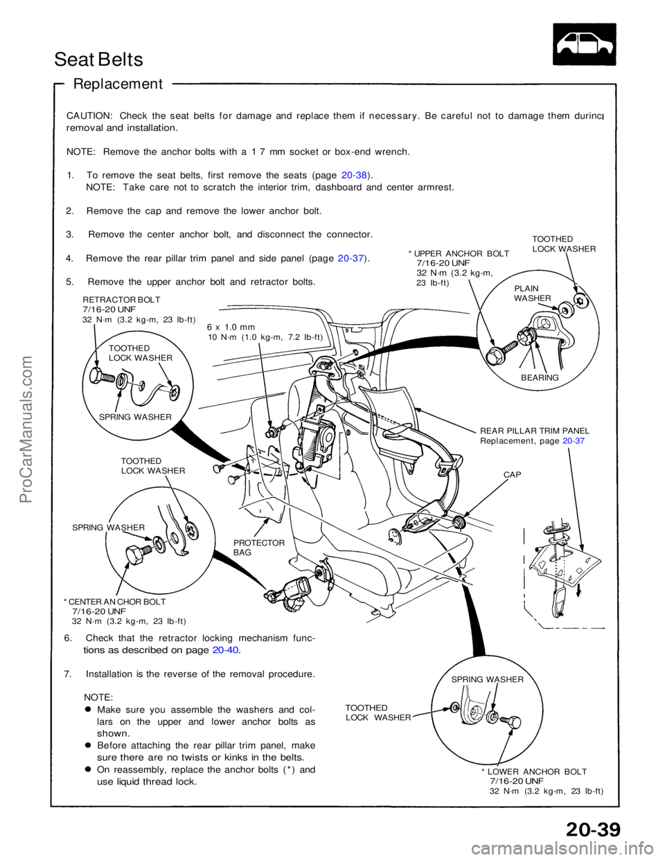
Seat Belts
Replacement
CAUTION: Check the seat belts for damage and replace them if necessary. Be careful not to damage them durinc
removal and installation.
NOTE: Remove the anchor bolts with a 1 7 mm socket or box-end wrench.1. To remove the seat belts, first remove the seats (page 20-38). NOTE: Take care not to scratch the interior trim, dashboard and center armrest.
2. Remove the cap and remove the lower anchor bolt.
3. Remove the center anchor bolt, and disconnect the connector.
4. Remove the rear pillar trim panel and side panel (page 20-37). 5. Remove the upper anchor bolt and retractor bolts. RETRACTOR BOLT
7/16-20 UNF
32 N·m (3.2 kg-m, 23 Ib-ft) 6 x 1.0 mm
10 N·m (1.0 kg-m, 7.2 Ib-ft)
TOOTHED
LOCK WASHER
SPRING WASHER TOOTHEDLOCK WASHER
SPRING WASHER
PROTECTOR
BAG
* CENTER AN CHOR BOLT
7/16-20 UNF
32 N·m (3.2 kg-m, 23 Ib-ft)
6. Check that the retractor locking mechanism func-
tions as described on page 20-40.
7. Installation is the reverse of the removal procedure.
NOTE:
Make sure you assemble the washers and col-
lars on the upper and lower anchor bolts as
shown.
Before attaching the rear pillar trim panel, make
sure there are no twists or kinks in the belts.
On reassembly, replace the anchor bolts (*) and
use liquid thread lock.
TOOTHED
LOCK WASHER
* LOWER ANCHOR BOLT
7/16-20 UNF
32 N·m (3.2 kg-m, 23 Ib-ft)
SPRING WASHER
CAP
REAR PILLAR TRIM PANEL
Replacement, page 20-37
BEARING
PLAIN
WASHER
* UPPER ANCHOR BOLT
7/16-20 UNF
32 N·m
(3.2 kg-m,
23 Ib-ft) TOOTHED
LOCK WASHERProCarManuals.com
Page 1579 of 1640
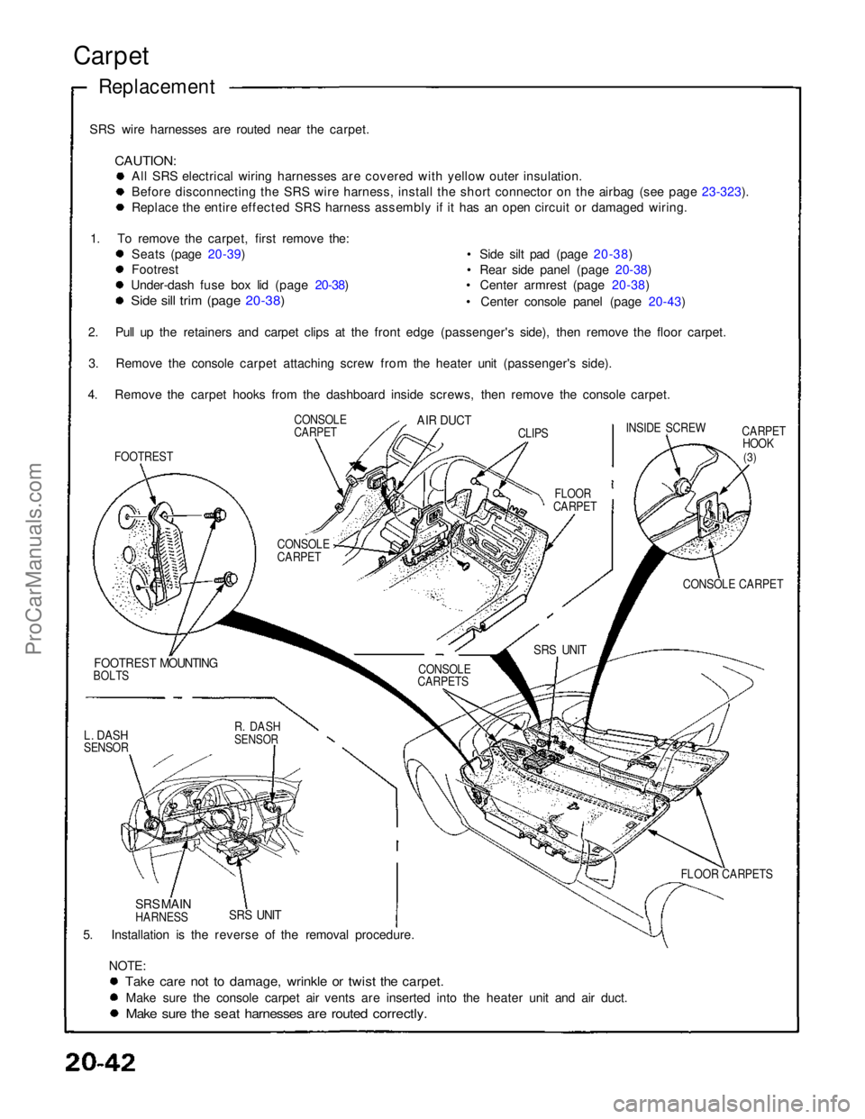
SRS wire harnesses are routed near the carpet.
CAUTION:
All SRS electrical wiring harnesses are covered with yellow outer insulation.
Before disconnecting the SRS wire harness, install the short connector on the airbag (see page 23-323).
Replace the entire effected SRS harness assembly if it has an open circuit or damaged wiring.
1. To remove the carpet, first remove the: Seats (page 20-39)
Footrest
Under-dash fuse box lid (page 20-38)
Side sill trim (page 20-38)
• Side silt pad (page 20-38)
• Rear side panel (page 20-38)
• Center armrest (page 20-38)
• Center console panel (page 20-43)
CARPETHOOK
(3)
CONSOLE CARPET
FOOTREST MOUNTING
BOLTS
5. Installation is the reverse of the removal procedure. NOTE:
Take care not to damage, wrinkle or twist the carpet.
Make sure the console carpet air vents are inserted into the heater unit and air duct.
Make sure the seat harnesses are routed correctly.
Carpet
Replacement
SRS UNIT
SRS MAIN
HARNESS FLOOR CARPETS
SRS UNIT
CONSOLE
CARPETS
CONSOLE
CARPET
FLOOR
CARPET INSIDE SCREW
CLIPS
AIR DUCT
CONSOLE
CARPET
FOOTREST
2. Pull up the retainers and carpet clips at the front edge (passenger's side), then remove the floor carpet.
3. Remove the console carpet attaching screw from the heater unit (passenger's side).
4. Remove the carpet hooks from the dashboard inside screws, then remove the console carpet.
L. DASH
SENSOR
R. DASH
SENSORProCarManuals.com
Page 1582 of 1640
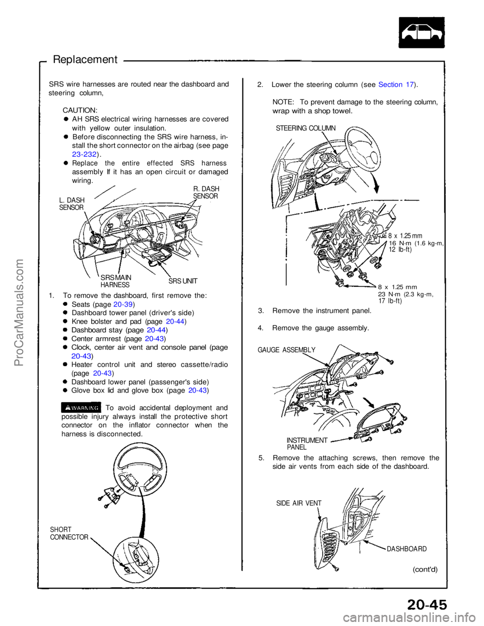
Replacement
SRS wire harnesses are routed near the dashboard and
steering column,
CAUTION:
AH SRS electrical wiring harnesses are covered
with yellow outer insulation.
Before disconnecting the SRS wire harness, in-
stall the short connector on the airbag (see page
23-232).
Replace the entire effected SRS harness
assembly If it has an open circuit or damaged
wiring.
R. DASH
SENSOR
L. DASH
SENSOR
SRS MAIN
HARNESS
SRS
UNIT
1. To remove the dashboard, first remove the: Seats (page 20-39)
Dashboard tower panel (driver's side)
Knee bolster and pad (page 20-44)
Dashboard stay (page 20-44)
Center armrest (page 20-43)
Clock, center air vent and console panel (page
20-43)
Heater control unit and stereo cassette/radio
(page 20-43)
Dashboard lower panel (passenger's side)
Glove box lid and glove box (page 20-43)
To avoid accidental deployment and
possible injury always install the protective short
connector on the inflator connector when the
harness is disconnected.
SHORT
CONNECTOR
(cont'd)
DASHBOARD
SIDE AIR VENT
5. Remove the attaching screws, then remove the
side air vents from each side of the dashboard.
INSTRUMENT
PANEL
GAUGE ASSEMBLY
3. Remove the instrument panel.
4. Remove the gauge assembly.
8 x
1.25
mm
23 N·m
(2.3 kg-m,
17 lb-ft)
8 x 1.25 mm
16 N·m
(1.6 kg-m,
12 Ib-ft)
STEERING COLUMN
2. Lower the steering column (see Section 17).
NOTE: To prevent damage to the steering column,
wrap with a shop towel.ProCarManuals.com