Page 1212 of 1640
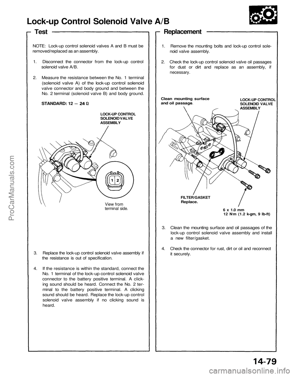
Lock-up Control Solenoid Valve A/B
Test
NOTE: Lock-up control solenoid valves A and B must be
removed/replaced as an assembly.
1. Disconnect the connector from the lock-up control solenoid valve A/B.
2. Measure the resistance between the No. 1 terminal
(solenoid valve A) of the lock-up control solenoid
valve connector and body ground and between the No. 2 terminal (solenoid valve B) and body ground.
View from
terminal side.
3. Replace the lock-up control solenoid valve assembly if the resistance is out of specification.
4. If the resistance is within the standard, connect the
No. 1 terminal of the lock-up control solenoid valve
connector to the battery positive terminal. A click-
ing sound should be heard. Connect the No. 2 ter-
minal to the battery positive terminal. A clicking
sound should be heard. Replace the lock-up controlsolenoid valve assembly if no clicking sound is
heard.
3. Clean the mounting surface and oil passages of the
lock-up control solenoid valve assembly and install
a new filter/gasket.
4. Check the connector for rust, dirt or oil and reconnect it securely.
6 x 1.0 mm
12 N.m (1.2 k-gm, 9 Ib-ft)
FILTER/GASKET
Replace.
LOCK-UP CONTROL
SOLENOID VALVE
ASSEMBLYClean mounting surface
and oil passages.
1. Remove the mounting bolts and lock-up control sole-
noid valve assembly.
2. Check the lock-up control solenoid valve oil passages for dust or dirt and replace as an assembly, if
necessary.
Replacement
STANDARD: 12
LOCK-UP CONTROL
SOLENOID VALVE
ASSEMBLYProCarManuals.com
Page 1213 of 1640
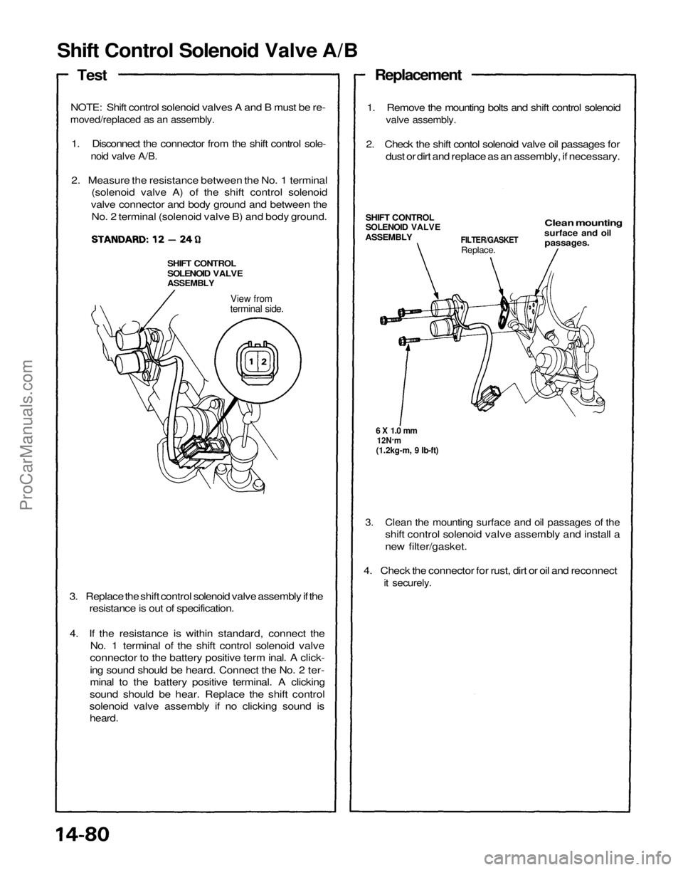
Shift Control Solenoid Valve A/B
Test
NOTE: Shift control solenoid valves A and B must be re-
moved/replaced as an assembly.
1. Disconnect the connector from the shift control sole-
noid valve A/B.
2. Measure the resistance between the No. 1 terminal (solenoid valve A) of the shift control solenoid
valve connector and body ground and between the No. 2 terminal (solenoid valve B) and body ground.
SHIFT CONTROL
SOLENOID VALVE
ASSEMBLY
View from
terminal side.
3. Replace the shift control solenoid valve assembly if the resistance is out of specification.
4. If the resistance is within standard, connect the No. 1 terminal of the shift control solenoid valve
connector to the battery positive term inal. A click-
ing sound should be heard. Connect the No. 2 ter-
minal to the battery positive terminal. A clicking
sound should be hear. Replace the shift control
solenoid valve assembly if no clicking sound is heard.
3. Clean the mounting surface and oil passages of the
shift control solenoid valve assembly and install a
new filter/gasket.
4. Check the connector for rust, dirt or oil and reconnect
it securely.
6 X 1.0 mm
12N .
m
(1.2kg-m, 9 Ib-ft)
FILTER/GASKET
Replace.
Clean mounting
surface and oil
passages.
SHIFT CONTROL
SOLENOID VALVE
ASSEMBLY
1. Remove the mounting bolts and shift control solenoid
valve assembly.
2. Check the shift contol solenoid valve oil passages for dust or dirt and replace as an assembly, if necessary.
ReplacementProCarManuals.com
Page 1238 of 1640
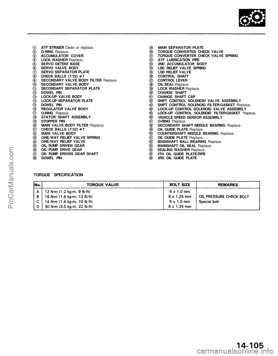
ATF STRAIER Clean or replace.
O-RING
Replace.
ACCUMULATOR COVER
LOCK WASHER
Replace.
SERVO DETENT BASE
SERVO VALVE BODY
SERVO SEPARATOR PLATE CHECK BALLS (7/32) 7
SECONDARY VALVE BODY FILTER
Replace.
SECONDARY VALVE BODY
SECONDARY SEPARATOR PLATE
DOWEL PIN
LOCK-UP VALVE BODY
LOCK-UP SEPARATOR PLATE
DOWEL PIN REGULATOR VALVE BODY
O-RING
Replace.
STATOR SHAFT ASSEMBLY
STOPPER PIN
MAIN VALVE BODY FILTER
Replace. CHECK BALLS (7/32) 7
MAIN VALVE BODY
ONE-WAY RELIEF VALVE SPRING
ONE-WAY RELIEF VALVE
OIL PUMP DRIVEN GEAR
OIL PUMP DRIVE GEAR
OIL PUMP DRIVEN GEAR SHAFT
DOWEL PIN MAIN SEPARATOR PLATE
TORQUE CONVERTER CHECK VALVE
TORQUE CONVERTER CHECK VALVE SPRING ATF LUBRICATION PIPE
2ND ACCUMULATOR BODY
LSD RELIEF VALVE SPRINGLSD RELIEF VALVE
CONTROL SHAFT
CONTROL LEVER
OIL SEAL
Replace.
LOCK WASHER
Replace.
CHANGE SHAFT
CHANGE SHAFT CAP
SHIFT CONTROL SOLENOID VALVE ASSEMBLY
SHIFT CONTROL SOLENOID FILTER/GASKET
Replace.
LOCK-UP CONTROL SOLENOID VALVE ASSEMBLY
LOCK-UP CONTROL SOLENOID FILTER/GASKET
Replace.
VEHICLE SPEED SENSOR ASSEMBLY
O-RING Replace.
SECONDARY SHAFT NEEDLE BEARING
Replace.
OIL GUIDE PLATE
Replace.
COUNTERSHAFT NEEDLE BEARING
Replace.
OIL GUIDE PLATE
Replace.
MAINSHAFT BALL BEARING
Replace.
MAINSHAFT OIL SEAL
Replace.
SEALING WASHER
Replace.
4TH OIL GUIDE PLATE/PIPE
3RD OIL GUIDE PLATE
TORQUE SPECIFICATIONProCarManuals.com
Page 1461 of 1640
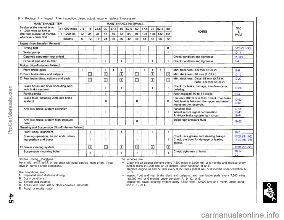
R = Replace I = Inspect After inspection, clean, adjust, repair or replace if necessary.
NOTES
SEC
&
PAGE
Severe Driving Conditions Items with an orin the chart will need service more often, if you
drive in some severe conditions.
The conditions are:
A. Repeated short distance driving.
B. Dusty conditions.
C. Severe cold weather.
D. Areas with road salt or other corrosive materials.
E. Rough or muddy roads. The services are:
Clean the air cleaner element every 7,500 miles (12,000 km) or 6 months and replace every
30,000 miles (48,000 km) or 24 months under condition B or E. Replace engine oil and oil filter every 3,750 miles (6,000 km) or 3 months under condition A
or B.
Inspect front and rear brake discs and calipers, and rear brake pads every 7,500 miles (12,000 km) or 6 months under condition A, B, D, or E.
Inspect the power steering system every 7,500 miles (12,000 km) or 6 month under condi-
tion B, C, or E. 6-23 ('91-'93)10-11
11-127
9-4
19-6
19-10
19-20
19-18
19-26
19-4
19-62
19-69
19-41
19-43
19-44
19-62
18-6
17-21 ('91-'93)
17-30 ('91-'93)
17-31 ('91-'93)
18-14,
30
ProCarManuals.com
Page 1462 of 1640
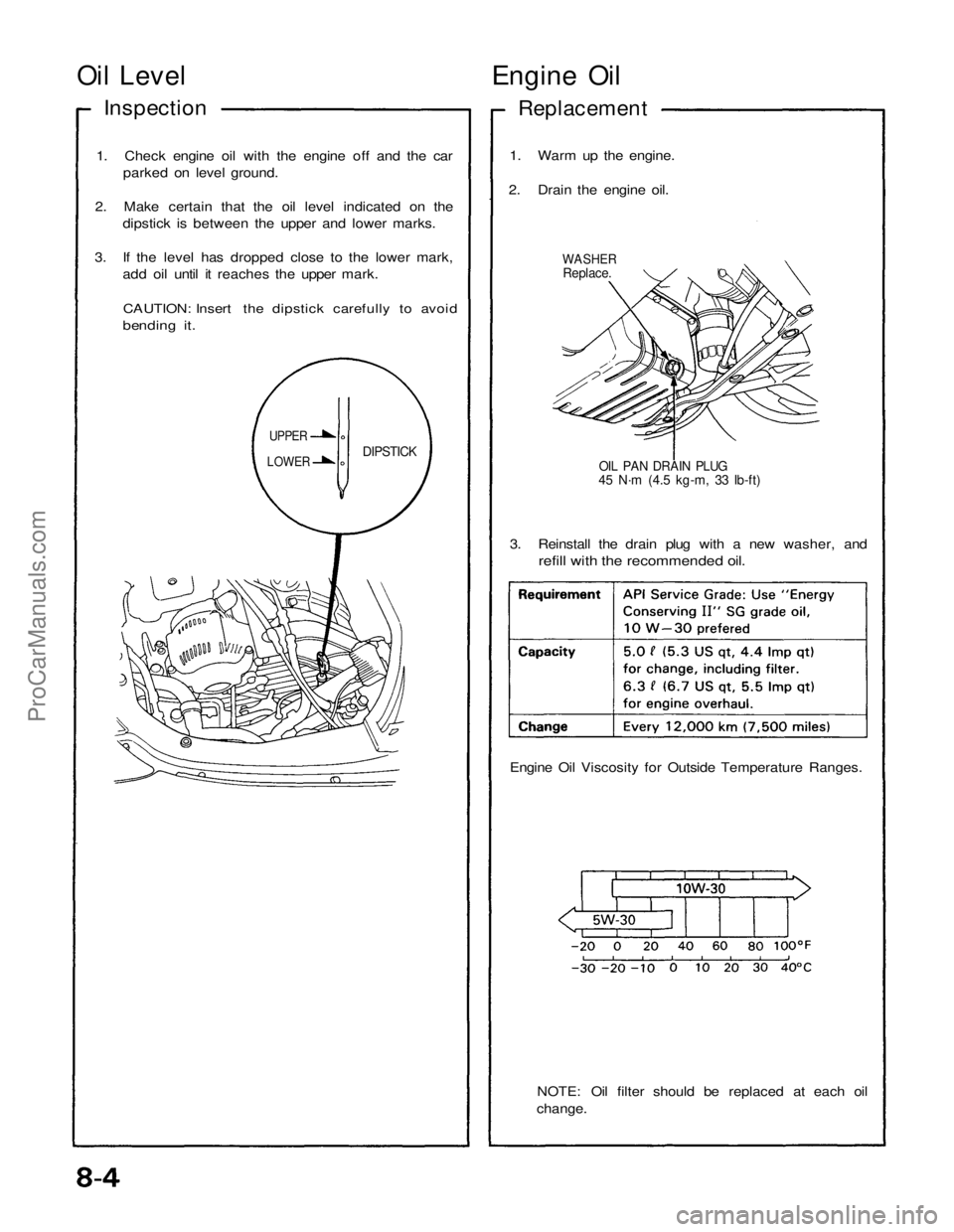
Oil Level
Engine Oil
Inspection
Replacement
1. Check engine oil with the engine off and the car parked on level ground.
2. Make certain that the oil level indicated on the dipstick is between the upper and lower marks.
3. If the level has dropped close to the lower mark, add oil until it reaches the upper mark.
CAUTION: Insert the dipstick carefully to avoid
bending it.
1. Warm up the engine.
2. Drain the engine oil.
WASHER
Replace.
OIL PAN DRAIN PLUG
45 N·m (4.5 kg-m, 33 Ib-ft)
DIPSTICK
UPPER
LOWER
3. Reinstall the drain plug with a new washer, and
refill with the recommended oil.
Engine Oil Viscosity for Outside Temperature Ranges.
NOTE: Oil filter should be replaced at each oil
change.ProCarManuals.com
Page 1508 of 1640
Fuel Supply System
Fuel Pump
Description
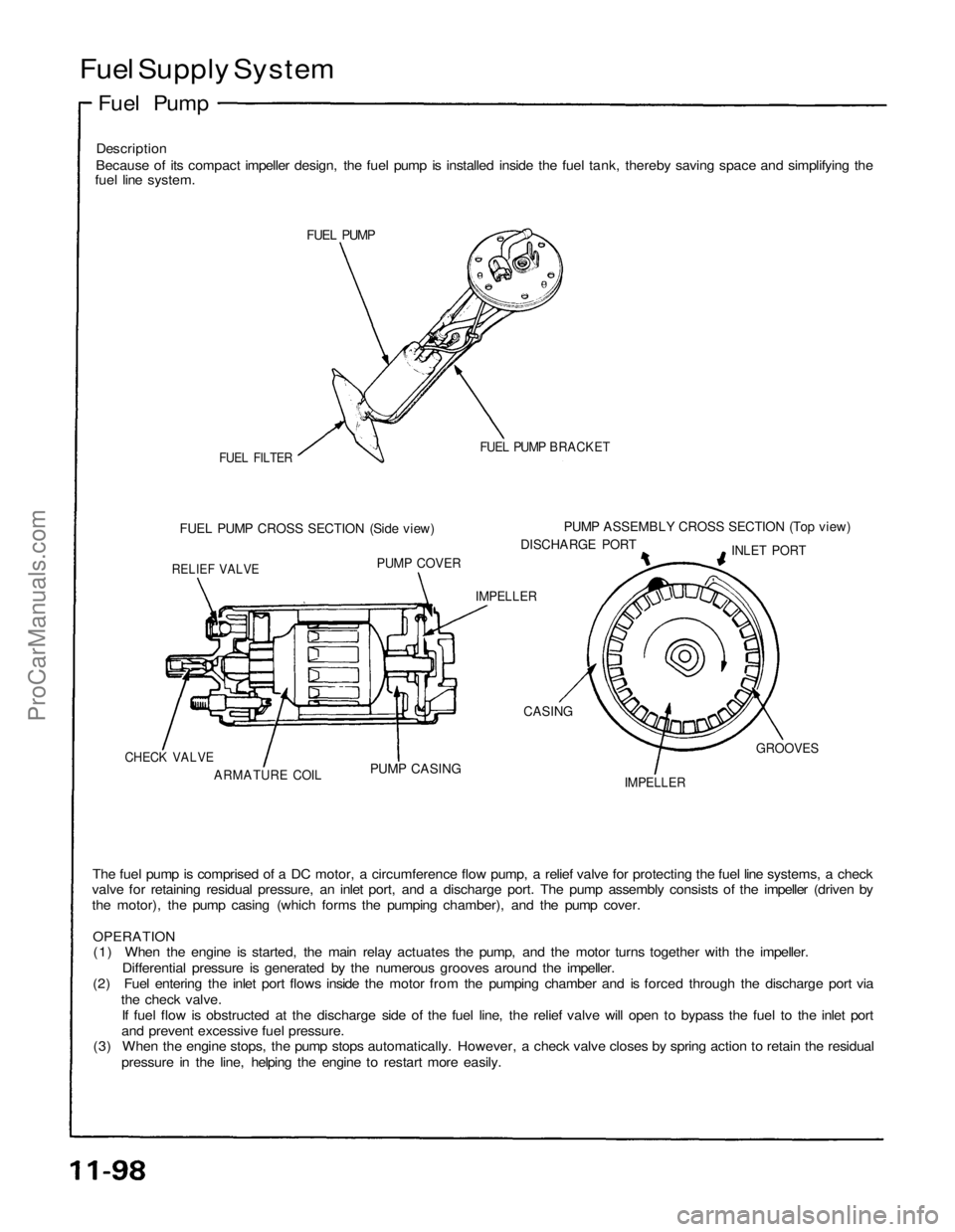
Because of its compact impeller design, the fuel pump is installed inside the fuel tank, thereby saving space and simplifying the
fuel line system.
FUEL PUMP
FUEL FILTER
FUEL PUMP BRACKET
FUEL PUMP CROSS SECTION (Side view)
PUMP ASSEMBLY CROSS SECTION (Top view)
DISCHARGE PORT
INLET PORT
RELIEF VALVE
PUMP COVER
IMPELLER
CASING
IMPELLER
GROOVES
PUMP CASING
ARMATURE COIL
CHECK VALVE
The fuel pump is comprised of a DC motor, a circumference flow pump, a relief valve for protecting the fuel line systems, a check
valve for retaining residual pressure, an inlet port, and a discharge port. The pump assembly consists of the impeller (driven by
the motor), the pump casing (which forms the pumping chamber), and the pump cover.
OPERATION
(1) When the engine is started, the main relay actuates the pump, and the motor turns together with the impeller.
Differential pressure is generated by the numerous grooves around the impeller.
(2) Fuel entering the inlet port flows inside the motor from the pumping chamber and is forced through the discharge port via
the check valve.
If fuel flow is obstructed at the discharge side of the fuel line, the relief valve will open to bypass the fuel to the inlet port
and prevent excessive fuel pressure.
(3) When the engine stops, the pump stops automatically. However, a check valve closes by spring action to retain the residual
pressure in the line, helping the engine to restart more easily.ProCarManuals.com
Page:
< prev 1-8 9-16 17-24