Page 1003 of 2103
MANUAL TRANSAXLE Case-
Reverse idler
Screws (2)A
TSBRevision
reverse fork bracket and reverse cam lockout as-
sembly. Tighten screws to 11 Nm (9.6
torque.
differential into gear case.
Page 1004 of 2103

TRANSAXLE
G E N E R A L R U L E S O N
(3)
(4)
Take extreme care when removing, and installing bearing
cups and cones. Use only
arbor for installation,
as a hammer may not properly* align the
or cone. Burrs or nicks on the bearing
give a end
play reading while gauging. for proper shims. Impro perly
seated bearing cups and cones are subject to low mi leage’
failure.
Bearing cups and ‘cones should be replaced if they
signs of pitting or heat distress., If distress seen on’
either the cup or bearing rollers, both cone must
be replaced.
Bearing preload and drag torque specifications
maintained to avoid premature’
(original) bearing may lose up to drag
torque offer break in. All bearing, adjustments
made with no other component
mesh.
Replace bearings as a pair. For
bearing is defective, replace both differential.
If one input shaft bearing is defective; ‘replace b oth input
s h a f t b e a r i n g s .
Bearing cones must not be reused if
Turning torque readings should be while smooth-
ly rotating in either direction,,
TSB Revision
Page 1005 of 2103

Differential Bearing
MANUAL TRANSAXLE Preload Adjustment
DIFFERENTIAL BEARING
ADJUSTMENT
True bearing turning torque readings can only be obtained
with the gear train removed from the case.
(1) Remove bearing cup and existing shim from clutc h
housing case.
(2) Press in new bearing cup into bell housing case (or use
a cup that has been ground down on the outer edge
for ease of measurement).
(3) Press in new bearing cup into gear case side.
(4) Lubricate differential bearings with SAE
engine
oil. Install differential assembly in transaxle gear case.
Install clutch bell housing over gear case.
and
torque case bolts to 29 Nm (21
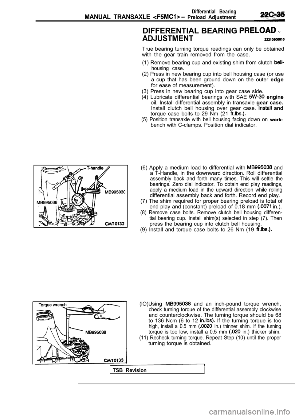
(5) Position transaxle with bell housing facing dow n on work-
bench with C-clamps. Position dial indicator.
(6) Apply a medium load to differential with
and
a T-Handle, in the downward direction. Roll differe ntial
assembly back and forth many times. This will settl e the
bearings. Zero dial indicator. To obtain end play r eadings,
apply a medium load in the upward direction while r olling
differential assembly back and forth. Record end play.
(7) The shim required for proper bearing preload is total of
end play and (constant) preload of 0.18 mm
in.).
(8) Remove case bolts. Remove clutch bell housing d ifferen-
tial bearing cup. Install shim(s) selected in step (7). Then
press the bearing cup into clutch bell housing.
(9) Install and torque case bolts to 26 Nm (19
(lO)Using and an inch-pound torque wrench,
check turning torque of the differential assembly c lockwise
and counterclockwise. The turning torque should be 68
to 136 Ncm (6 to 12
If the turning torque is too
high, install a 0.5 mm in.) thinner shim. If the turning
torque is too low, install a 0.5 mm in.) thicker shim.
(11) Recheck turning torque. Repeat Step (10) until the proper
turning torque is obtained.
TSB Revision
Page 1011 of 2103
AUTOMATIC TRANSAXLE ENGINE . .
(TURBO) ENGINE> General Information’ .
GENERAL INFORMATION
The automatic transaxles come in two models, namely, and These transaxles
are essentially the same as the conventional models .
FWD
Reverse
Final ratiogear
Speedometer gear ratio (driven/drive)
AWD
Model
Applicable engine
Torque converter Type
Engine stall speed
Gear ratio
Reverse
Reduction ratio Primary Front differential
Transfer
Speedometer gear ratio (driven/drive)
0.6850.685,
2.1762.176
4.350
4.376
Specifications
Electronically controlled full-automatic
with torque converter clutch
2.551
1.488
1
0.685
2.176
1.228
3.550
1.074
TSB Revision
Page 1013 of 2103
AUTOMATIC TRANSAXLE ENGINE
(TURBO) AND ENGINE> General tnformation
SECTIONAL VIEW
TorqueconverterOil pump
I
Front clutch
I
Low-reverse
Rear clutch Planetarygear
Ibrake
Torqueclutch
TSBRevisionI-
End
T r a n s f e rdriven gear
drive gear
Transfer shaft
Differential
clutch
Page 1015 of 2103
TRANSAXLE ENGINE
(TURBO) AND
ENGINE> General Information
SECTIONAL VIEW
Torqueconverter
Rear output
shaft
Transfer Oil pump
gear
RearreverseT r a n s f e rdrive
brake clutchbrakegear
II
TSB Revision
differential
output shaft
Differential Viscous
Page 1124 of 2103
AUTOMATIC TRANSAXLE
ENGINE (NON-TURBO)? General
SECTIONAL VIEW
Case
Input speedOverdrive
clutch Reverse clutch
sensor
2-4 clutchUnderdrive
clutch
L o w / R e v e r s eclutch converter
Torqueconverter
.sensor
Oil pump
TSB Revision
shaft
gear
gear
Differential
Page 1207 of 2103

.
,
GEAR AND TRANSFER DRIVE
GEAR SET . . . .
. . . . . . . . . . . . . . . . . . . . . . . .62
DIFFERENTIAL
. . . . . . . . . . . . . . . . . . . . . . . . . . . .64
DRIVE SHAFT OIL SEAL . . . . . . . . . . . . . . . . . .70
END CLUTCH. . . . . . . . . . . . . . . . . . . . . . . . . . . . .57
FRONT CLUTCH. . . . . . . . . . . . . . . . . . . . . . . . . .51
GENERAL INFORMATION. . . . . . . . . . . . . . . . . .2
SERVO. . . . . . . . . . . . . . . . . . . . . . .68
LOW-REVERSE BRAKE. . . . . . . . . . . . . . . . . .67
OIL PUMP
. . . . . . . . . . . . . . . . . . . . . . . . . . . . . . . .49
PLANETARY GEAR
. . . . . . . . . . . . . . . . . . . . . . .59
REAR CLUTCH. . . . . . . . . . . . . . . . . . . . . . . . . . .54
SPECIAL. . . . . ... . . . . . . . . . . . .. . ...... ....
SPECIFICATIONS. . . . . . . . . . . . . .. .. . . ........ .
Gear Ratio Table. . . . . . . . . . . . . . . . . . . . . . . . . . . .
Pressure Plates, Snap Rings and
Spacers for Adjustment. . . . . . . . . . . . . . . . . . . . . .6
Service Specifications. . . . . . . . . . . . . . . . . . . . . . . .5
Torque Specifications. . . . . . . . . . . . . . . . . . . . . . . . .9
Transaxle Model Table. . . . . . . . . . . . . . . . . . . . . . .5
Valve Body Spring Identification . . . . . . . . . . . . . . .6
SPEEDOMETER GEAR. . . . . . . . . . . . . . . . . . .
TRANSAXLE. . . . . . . . . . . . . . . . . . . . . . . . . . . . . .14
TRANSFER DRIVEN GEAR . . . . . . . . . . . . . . .
TRANSFER SHAFT
. . . . . . . . . . . . . . . . . . . . . . .71
VALVE BODY. . . . . . . . . . . . . . . . . . . . . . . . . . . . .73