1990 MITSUBISHI SPYDER sensor
[x] Cancel search: sensorPage 280 of 2103
ENGINEOn-vehicle
5. Cover the spark plug hole with a shop towel etc., and
after the engine has been cranked, check that no foreign
material is adhering to the shop towel.
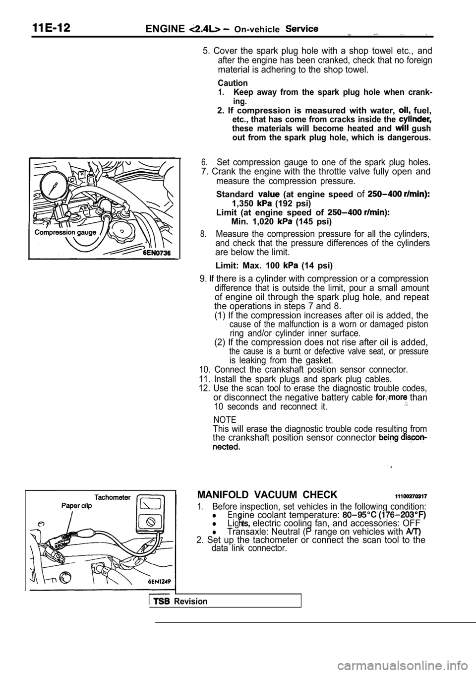
Caution
1.Keep away from the spark plug hole when crank-
ing.
2. If compression is measured with water, fuel,
etc., that has come from cracks inside the
these materials will become heated and gush
out from the spark plug hole, which is dangerous.
6.Set compression gauge to one of the spark plug hole s.
7. Crank the engine with the throttle valve fully open and
measure the compression pressure.
Standard (at engine speed of
1,350 (192 psi)
Limit (at engine speed of
Min. 1,020 (145 psi)
8.Measure the compression pressure for all the cylind ers,
and check that the pressure differences of the cyli nders
are below the limit.
Limit: Max. 100 (14 psi)
9. there is a cylinder with compression or a compression
difference that is outside the limit, pour a small amount
of engine oil through the spark plug hole, and repe at
the operations in steps 7 and 8.
(1) If the compression increases after oil is added , the
cause of the malfunction is a worn or damaged pisto n
ring and/or cylinder inner surface.
(2) If the compression does not rise after oil is added,
the cause is a burnt or defective valve seat, or pr essure
is leaking from the gasket.
10. Connect the crankshaft position sensor connecto r.
11. Install the spark plugs and spark plug cables.
12. Use the scan tool to erase the diagnostic troub le codes,
or disconnect the negative battery cable than
10 seconds and reconnect it.
NOTE
This will erase the diagnostic trouble code resulting from
the crankshaft position sensor connector
MANIFOLD VACUUM CHECK
1.Before inspection, set vehicles in the following co ndition:
lEn
lLig electric cooling fan, and accessories: OFF
ine coolant temperature:
lTransaxle: Neutral (P range on vehicles with
2. Set up the tachometer or connect the scan tool t o the
data link connector.
Revision
Page 284 of 2103
.
4 . 9 N m
\ / X L - -3.6
. .
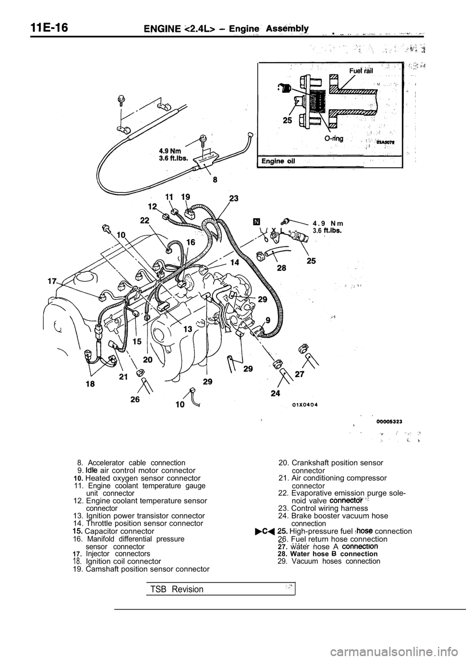
8. Accelerator cable connection9. air control motor connector
10. Heated oxygen sensor connector
11. Engine coolant temperature gauge
unit connector
12. Engine coolant temperature sensorconnector13. Ignition power transistor connector
14. Throttle position sensor connector
Capacitor connector16. Manifold differential pressure
20. Crankshaft position sensor
connector21. Air conditioning compressor
connector22. Evaporative emission purge sole-
noid valve
23. Control wiring harness
24. Brake booster vacuum hose
connection High-pressure fuel connection
26. Fuel return hose connection --
. .. .
17.18.
sensor connector
Injector connectors
Ignition coil connector
19. Camshaft position sensor connector 27.
water nose A 28. Water hose connection29. Vacuum hoses connection
TSB Revision
Page 289 of 2103
and Camshaft Seal
CAMSHAFT AND CAMSHAFT OIL SEAL
REMOVAL AND INSTALLATION
Pm-removal Operationl Battery RemovalPost-installationl Battery Installationl Engine Adjustment
7-9
Sealant:
MITSUBISHI GENUINE PART
or equivalent
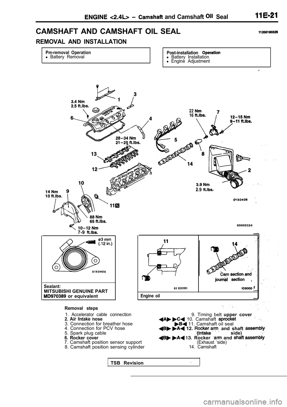
Removal steps
1. Accelerator cable connection . . . . . .2. Air Intake nose3. Connection for breather hose
4. Connection for PCV hose
5. Spark plug cable
6. Rocker cover7. Camshaft position sensor support
8. Camshaft position sensing cylinder
2216
2.9
00005324
Engine oil
,
01
9. Timing belt upper cover 10. Camshaft 11. Camshaft oil seal 12. and shaft side) Rocker and (Exhaust ‘side)
14. Camshaft
TSB Revision
Page 381 of 2103
FUEL
INJECTION
CONTENTS
FUEL INJECTION (MFI)
ENGINE (NON-TURBO)> . . . . . . . 3
Relay (ASD Relay) and Fuel ‘Relay
Check.. . . . . . . . . . . . . . . . . . . . . . . . . . , . . . . .128
Throttle Position Sensor Check. . . . . . . . . . .
129
GENERAL INFORMATION . . . . . . . . . . . . . . . . 3ON-VEHICLE SERVICE. . . . . . . . . . . . . . . .119
INJECTOR. . . . . . . . . . . . . . . . . . . . . . . . . . . .134Fuel Pressure Test . . . . . . . . . . . , . . . . . . . . .121
ON-VEHICLE INSPECTION OF
COMPONENTS . . . . . . . . . . . . . . . . . . . . . .
Component Location. . . . . . . . . . . . . . . . . . . 124
Electric EGR Transducer Solenoid Check
. . . . . . . . . . . . . . . . . . . . . . . . . . . . . . .. . . . . . . . .133
Engine Coolant Temperature Sensor Check
. . . . . . . . . . . . . . . . . . . . . . . . . . . . . . . . . . . . . . . .129
Evaporative Emission Purge Solenoid
C h e c k . . . . . . . . . . . . . . . . . . . . . . . . . . . . . . . . . . 1 3 3
Heated Oxygen Sensor Check . . . . . . . . . . . 13 0
Idle Air Control Motor (Stepper Motor)
Check . . . . . . . . . . . . . . . . . . . . . . . . . . . . . . . . . .132
Injector Check . . . . . . . . . . . . . . . . . . . . . . . . . .132
Intake Air Temperature Sensor Check . . . . 128 Fuel Pump Connector Disconnection
(How to Reduce Fuel Line Pressure) . . . . . 123
Throttle Body Minimum Air
Check . . . 110 ,
SEALANT. . . . . . . . . . . . . . . . . . . . . . . . . . . . . . .
SERVICE SPECIFICATIONS . . . . . . . . . . . . . . 6
SPECIAL TOOLS . . . . . . . . . . . . . . .
. . . . . 7,
THROTTLE BODY . . . . . . . . . . . . . . . . .
TROUBLESHOOTING. . . . . . . . . . . . . . . . 6
CONTINUED ON NEXT PAGE
Page 382 of 2103
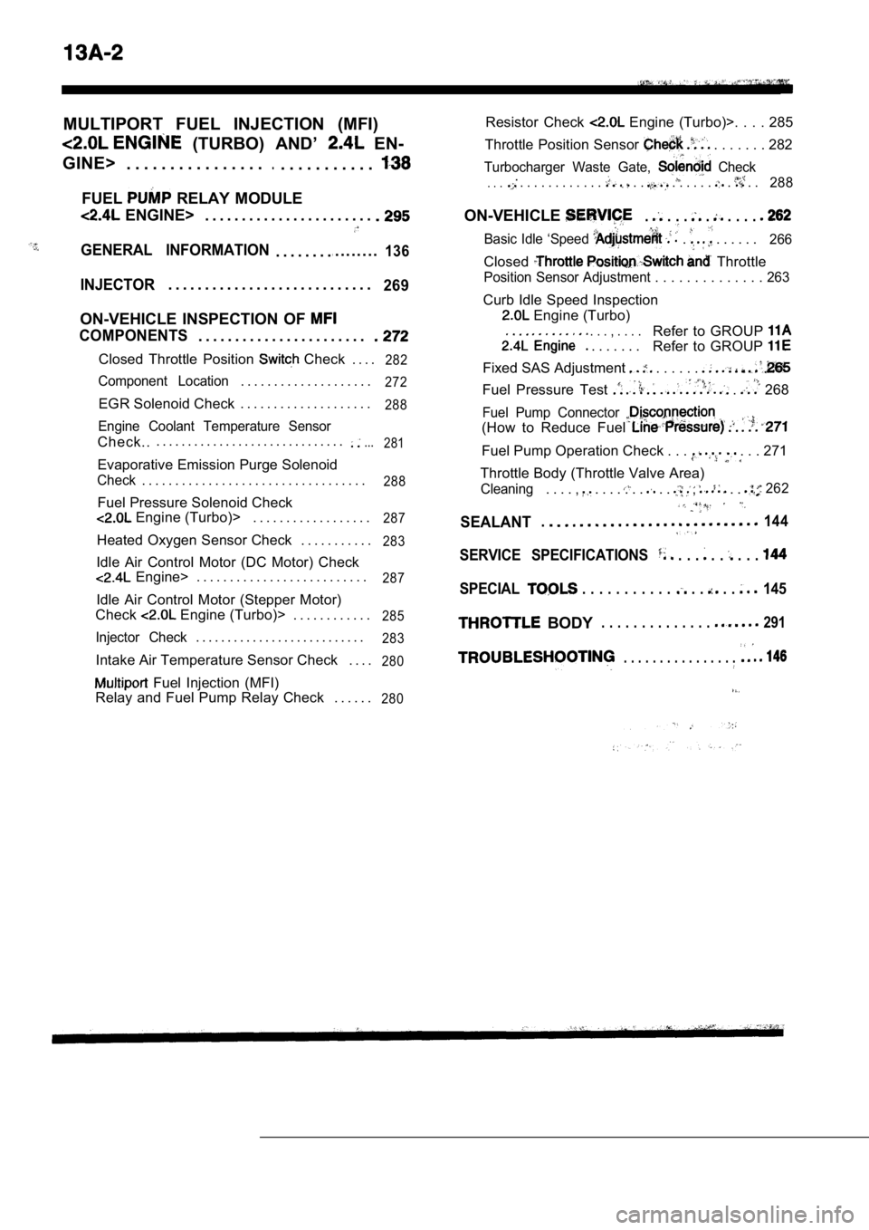
MULTIPORT FUEL INJECTION (MFI)
(TURBO) AND’ EN-
GINE> . . . . . . . . . . . . . . . .
.. . . . . . . . . . .
FUEL RELAY MODULE
ENGINE> . . . . . . . . . . . . . . . . . . . . . . .
GENERAL INFORMATION. . . . . . . ... . . . . . . .136
INJECTOR. . . . . . . . . . . . . . . . . . . . . . . . . . . .269
ON-VEHICLE INSPECTION OF
COMPONENTS. . . . . . . . . . . . . . . . . . . . . . .
Closed Throttle Position Check . . . .282
Component Location. . . . . . . . . . . . . . . . . . . .272
EGR Solenoid Check . . . . . . . . . . . . . . . . . . . .288
Engine Coolant Temperature Sensor
Check... . . . . . . . . . . . . . . . . . . . . . . . . . . . . ....
281
Evaporative Emission Purge Solenoid
Check. . . . . . . . . . . . . . . . . . . . . . . . . . . . . . . . . .288
Fuel Pressure Solenoid Check
Engine (Turbo)> . . . . . . . . . . . . . . . . . .287
Heated Oxygen Sensor Check . . . . . . . . . . .283
Idle Air Control Motor (DC Motor) Check
Engine> . . . . . . . . . . . . . . . . . . . . . . . . . .287
Idle Air Control Motor (Stepper Motor)
Check
Engine (Turbo)> . . . . . . . . . . . .285
Injector Check. . . . . . . . . . . . . . . . . . . . . . . . . . .283
Intake Air Temperature Sensor Check . . . .280
Fuel Injection (MFI)
Relay and Fuel Pump Relay Check . . . . . .
280
Resistor Check Engine (Turbo)>. . . . 285
Throttle Position Sensor
. . . . . . . 282
Turbocharger Waste Gate, Check.. . . . . . . . . . . . . . . . . . . . . . . . . .288
ON-VEHICLE. . . . . . . . .
Basic Idle ‘Speed . . . . . . . 266
Closed Throttle
Position Sensor Adjustment . . . . . . . . . . . . . . 263
Curb Idle Speed Inspection
Engine (Turbo)
. . . , . . . .
. . . . . . .
Refer to GROUP
Refer to GROUP
Fixed SAS Adjustment . . . . . .
Fuel Pressure Test . 268
Fuel Pump Connector
(How to Reduce Fuel
Fuel Pump Operation Check . . . . . . 271
Throttle Body (Throttle Valve Area)
Cleaning. . . . , . . . . . . . . . , . . 262
SEALANT.144
SERVICE SPECIFICATIONS . . . . . . . .
SPECIAL . . . . . . . . . . . . . . . 145
BODY. . . . . . . . . . . . . . 291
. . . . . . . . . . . . . . . .
Page 383 of 2103
ENGINE (NON-TURBO)> General
FUEL INJECTION
ENGINE (NON-TURBO)>
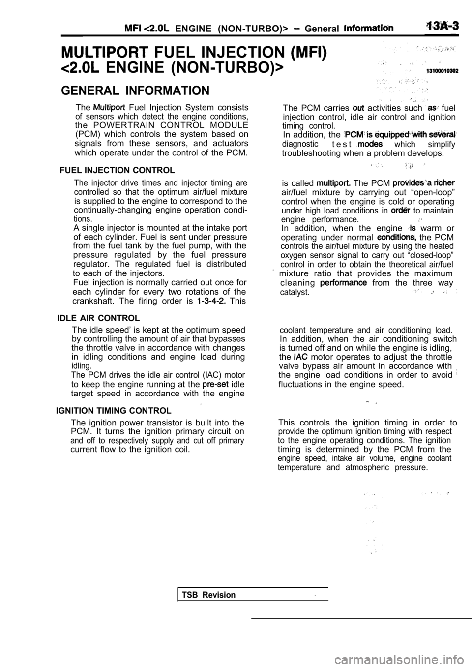
GENERAL INFORMATION
The Fuel Injection System consists
of sensors which detect the engine conditions,
the POWERTRAIN CONTROL MODULE(PCM) which controls the system based on
signals from these sensors, and actuators
which operate under the control of the PCM.
FUEL INJECTION CONTROL
The injector drive times and injector timing are
controlled so that the optimum air/fuel mixture
is supplied to the engine to correspond to the
continually-changing engine operation condi-
tions.
A single injector is mounted at the intake port
of each cylinder. Fuel is sent under pressure
from the fuel tank by the fuel pump, with the
pressure regulated by the fuel pressureregulator. The regulated fuel is distributed
to each of the injectors. Fuel injection is normally carried out once for
each cylinder for every two rotations of the
crankshaft. The firing order is
This
IDLE AIR CONTROL The idle speed’ is kept at the optimum speed
by controlling the amount of air that bypasses
the throttle valve in accordance with changes in idling conditions and engine load during
idling.
The PCM drives the idle air control (IAC) motor
to keep the engine running at the idle
target speed in accordance with the engine
IGNITION TIMING CONTROL
The ignition power transistor is built into the
PCM. It turns the ignition primary circuit on
and off to respectively supply and cut off primary
current flow to the ignition coil. The PCM carries
activities such fuel
injection control, idle air control and ignition
timing control.
In addition, the
diagnostict e s twhich simplify
troubleshooting when a problem develops.
is called The PCM
air/fuel mixture by carrying out “open-loop”
control when the engine is cold or operating
under high load conditions in to maintain
engine performance.
In addition, when the engine warm or
operating under normal
the PCM
controls the air/fuel mixture by using the heated
oxygen sensor signal to carry out “closed-loop”
control in order to obtain the theoretical air/fuel
mixture ratio that provides the maximum
cleaning
from the three way
catalyst.
coolant temperature and air conditioning load.
In addition, when the air conditioning switch
is turned off and on while the engine is idling,
the
motor operates to adjust the throttle
valve bypass air amount in accordance with
the engine load conditions in order to avoid
fluctuations in the engine speed.
This controls the ignition timing in order to
provide the optimum ignition timing with respect
to the engine operating conditions. The ignition
timing is determined by the PCM from the
engine speed, intake air volume, engine coolant
temperature and atmospheric pressure.
TSB Revision
Page 384 of 2103
ENGINE (NON-TURBO)>
DIAGNOSTIC TEST MODE
l When an abnormality is detected in one
of the sensors or actuators related to
emission control, the CHECK
MALFUNCTION INDICATOR LAMP
nates as a warning to the driver.
l When an abnormality is detected in one
of the sensors or actuators, a diagnostic
OTHER CONTROL FUNCTIONS
t r o u b l e c o d e
a b n o r m a l i t y i s o u t p u t .
lThe RAM data inside the PCM that is
to the sensors and
by means of the scan tool.
In addition, the actuators can be controlled
under certain circumstances. . ,
1. Fuel Pump Control
Turns the fuel pump relay ON so that current
is supplied to the fuel pump while the engine
is cranking or running.
2. A/C Compressor Clutch Relay Control Turns the A/C compressor clutch ON and
OFF.
3. Fan Relay Control
The radiator fan and condenser fan speeds
are controlled in response to the engine
coolant temperature and vehicle speed. 4. Generator
Controls the generator in order
to control the generated current.
5. Engine Speedometer or Tachometer
Control.
Sends a pulse signal which ‘corresponds
to the engine speed to the’ speedometer
unit..
6. Evaporative Emission Purge
C o n t r o l
Refer to GROUP 17.
7. Electric EGR Transducer Solenoid Control Refer to GROUP 17.
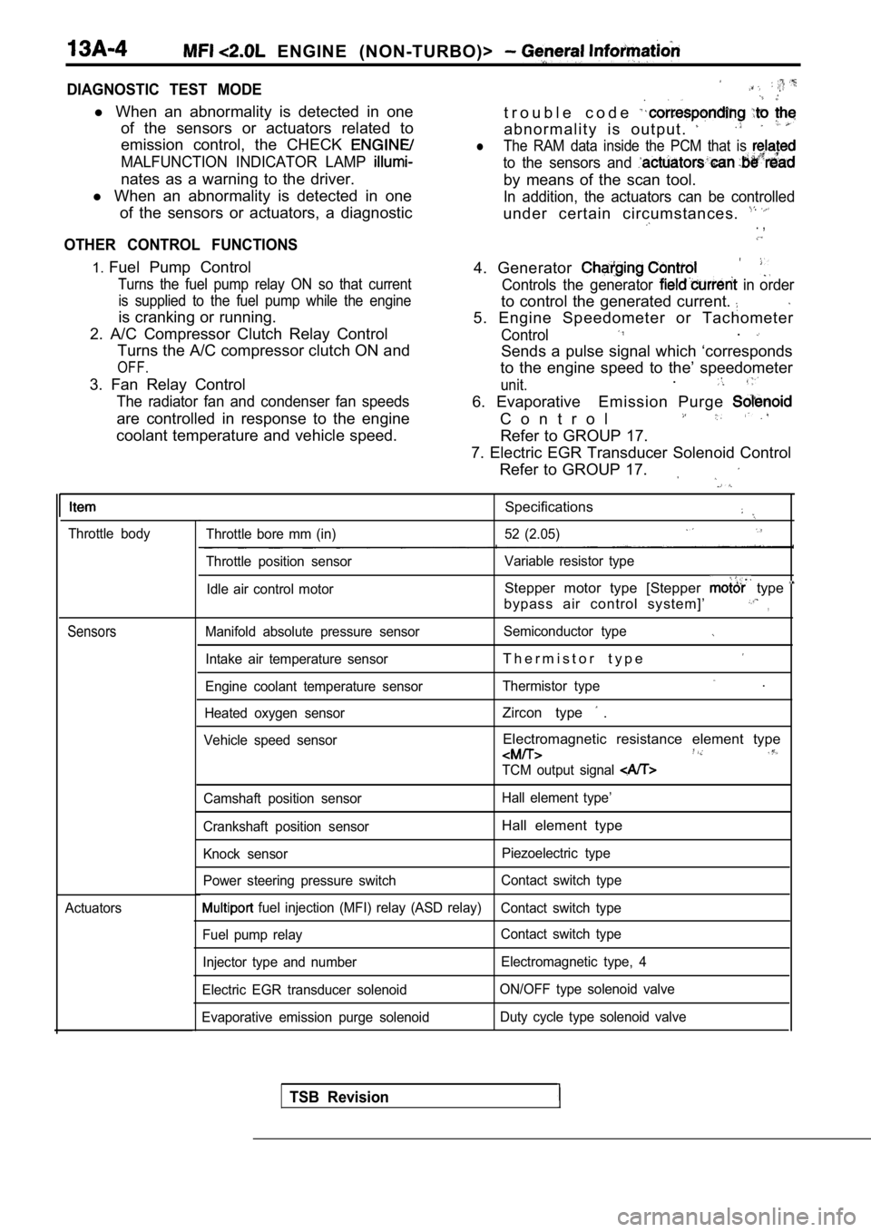
Throttle body
Sensors
Actuators
Specifications
Throttle bore mm (in) 52 (2.05)
Throttle position sensor Variable resistor type
Idle air control motor
Stepper motor type [Stepper type
bypass air control system]’,
Manifold absolute pressure sensor Semiconductor type
Intake air temperature sensorT h e r m i s t o r t y p e
Engine coolant temperature sensorThermistor type .
Heated oxygen sensorZircon type .
Vehicle speed sensorElectromagnetic resistance element type
TCM output signal
Camshaft position sensor Hall element type’
Crankshaft position sensor
Hall element type
Knock sensor Piezoelectric type
Power steering pressure switch Contact switch type
fuel injection (MFI) relay (ASD relay)
Contact switch type
Fuel pump relay Contact switch type
Injector type and number Electromagnetic type, 4
Electric EGR transducer solenoid ON/OFF type solenoid valve
Evaporative emission purge solenoid Duty cycle type solenoid valve
TSB Revision
Page 385 of 2103
ENGINE (NON-TURBO)>
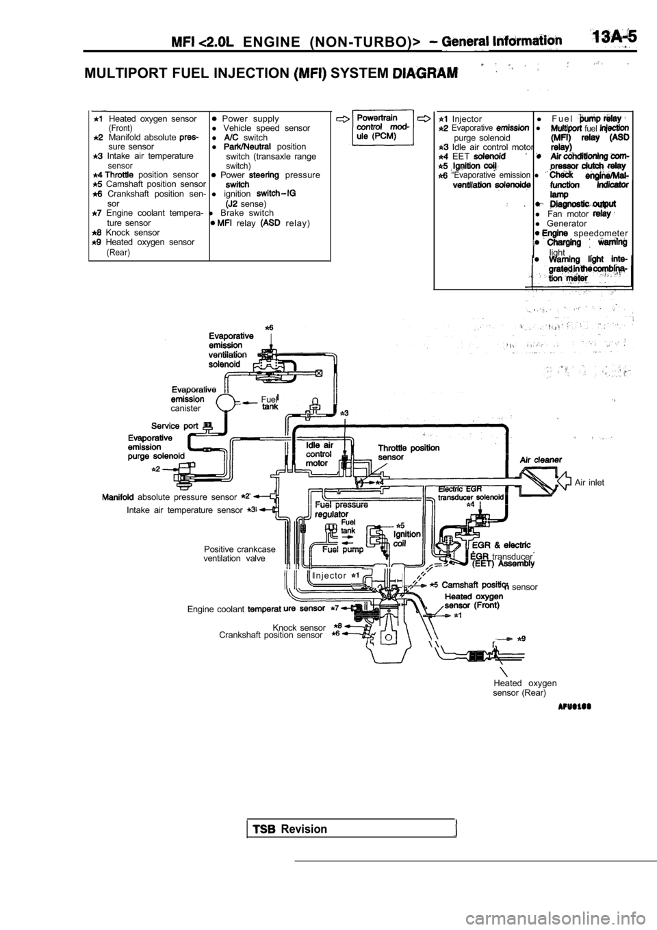
MULTIPORT FUEL INJECTION SYSTEM
Heated oxygen sensor Power supply(Front)l Vehicle speed sensor
Manifold absolute l switch
sure sensor l position Intake air temperature
switch (transaxle rangesensor switch) position sensor Power pressure Camshaft position sensor Crankshaft position sen- l ignitionsor sense) Engine coolant tempera- l Brake switch
ture sensor relay r e l a y ) Knock sensor Heated oxygen sensor(Rear)
Injector l
F u e l Evaporative l fuel purge solenoid Idle air control motor EET
“Evaporative emission l
.l Fan motor l Generator speedometer
light
.
Fuel
canister
absolute pressure sensor
Intake air temperature sensor
Positive crankcase
ventilation valve
I n j e c t o r
transducer
sensor
Engine coolant
Knock sensor
Crankshaft position sensor
Air inlet
Heated oxygen
sensor (Rear)
Revision