1990 MITSUBISHI SPYDER sensor
[x] Cancel search: sensorPage 386 of 2103
Service ENGINE (NON-TURBO)> Sealants
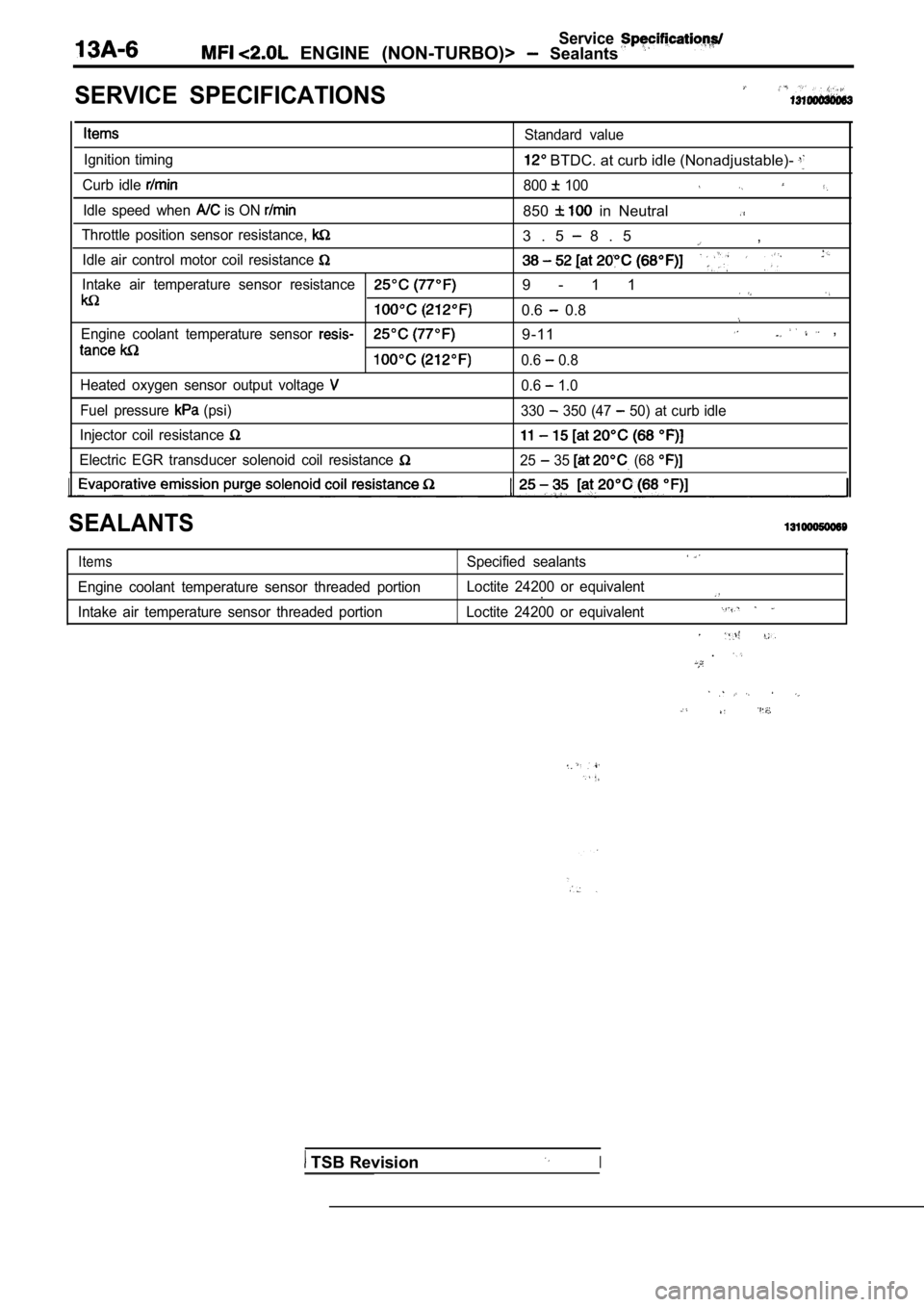
SERVICE SPECIFICATIONS
Ignition timing
Curb idle
Idle speed when is ON
Standard value
BTDC. at curb idle (Nonadjustable)-
800 100
850 in Neutral
Throttle position sensor resistance,
Idle air control motor coil resistance
Intake air temperature sensor resistance
Engine coolant temperature sensor
Heated oxygen sensor output voltage
Fuel pressure (psi)
Injector coil resistance
Electric EGR transducer solenoid coil resistance
3 . 5 8 . 5 ,
9 - 1 1
0.6 0.8
9-11 ,
0.6 0.8
0.6
1.0
330
350 (47 50) at curb idle
25 35 (68
SEALANTS
Items
Engine coolant temperature sensor threaded portion
Intake air temperature sensor threaded portion
,Specified sealants
Loctite 24200 or equivalent.
Loctite 24200 or equivalent
.
TSB RevisionI
Page 389 of 2103
ENGINE (NON-TURBO)>
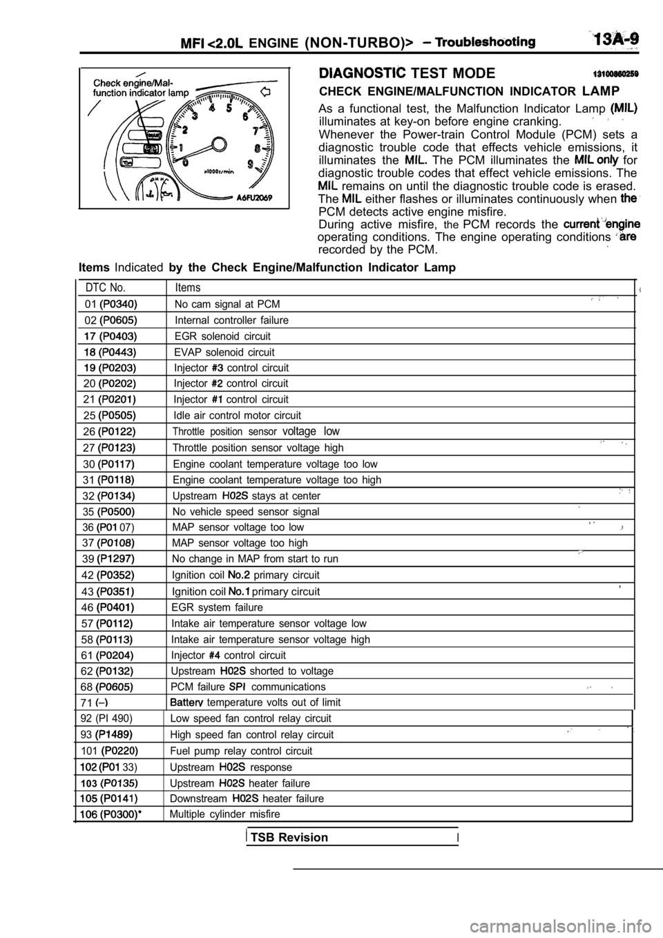
TEST MODE
CHECK ENGINE/MALFUNCTION INDICATOR LAMP
As a functional test, the Malfunction Indicator Lam p
illuminates at key-on before engine cranking.
Whenever the Power-train Control Module (PCM) sets a
diagnostic trouble code that effects vehicle emissi ons, it
illuminates the
The PCM illuminates the for
diagnostic trouble codes that effect vehicle emissi ons. The
remains on until the diagnostic trouble code is erased.
The
either flashes or illuminates continuously when
PCM detects active engine misfire.
During active misfire, thePCM records the
operating conditions. The engine operating conditio ns
recorded by the PCM.
ItemsIndicated by the Check Engine/Malfunction Indicator Lamp
DTC No. Items
01No cam signal at PCM
02Internal controller failure
EGR solenoid circuit
EVAP solenoid circuit
Injector control circuit
20Injector control circuit
21Injector control circuit
25Idle air control motor circuit
26Throttle position sensor voltage low
27Throttle position sensor voltage high
30Engine coolant temperature voltage too low
31Engine coolant temperature voltage too high
32Upstream stays at center
35
No vehicle speed sensor signal
36
07) MAP sensor voltage too low
37MAP sensor voltage too high
39No change in MAP from start to run
42Ignition coil primary circuit
43Ignition coil primary circuit
46
EGR system failure
57Intake air temperature sensor voltage low
58Intake air temperature sensor voltage high
61Injector control circuit
62Upstream shorted to voltage
68PCM failure communications
71 temperature volts out of limit
, .
,
92 (PI 490)
93
101
33)
103
Low speed fan control relay circuit
High speed fan control relay circuit
Fuel pump relay control circuit
Upstream
response
Upstream
heater failure
Downstream
heater failure
Multiple cylinder misfire
TSB RevisionI
Page 390 of 2103
ENGINE (NON-TURBO)> Troubleshooting
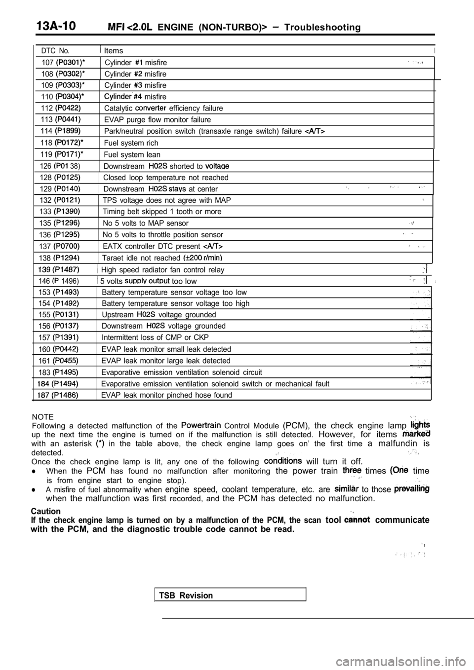
DTC No. ItemsI
107
108
109
110
112
113
114
118
119
126 38)
Cylinder misfire
Cylinder
misfire
Cylinder
misfire
misfire
Catalytic
efficiency failure
EVAP purge flow monitor failure
Park/neutral position switch (transaxle range switc h) failure
Fuel system rich
Fuel system lean
Downstream
shorted to
128Closed loop temperature not reached
129
Downstream at center
132
133
TPS voltage does not agree with MAP
Timing belt skipped 1 tooth or more
135No 5 volts to MAP sensor
136No 5 volts to throttle position sensor
137EATX controller DTC present
138Taraet idle not reached
High speed radiator fan control relay
146 1496)
153
154
155
156
157
160
161
183
5 volts too low
Battery temperature sensor voltage too low
Battery temperature sensor voltage too high
Upstream
voltage grounded
Downstream
voltage grounded
Intermittent loss of CMP or CKP
EVAP leak monitor small leak detected
EVAP leak monitor large leak detected
Evaporative emission ventilation solenoid circuit
Evaporative emission ventilation solenoid switch or mechanical fault
EVAP leak monitor pinched hose found
NOTE
Following a detected malfunction of the Control Module (PCM), the check engine lamp
up the next time the engine is turned on if the mal function is still detected. However, for items
with an asterisk in the table above, the check engine lamp goes on’ the first time a malfundin is
detected.
Once the check engine lamp is lit, any one of the f ollowing
will turn it off.
lWhen the PCMhas found no malfunction after monitoring the power train times time
is from engine start to engine stop).
lA misfire of fuel abnormality when engine speed, coolant temperature, etc. are to those
when the malfunction was first recorded, and the PCM has detected no malfunction.
Caution
If the check engine lamp is turned on by a malfunct ion of the PCM, the scan tool communicate
with the PCM, and the diagnostic trouble code canno t be read.
,
TSB Revision
Page 392 of 2103
ENGINE (NON-TURBO)> Troubleshooting.
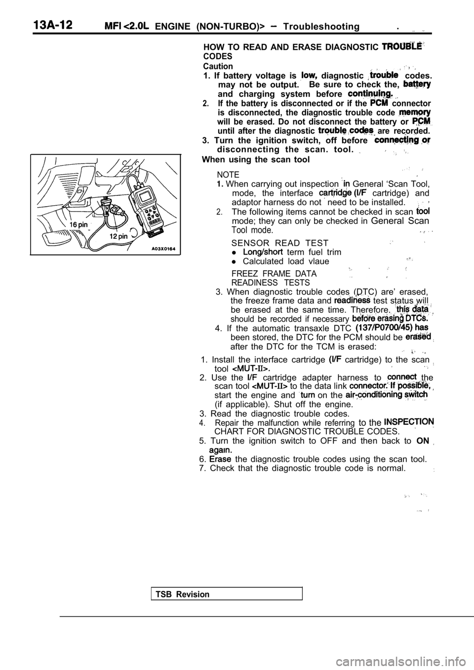
HOW TO READ AND ERASE DIAGNOSTIC
CODES
TSB Revision Caution
1. If battery voltage is diagnostic codes.
may not be output. Be sure to check the,
and charging system before
2.If the battery is disconnected or if the connector
is disconnected, the diagnostic trouble code
will be erased. Do not disconnect the battery or
until after the diagnostic are recorded.
3. Turn the ignition switch, off before
disconnecting the scan. tool.
When using the scan tool
NOTE
When carrying out inspection General ‘Scan Tool,
mode, the interface
cartridge) and
adaptor harness do not
need to be installed.
2.The following items cannot be checked in scan
mode; they can only be checked in General Scan
Tool mode.
SENSOR READ TEST
l term fuel trim
l Calculated load vlaue
FREEZ FRAME DATA
READINESS TESTS
3. When diagnostic trouble codes (DTC) are’ erased,
the freeze frame data and
test status will
be erased at the same time. Therefore,
should be recorded if necessary
4. If the automatic transaxle DTC
been stored, the DTC for the PCM should be
after the DTC for the TCM is erased:
1. Install the interface cartridge cartridge) to the scan
tool
2. Use the cartridge adapter harness to the
scan tool
to the data link
start the engine and on the
(if applicable). Shut off the engine.
3. Read the diagnostic trouble codes.
4.Repair the malfunction while referring to the
CHART FOR DIAGNOSTIC TROUBLE CODES.
5. Turn the ignition switch to OFF and then back to ON
6. the diagnostic trouble codes using the scan tool.
7. Check that the diagnostic trouble code is normal .
Page 395 of 2103
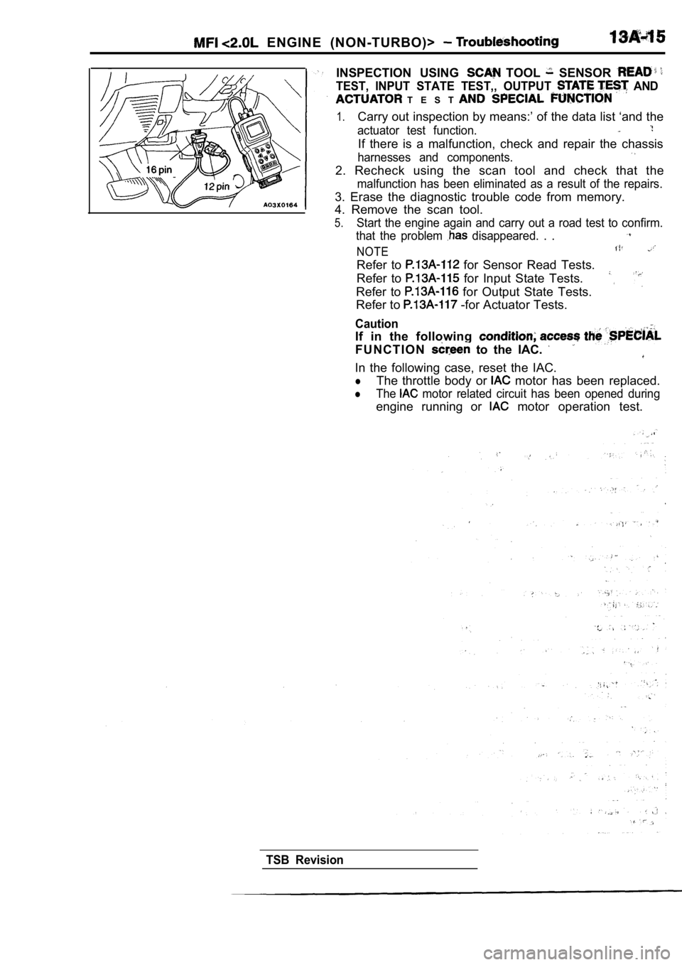
ENGINE (NON-TURBO)>
INSPECTION USING TOOL SENSOR
TEST, INPUT STATE TEST,, OUTPUT AND
T E S T
1.Carry out inspection by means:’ of the data list ‘and the
actuator test function.
If there is a malfunction, check and repair the cha ssis
harnesses and components.
2. Recheck using the scan tool and check that the
malfunction has been eliminated as a result of the repairs.
3. Erase the diagnostic trouble code from memory.
4. Remove the scan tool.
5.Start the engine again and carry out a road test to confirm.
that the problem
disappeared. . .
NOTE
Refer to for Sensor Read Tests.
Refer to
for Input State Tests.
Refer to
for Output State Tests.
Refer to -for Actuator Tests.
Caution
If in the following
F U N C T I O N to the IAC.
In the following case, reset the IAC.
lThe throttle body or motor has been replaced.
lThe motor related circuit has been opened during
engine running or motor operation test.
TSB Revision
Page 396 of 2103
ENGINE (NON-TURBO)> Troubleshooting
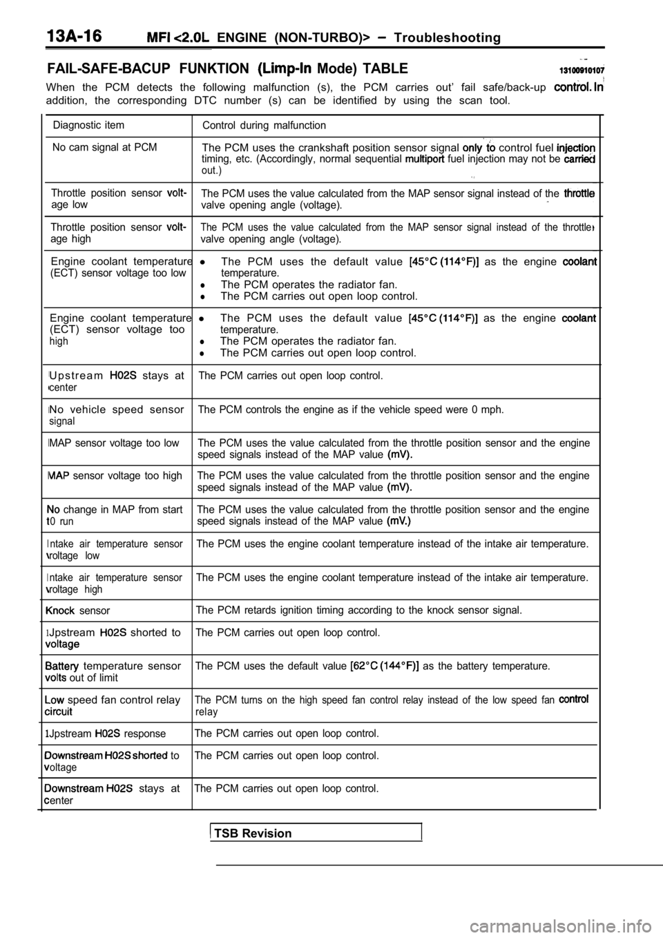
FAIL-SAFE-BACUP FUNKTION Mode) TABLE
When the PCM detects the following malfunction (s), the PCM carries out’ fail safe/back-up
addition, the corresponding DTC number (s) can be i dentified by using the scan tool.
I
I
I
I
I
1
1
Diagnostic item
Control during malfunction
No cam signal at PCM
The PCM uses the crankshaft position sensor signal control fuel timing, etc. (Accordingly, normal sequential fuel injection may not be
out.)
Throttle position sensor The PCM uses the value calculated from the MAP sens or signal instead of the age low
valve opening angle (voltage).
Throttle position sensor The PCM uses the value calculated from the MAP sens or signal instead of the throttle
age high
valve opening angle (voltage).
Engine coolant temperature l
The PCM uses the default value as the engine
(ECT) sensor voltage too low temperature.
lThe PCM operates the radiator fan.
lThe PCM carries out open loop control.
Engine coolant temperature lThe PCM uses the default value
as the engine
(ECT) sensor voltage tootemperature.
highlThe PCM operates the radiator fan.
lThe PCM carries out open loop control.
U p s t r e a m
stays atThe PCM carries out open loop control.
center
No vehicle speed sensorThe PCM controls the engine as if the vehicle speed were 0 mph.
signal
MAP sensor voltage too low The PCM uses the value ca lculated from the throttle position sensor and the engine
speed signals instead of the MAP value
sensor voltage too high The PCM uses the value calc ulated from the throttle position sensor and the engine
speed signals instead of the MAP value
change in MAP from start The PCM uses the value cal culated from the throttle position sensor and the engine
0 runspeed signals instead of the MAP value
ntake air temperature sensorThe PCM uses the engine coolant temperature instead of the intake air temperature.
roltage low
ntake air temperature sensor
The PCM uses the engine coolant temperature instead of the intake air temperature.
roltage high
sensorThe PCM retards ignition timing according to the kn
ock sensor signal.
Jpstream shorted toThe PCM carries out open loop control.
temperature sensorThe PCM uses the default value as the battery temperature.
out of limit
speed fan control relayThe PCM turns on the high speed fan control relay i nstead of the low speed fan
relay
Jpstream responseThe PCM carries out open loop control.
to The PCM carries out open loop control.
oltage
stays atThe PCM carries out open loop control.
enter
TSB Revision
Page 397 of 2103
ENGINE (NON-TURBO)> Troubleshooting
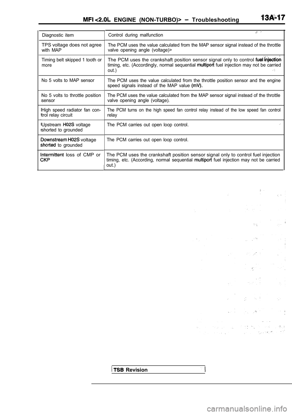
Diagnostic item
TPS voltage does not agree
with MAP
Timing belt skipped 1 tooth or
more
No 5 volts to MAP sensor
No 5 volts to throttle position
sensor
High speed radiator fan con-
trol relay circuit
Upstream
voltage
shorted to grounded
voltage
to grounded
loss of CMP or
Control during malfunction
The PCM uses the value calculated from the MAP sens or signal instead of the throttle
valve opening angle (voltage)>
The PCM uses the crankshaft position sensor signal only to control
timing, etc. (Accordingly, normal sequential fuel injection may not be carried
out.)
The PCM uses the value calculated from the throttle position sensor and the engine
speed signals instead of the MAP value
The PCM uses the value calculated from the MAP sens or signal instead of the throttle
valve opening angle (voltage).
The PCM turns on the high speed fan control relay i nstead of the low speed fan control
relay
The PCM carries out open loop control.
The PCM carries out open loop control.
The PCM uses the crankshaft position sensor signal only to control fuel injection
timing, etc. (According, normal sequential fuel injection may not be carried
out.)
Revision
Page 398 of 2103
ENGINE (NON-TURBO)> Troubleshooting
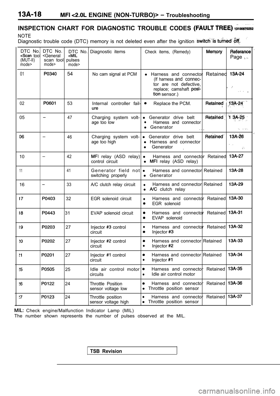
INSPECTION CHART FOR DIAGNOSTIC TROUBLE CODES
NOTE
Diagnostic trouble code (DTC) memory is not deleted even after the ignition
DTC No. DTC No.
DTC No. Diagnostic itemsCheck items, (Remedy) tool
mode>
mode>
01 54No cam signal at PCMl Harness and connector Retained
(If harness and connec-
tor are not defective,
replace; camshaft ,
sensor.) ,
02 53
Internal controller fail- Replace the PCM.,
. .
0547
46
Charging system volt- l Generator drive belt
age too lowlHarness and connector
l Generator. . ,
Charging system volt- l Generator drive belt
age too highl Harness and connector
l Generator
1042
1 141
1633
relay (ASD relay) lHarness and connector Retained
control circuitl relay (ASD relay)
G e n e r a t o r f i e l d n o t lHarness and connector Retained
switching properlyl Generator
A/C clutch relay circuitlHarness and connector Retained
l clutch relay
32
31
27
27
27
25
24
24
EGR solenoid circuitlHarness and connector Retained
EGR solenoid
EVAP solenoid circuit
Harness and connector Retained
EVAP solenoid
Injector
controllHarness and connector Retained
circuitInjector
Injector controlHarness and connector Retained
circuitlInjector
Injector controlHarness and connector Retained
circuitlInjector
Idle air control motor Harness and connector Retained
circuitslIdle air control motor
Throttle PositionHarness and connector Retained
sensor voltage lowl Throttle position sensor
Throttle positionlHarness and connector Retained
sensor voltage highl Throttle position sensor
TSB Revision
Check engine/Malfunction Indicator Lamp (MIL)
The number shown represents the number of pulses ob served at the MIL.