Page 220 of 2103
ENGINE OVERHAUL
.
INSTALLATION
(1) Install crankshaft position sensor.
Target
alignment
(2) The target magnet has locating dowels that fit into off-set
machined locating holes in end of the camshaft. ins tall
target magnet in end of camshaft. Tighten mounting
screw to 3 Nm (2.2
torque.
(3) Install camshaft position sensor. Tighten senso r mounting
screws to 9 Nm (6.5 torque.
(4) To avoid cross threading,
the spark plug into the
cylinder head by hand.
(5) Tighten spark plugs to 28 Nm (20
torque.
(6) Install spark plug insulators over spark plugs. Ensure
the top of the spark plug insulator seals the upper end
of the spark plug tube.
(7) Install ignition coil pack. Connect spark plug cables to coil pack.
The coil pack towers are numbered with the cylinder
identification.
Revision
Page 227 of 2103
ENGINE OVERHAUL Cooling System
COOLING SYSTEM COMPONENTS
REMOVAL
(1) Remove water pump attaching screws to engine.
Thermostat
Thermostat Gasket
(2) Remove level gauge.
(3) Remove exhaust manifold cover.
(4) Remove water hose.
(5) Remove water pipe.
(6) Remove O-ring.
(7) Remove thermostat housing bolts and housing.
(8)Remove thermostat, discard gasket and clean both ga sket
sealing surfaces.
(9) Remove engine coolant temperature sensor.
Remove switch.
TSB Revision
Page 228 of 2103

11 ENGINE OVERHAUL Cooling System
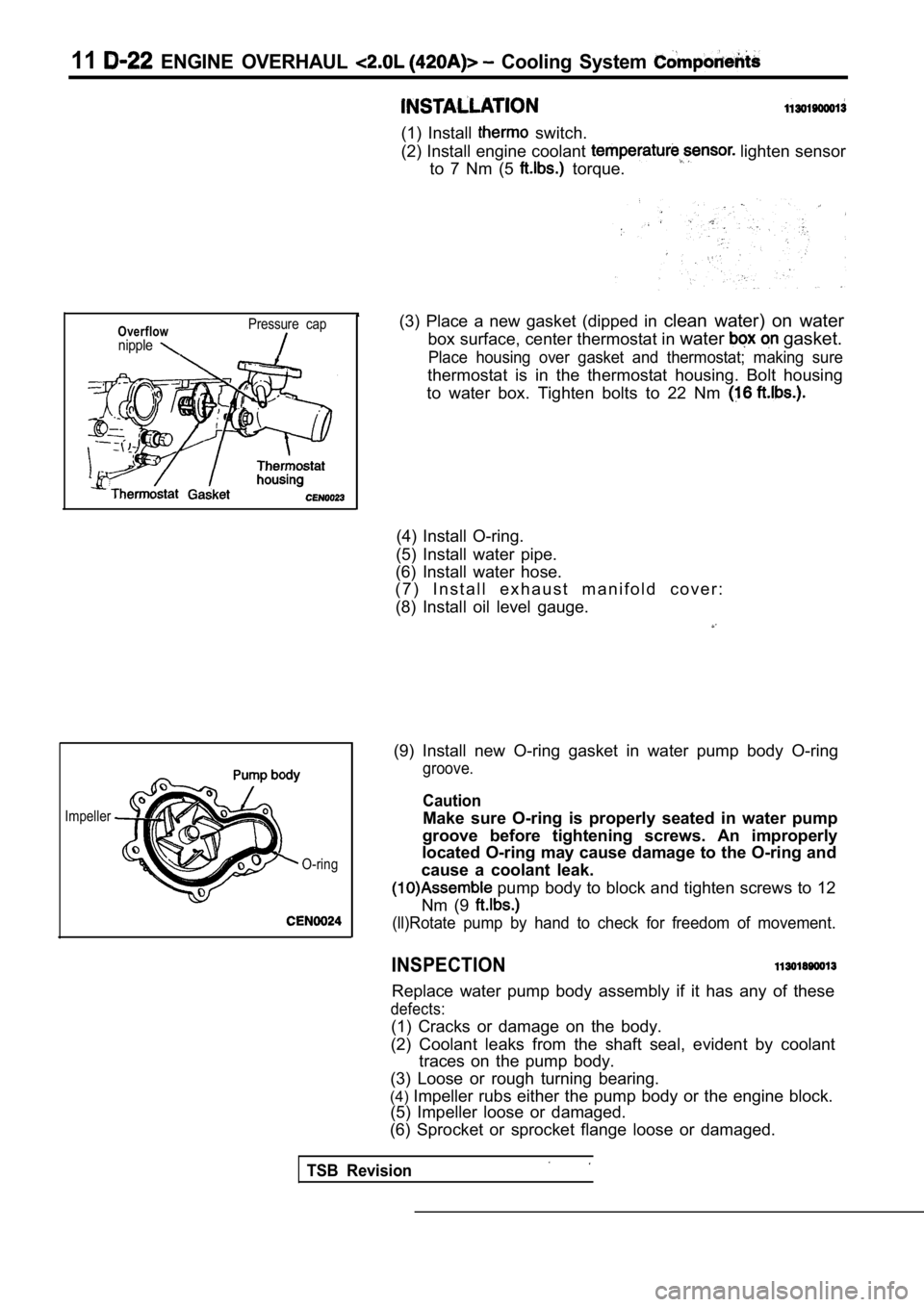
(1) Install switch.
(2) Install engine coolant
lighten sensor
to 7 Nm (5
torque.
Overflownipple
Pressure cap
Impeller
TSB Revision
O-ring
(3) Place a new gasket (dipped in clean water) on water
box surface, center thermostat in water
gasket.
Place housing over gasket and thermostat; making su re
thermostat is in the thermostat housing. Bolt housing
to water box. Tighten bolts to 22 Nm
(4) Install O-ring.
(5) Install water pipe.
(6) Install water hose.
( 7 ) I n s t a l l e x h a u s t m a n i f o l d c o v e r :
(8) Install oil level gauge.
(9) Install new O-ring gasket in water pump body O- ring
groove.
Caution
Make sure O-ring is properly seated in water pump
groove before tightening screws. An improperly
located O-ring may cause damage to the O-ring and
cause a coolant leak.
pump body to block and tighten screws to 12
Nm (9
(ll)Rotate pump by hand to check for freedom of mov ement.
INSPECTION
Replace water pump body assembly if it has any of these
defects:
(1) Cracks or damage on the body.
(2) Coolant leaks from the shaft seal, evident by c oolant
traces on the pump body.
(3) Loose or rough turning bearing.
(4) Impeller rubs either the pump body or the engine bl ock.
(5) Impeller loose or damaged.
(6) Sprocket or sprocket flange loose or damaged.
Page 231 of 2103
ENGINE OVERHAUL Manifold
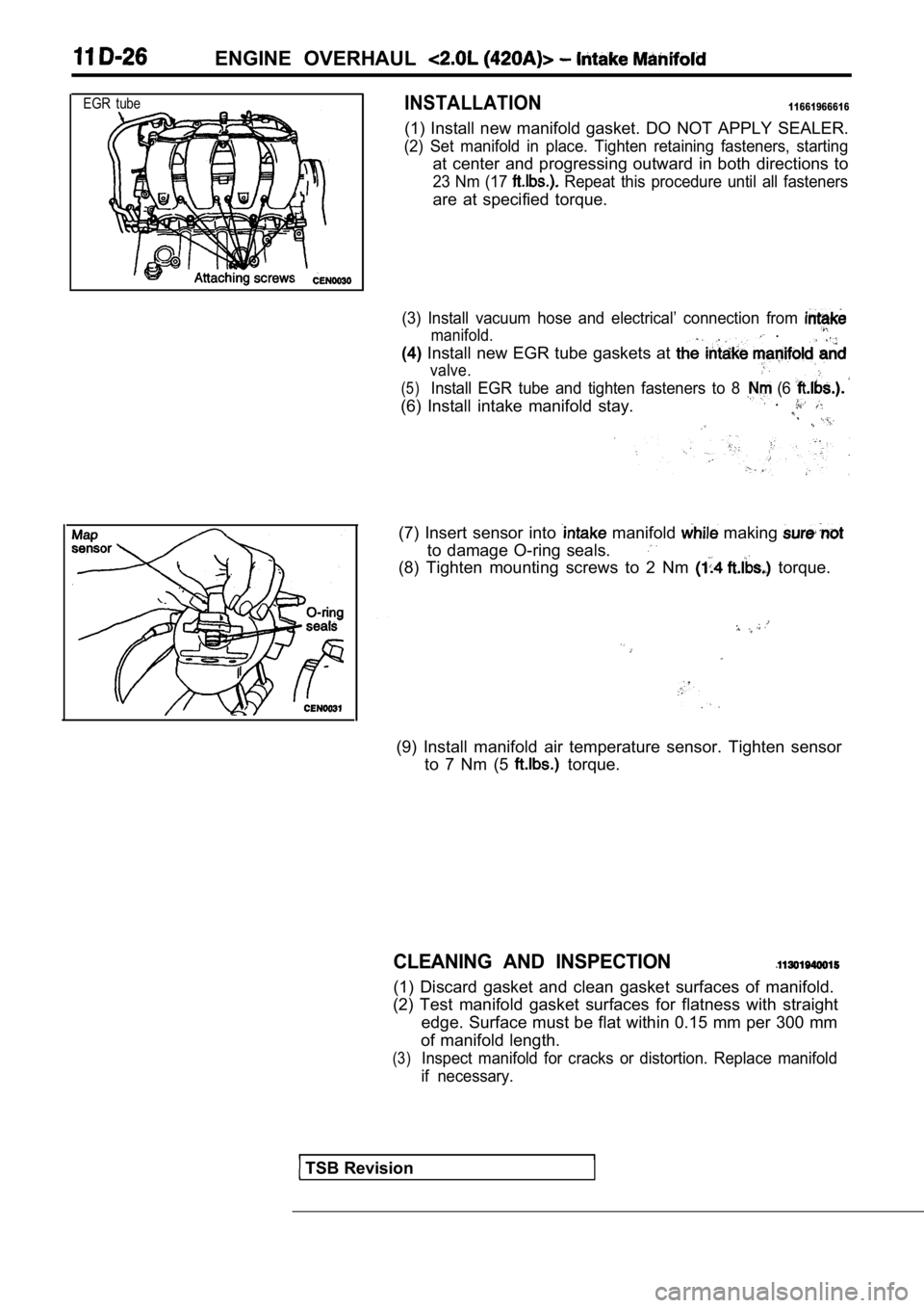
EGR tube
INTAKE MANIFOLD
(1) Remove intake air temperature sensor.
(2) Remove manifold absolute pressure (MAP) sensor mount-
ing screws.
(3) Remove manifold absolute pressure (MAP) sensor.
(4) Remove intake manifold stay.
(5) Remove EGR tube fasteners from the
and valve. Remove tube from engine.
Remove vacuum hose and electrical connection from in-
take manifold.
(7) Remove attaching
engine and remove intake
manifold from engine.
I .
TSB Revision
Page 232 of 2103

ENGINE OVERHAUL
EGR tubeINSTALLATION11661966616
(1) Install new manifold gasket. DO NOT APPLY SEALER.
(2) Set manifold in place. Tighten retaining fasteners, starting
at center and progressing outward in both direction s to
23 Nm (17 Repeat this procedure until all fasteners
are at specified torque.
(3) Install vacuum hose and electrical’ connection from
manifold. .
(4) Install new EGR tube gaskets at
valve.
(5)Install EGR tube and tighten fasteners to 8 (6
(6) Install intake manifold stay. .
(7) Insert sensor into manifold making
to damage O-ring seals.
(8) Tighten mounting screws to 2 Nm torque.
(9) Install manifold air temperature sensor. Tighte
n sensor
to 7 Nm (5
torque.
CLEANING AND INSPECTION
(1) Discard gasket and clean gasket surfaces of man ifold.
(2) Test manifold gasket surfaces for flatness with straight
edge. Surface must be flat within 0.15 mm per 300 m m
of manifold length.
(3)Inspect manifold for cracks or distortion. Replace manifold
if necessary.
TSB Revision
Page 261 of 2103
OVERHAUL
CRANKSHAFT
REMOVAL
Procedures after removing crankshaft sprocket, oil pan, pis-
tons and connecting rods.
(1) Using Tool remove front crankshaft oil seal.
Be careful not to damage the seal surface of cover.
(2) out rear seal with screwdriver. Becareful not to nick
or damage crankshaft flange seal surface or retaine r bore.
(3) Remove main bearing cap
(4) Remove bearing lower.
(5) Remove crankshaft.
(6) Remove bearing upper.
(7) Remove knock sensor.
(8) Remove oil pressure switch.
(9) Remove oil level gauge (dipstick).
Revision
Page 262 of 2103
ENGINE Crankshaft
Oil holes
I N S T A L L A T I O N
(1) Install oil level gauge (dipstick).
(2) Install oil pressure switch.
,
,
(3) Install knock sensor. Tighten knock sensor to 10 Nm
(7 torque. Over or under tightening effects knock
sensor performance, possibly causing improper spark con-
t r o l .
(4) Select proper thickness main bearing shells by referring
to CRANKSHAFT BEARING CLEARANCE.
NOTE
Upper and lower No. 3 bearing halves are flanged to
carry the crankshaft thrust loads and are NOT inter change-
able with any other bearing halves in the engine. Bearing
shells are available in standard and the following under-
sized:
0.016 mm, 0.032 mm, 0.250 mm.
Never install an undersize bearing that will reduce clear-
ance below specifications.
(5) Install the main bearing shells with the lubric ation groove
in the cylinder block.
TSB Revision
Page 279 of 2103

On-vehicle
Run the engine.
8. Set CO, HC tester.
7. Check the CO contents and the HC contents at idle.
Standard value:
CO contents: 0.5% or less
HC contents: 100 ppm or less
8. the standard value is exceeded, check the following
items:
l Diagnostic output
l Closed-loop control (When the closed-loop control
is carried out normally, the output signal of the heated
oxygen sensor and
at idle.)
l
Injector
lIgnition coil, spark plug
l system the
l Evaporative emission
Compression ,
NOTE,
Replace the three-way CO and
HC contents do not
the value.
(even though the
of the” on
all items.)
PRESSURE CHECK
1.Before inspection, check that the engine oil, start er and
battery are normal. Also, set the vehicle to the fo llowing
condition:
lEngine coolant temperature:
lLights, electric cooling fan and all accessories: O FF
lTransaxle: Neutral (P range on vehicles with
2. Disconnect the spark plug cables.
3. Remove all of the spark plugs.
4. Disconnect the crankshaft position sensor
NOTE
Doing this will prevent the engine control unit fro m carrying
out ignition and fuel injection.
TSB Revision