Page 1515 of 2103

FRONT AXLE Drive Shaft
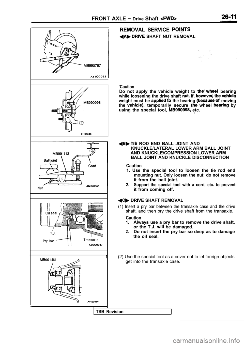
Nut
Pry bar Transaxle
1 461
I
REMOVAL SERVICE
SHAFT NUT REMOVAL
‘Caution
Do not apply the vehicle weight to bearing
while loosening the drive shaft If,
weight must be the bearing moving
the temporarily secure wheel by
using the special tool,
etc.
ROD END BALL JOINT AND
KNUCKLE/LATERAL LOWER ARM BALL JOINT
AND KNUCKLE/COMPRESSION LOWER ARM
BALL JOINT AND KNUCKLE DISCONNECTION
Caution
1. Use the special tool to loosen the tie rod end
mounting nut. Only loosen the nut; do not remove
it from the ball joint.
2.Support the special tool with a cord, etc. to preve nt
it from coming off.
DRIVE SHAFT REMOVAL
(1) Insert a pry bar between the transaxle case and the drive
shaft, and then pry the drive shaft from the transaxle.
Caution
1.Always use a pry bar to remove the drive shaft,
or the T.J.
be damaged.
2.Do not insert the pry bar so deep as to damage
the oil seal.
(2) Use the special tool as a cover not to let fore ign objects
get into the transaxle case.
TSB Revision
Page 1524 of 2103

FRONT AXLE Drive Shaft
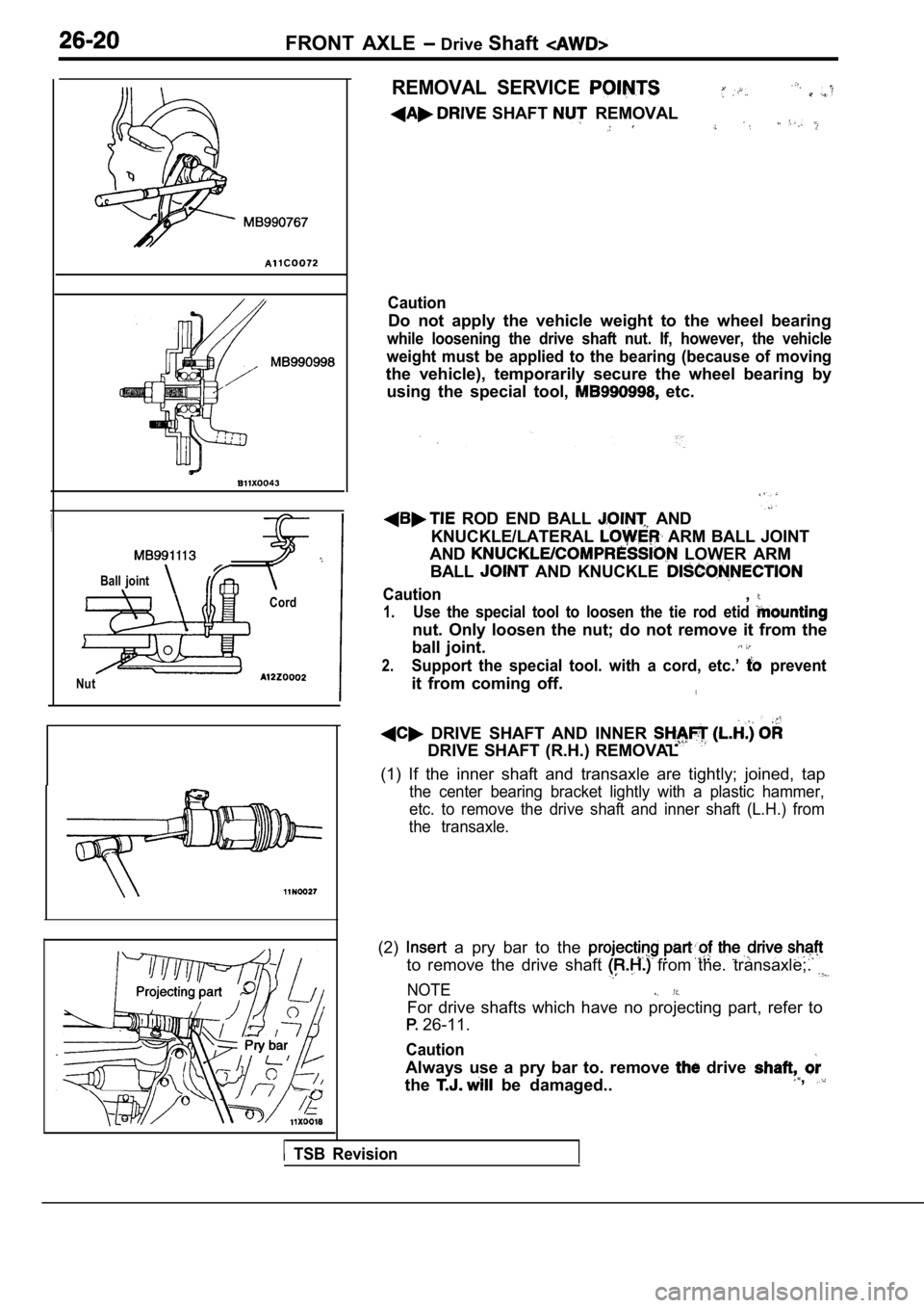
Ball joint
Cord
Nut
REMOVAL SERVICE
SHAFT REMOVAL
Caution
Do not apply the vehicle weight to the wheel bearin g
while loosening the drive shaft nut. If, however, the vehicle
weight must be applied to the bearing (because of m oving
the vehicle), temporarily secure the wheel bearing by
using the special tool,
etc.
ROD END BALL AND
KNUCKLE/LATERAL
ARM BALL JOINT
AND
LOWER ARM
BALL
AND KNUCKLE
Caution,
1.Use the special tool to loosen the tie rod etid
nut. Only loosen the nut; do not remove it from the
ball joint.
2.Support the special tool. with a cord, etc.’ prevent
it from coming off.
DRIVE SHAFT AND INNER
DRIVE SHAFT (R.H.) REMOVAL
(1) If the inner shaft and transaxle are tightly; j oined, tap
the center bearing bracket lightly with a plastic h ammer,
etc. to remove the drive shaft and inner shaft (L.H .) from
the transaxle.
(2) a pry bar to the
to remove the drive shaft from the. transaxle;.
NOTE
For drive shafts which have no projecting part, ref er to
26-11.
Caution
Always use a pry bar to. remove drive
the
be damaged..,
TSB Revision
Page 1594 of 2103
32-4P O W E R P L A N T M O U N T
REMOVAL AND INSTALLATION
OperationJack Up the Engine and Transaxle Assembly Until Thereis no Weight on the Engine Mount Bracket Insulator.
Engine (Non-turbo)>
86
63
9871
Removal steps
1. Enaine mount insulator mounting
2. Engine mount bracket 3. Engine mount stopper
Engine sideEngine
mount Engine
mount
stopper
______ .bracket
Engine (Turbo) and Engine>
87 .
,
9871 85
INSTALLATION POINT
ENGINE MOUNT
Align the notches on the stopper with the engine bracket
with the arrow mark facing toward the shown
install the stopper.
,
INSPECTION
lCheck each insulator for cracks or damage.
lCheck each bracket for deformations or damage.
TSB Revision
Page 1598 of 2103
32-8POWER PLANT MOUNT Engine Roll. Stopper,
(1) Set the special tool to the to the engine
assembly.
(2) Remove the centermember assembly.
INSTALLATION POINT
FRONT
If the dimension shown in the illustration the standard
value when the weight of the engine is the body, replace
the front roll stopper bracket
Standard value (A):
I.
INSPECTION
l each insulator for cracks damage.
l Check each bracket for
damage.
,
.
,
,
Revision