Page 1109 of 2103
AUTOMATIC TRANSAXLE , . . ,
ENGINE (TURBO) AND ENGINE> Transaxle Assembly
33
45-52Nm
33-38
2 5
From under vehicles
22. Tie rod end ball joint and knuckle
connection23. Stabilizer link connection
24. Damper fork
25. Lateral lower arm ball joint and
knuckle connection26. Compression lower arm ball jointand knuckle connection 27. Drive shaft connection 28. Bell housing cover
29. Stay (R.H.)
30. Centermember assembly
69-78 Nm
,
31. plate bolts
32. mounting bolts
33. bracket
34. Transaxle assembly
Cautionindicates parts should be temporarily tightened,
and then fully tightened the on the groundin the unladen condition. For tightening locations by the symbol, firsttighten temporarily, and then make the final with the entire weight of the engine applied to the body.
TSBRevision
Page 1111 of 2103
, , AUTOMATIC TRANSAXLE
ENGINE (TURBO) AND ENGINE> Transaxle Assembly
29-34 Nm
9.8-13 Nm
7.2-9.4
8.8Nm6.5
Nm
From under vehicles
18. Tie rod end ball
and knuckleconnection19. Stabilizer link connection
20. Damper fork
21. Lateral lower arm ball joint and
knuckle connection22. Compression lower arm ball jointand knuckle connection
23. Drive shaft connection 24. Bell housing cover
25. Stay (R.H.)
26. Centermember assembly
27. Drive connecting bolts28. Transaxle assembly mounting bolts29. Transaxle mounting
30. Transaxle assembly
Cautionl 1 The fasteners marked* should be htened
before they are finally tightened once the of the engine has been placed body.l 2:For tightening locations indicated by the symbol, f irst
tighten temporarily, and then make the
with the entire weight of the engineapplied totheve hicle
body.
Page 1113 of 2103
AUTOMATIC TRANSAXLE . .
ENGINE (TURBO) AND ENGINE> Assembly
Front roll
stopper
bracket
ber
DRIVE PLATE
(1)Use a transmisslon jack to the ,,Caution
Support the transaxle
(2) Remove the connection bolts while turning
(3) Press the torque converter into the transaxle f or easier
removal.
(4) Remove the transaxle assembly mounting bolt and lower
the transaxle assembly.
,
SERVICE
TRANSAXLE ASSEMBLY
After securely inserting the torque converter the transaxle
so that the
shown in the becomes the refer-
ence value, install the assembly the engine.
value (A):
m m
12.0
ASSEMBLY
If the dimension shown in the is outside the standard
value when the weight of the engine the body, replace
the front roll stopper bracket assembly.
Standard value (A):
mm
D R I V E S H A F T
Temporarily install the drive shaft so that T.J. case of
the drive shaft is perpendicular to the
Caution
Do not damage the oil by part of the
drive shaft.
Transaxle
TSB Revision
Page 1116 of 2103

.AUTOMATIC TRANSAXLE
ENGINE (TURBO) AND ENGINE> Transaxle Assembly
,
Cord
N i t
TSB Revision
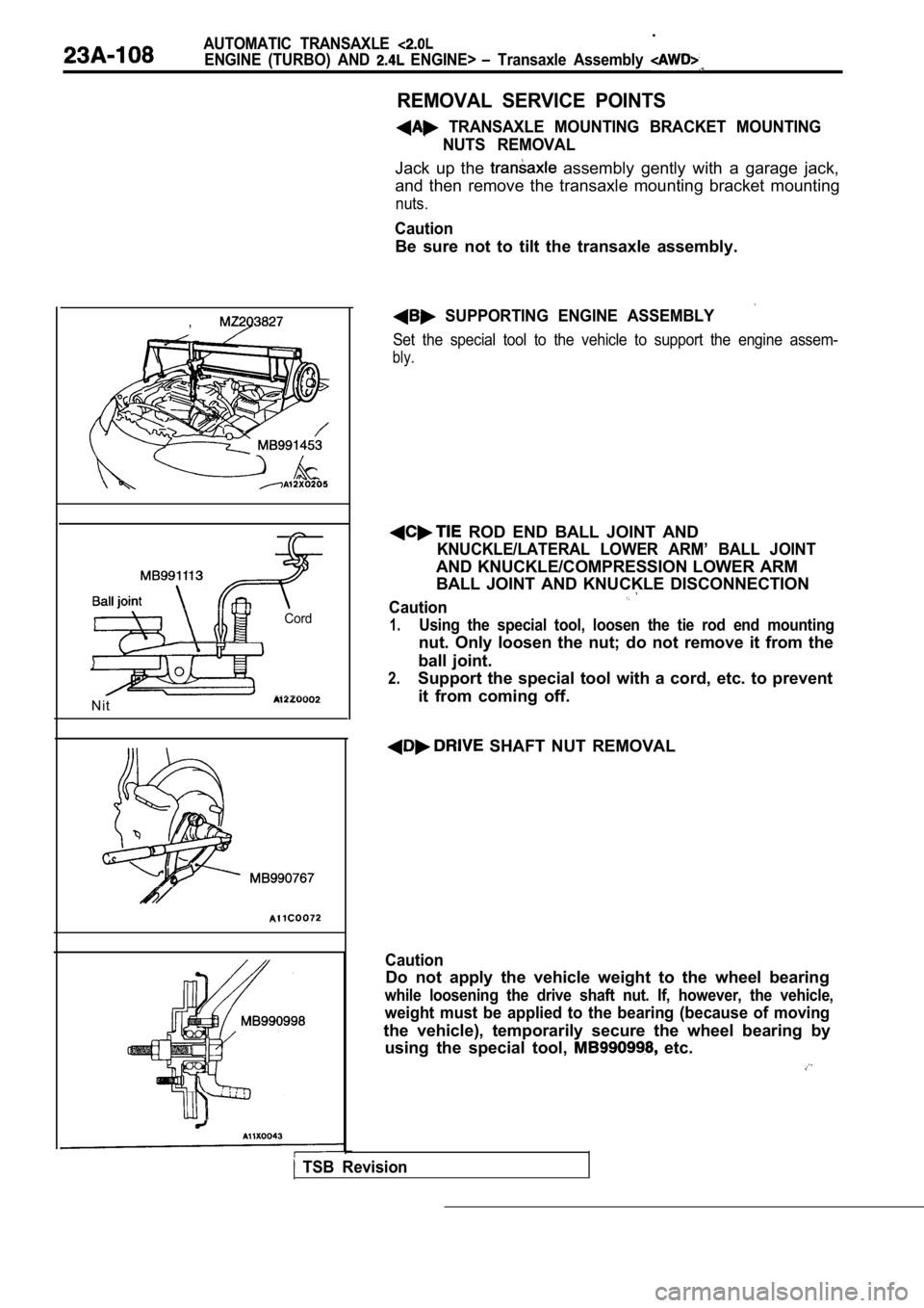
REMOVAL SERVICE POINTS
TRANSAXLE MOUNTING BRACKET MOUNTINGNUTS REMOVAL
Jack up the assembly gently with a garage jack,
and then remove the transaxle mounting bracket moun ting
nuts.
Caution
Be sure not to tilt the transaxle assembly.
SUPPORTING ENGINE ASSEMBLY
Set the special tool to the vehicle to support the engine assem-
bly.
ROD END BALL JOINT AND
KNUCKLE/LATERAL LOWER ARM’ BALL JOINT
AND KNUCKLE/COMPRESSION LOWER ARM
BALL JOINT AND KNUCKLE DISCONNECTION
Caution
1.Using the special tool, loosen the tie rod end moun ting
nut. Only loosen the nut; do not remove it from the
ball joint.
2.Support the special tool with a cord, etc. to preve nt
it from coming off.
SHAFT NUT REMOVAL
Caution
Do not apply the vehicle weight to the wheel bearin g
while loosening the drive shaft nut. If, however, the vehicle,
weight must be applied to the bearing (because of m oving
the vehicle), temporarily secure the wheel bearing by
using the special tool,
etc.
Page 1118 of 2103

AUTOMATIC TRANSAXLE
ENGINE (TURBO) AND ENGINE> Transaxle Assembly
Front roll
I - -
stopper
bracket
Centermember
Washer
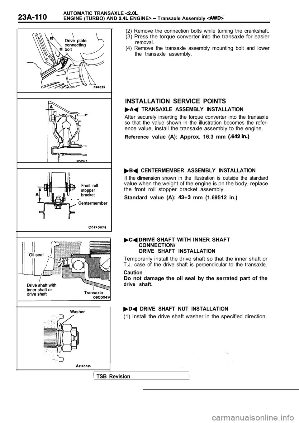
(2) Remove the connection bolts while turning the crankshaft.
(3) Press the torque converter into the transaxle for easier
removal.
(4) Remove the transaxle assembly mounting bolt and lower
the transaxle assembly.
INSTALLATION SERVICE POINTS
TRANSAXLE ASSEMBLY INSTALLATION
After securely inserting the torque converter into the transaxle
so that the value shown in the illustration becomes the refer-
ence value, install the transaxle assembly to the engine.
Reference value (A): Approx. 16.3 mm
CENTERMEMBER ASSEMBLY INSTALLATION
If the shown in the illustration is outside the standard
value when the weight of the engine is on the body, replace
the front roll stopper bracket assembly.
Standard value (A):
mm (1.69512 in.)
SHAFT WITH INNER SHAFT
CONNECTION/ DRIVE SHAFT INSTALLATION
Temporarily install the drive shaft so that the inn er shaft or
T.J. case of the drive shaft is perpendicular to th e transaxle.
Caution
Do not damage the oil seal by the serrated part of the
drive shaft.
DRIVE SHAFT NUT INSTALLATION
(1) Install the drive shaft washer in the specified direction.
TSB RevisionI
Page 1203 of 2103
AUTOMATIC TRANSAXLE
ENGINE (NON-TURBO)>
Transmission
I
Front roll
stopper bracket
ber
T O R Q U E
ASSEMBLY MOUNTING
(1)Use a transmission jack to support
Caution
the
(2) To make installation easier, use chalk to make mating
marks on the torque converter and drive plate.
(3)Remove the connection turning the crankshaft.
(4) the torque converter into the for easier
(5) the transaxle, assembly and lower
the transaxle
ASSEMBLY INSTALLATION
If the dimension shown in the illustration is outsi de the standard
value when the weight of the engine is on the body, replace
the front roll stopper bracket assembly.
Standard value (A)
mm in.)
DRIVE SHAFT CONNECTION’
Temporarily install the drive shaft so that the case of the
drive shaft is perpendicular to the
Caution
Do not damage the oil seal lip by the serrated part of
the drive shaft.
TSB Revision
Page 1418 of 2103
the weights of the pullers against the
of the tools to loosen the pump. on input
while loosening pump. ,
o i l p u m p .
.
oil pump gasket.
,
,,
TSB Revision
Page 1475 of 2103
AUTOMATIC TRANSAXLE OVERHAUL Oil Pump
DISASSEMBLY
R e m o v e p u m p .
(2) Installer Puller Set on bolts holes.
(3) Strike the weights of the pullers against bolt heads
of the tools to loosen the
in” on shaft
while loosening pump.
,
(4) Remove oil pump.
(5) Remove oil pump gasket.