Page 187 of 2103
E N G I N E Engine
A/C COMPRESSOR REMOVAL
the A/C compressor connector and remove the
compressor from the compressor bracket with the
attached.
NOTE
Place the removed A/C compressor in a place where i t will
not be a hindrance when removing and installing the engine
assembly, and tie it with a cord.
Caution
Do not bend the joint between the A/C hose and the A/C
pipe by force.
M O U N T B R A C K E T
REMOVAL
(1) Support the engine with a garage jack.
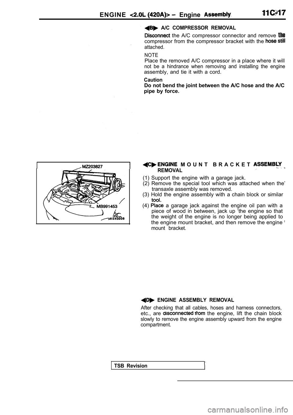
(2) Remove the special tool which was attached when the’
transaxle assembly was removed.
(3) Hold the engine assembly with a chain block or similar
(4) a garage jack against the engine oil pan with a
piece of wood in between, jack up ‘the engine so th at
the weight of the engine is no longer being applied to
the engine mount bracket, and then remove the engin e
mount bracket.
ENGINE ASSEMBLY REMOVAL
After checking that all cables, hoses and harness connectors,. ..etc., are the engine, lift the chain block
slowly to remove the engine assembly upward from th e engine
compartment.
TSB Revision
Page 205 of 2103
ENGINE Timing Belt
REMOVAL SERVICE POINTS
POWER STEERING OIL PUMP
Remove the power steering oil pump from the bracket with
the hose attached.
Place the removed power pump in a place where
it will not be a hindrance when removing and instal ling ‘the
timing belt, and tie it with a cord.
ENGINE MOUNT BRACKET ASSEMBLY REMOVAL
I
sprocket
pulley
Place a garage jack against the engine oil pan with a
of wood in between, jack up the engine so that weight
of the engine is no longer being applied to the eng ine mount
bracket, and then remove the mount bracket.
BELT REMOVAL.
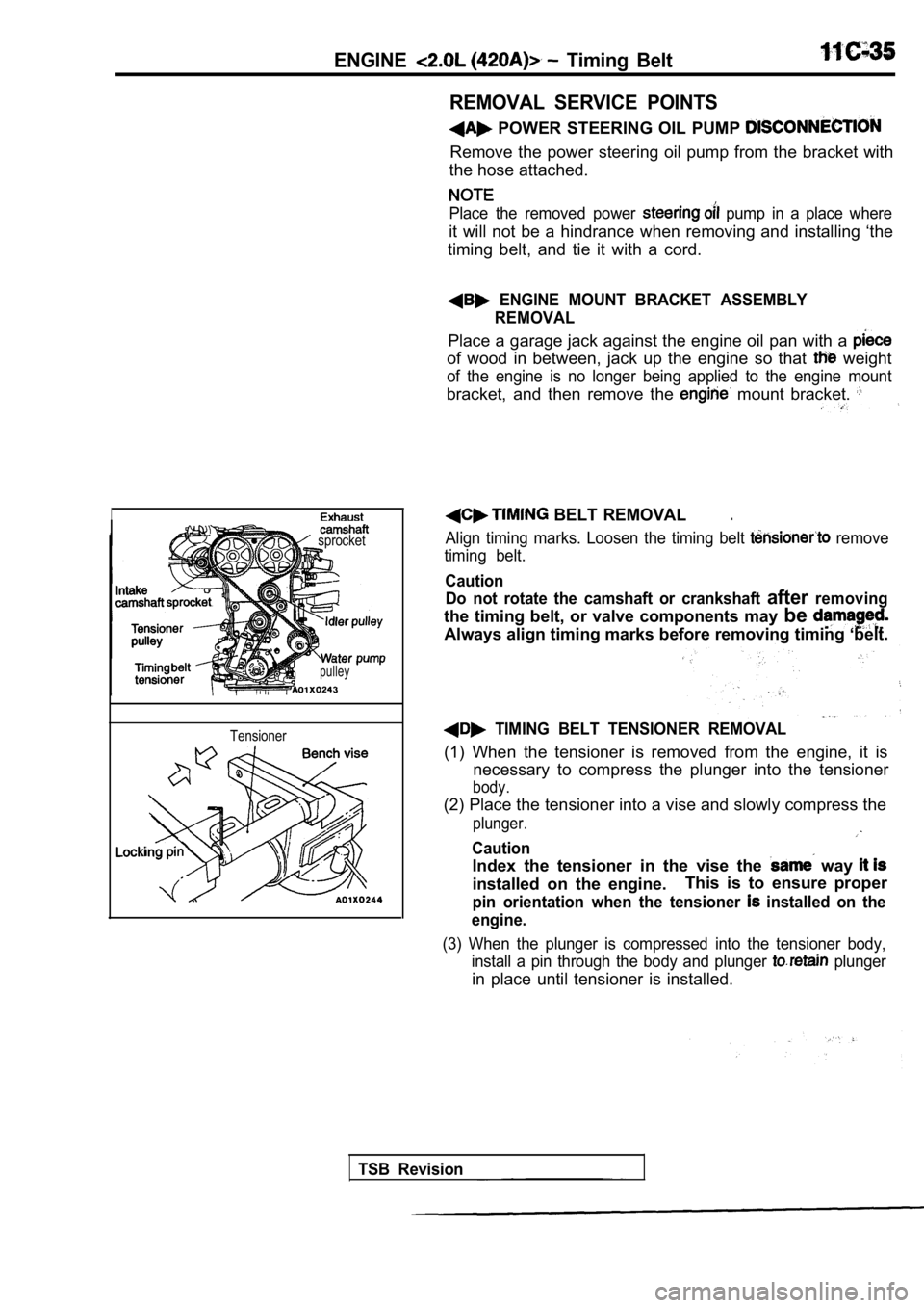
Align timing marks. Loosen the timing belt remove
timing belt.
Caution Do not rotate the camshaft or crankshaft
afterremoving
the timing belt, or valve components may be
Always align timing marks before removing timing ‘b elt.
TIMING BELT TENSIONER REMOVAL
(1) When the tensioner is removed from the engine, it is
necessary to compress the plunger into the tensione r
body.
(2) Place the tensioner into a vise and slowly compress the
plunger.
Caution
Index the tensioner in the vise the way
installed on the engine.This is to ensure proper
pin orientation when the tensioner installed on the
engine.
(3) When the plunger is compressed into the tension er body,
install a pin through the body and plunger
plunger
in place until tensioner is installed.
Tensioner
TSB Revision
Page 267 of 2103
ENGINE
BEARING CLEARANCE
(1) The. total: clearance of the main bearings can only be
determined by removing the weight of the crankshaft .
This is accomplished by having the engine turned upside
down on the engine stand. This will remove all the crank-
weight off the bearing surface.
(2) Place, a piece of Plastigage across the entire width of
the bearing shell in the approximately 6.35 mm
in.) off center and away from the oil holes. In addition,
suspect areas can be checked by placing the Plastig age
in the suspect area.
Torque the
bolts of the bearing being checked
to the proper specifications.
Caution
Do not rotate crankshaft, or the Plastigage may be
smeared.
(3) Remove the and compare the width of the flat-
tened Plastigage with the metric scale provided on the
package.
Standard value: mm in.)
Stretched
boltThreads are straight on line,
Unstretched bolt
MAIN BEARING BOLTS
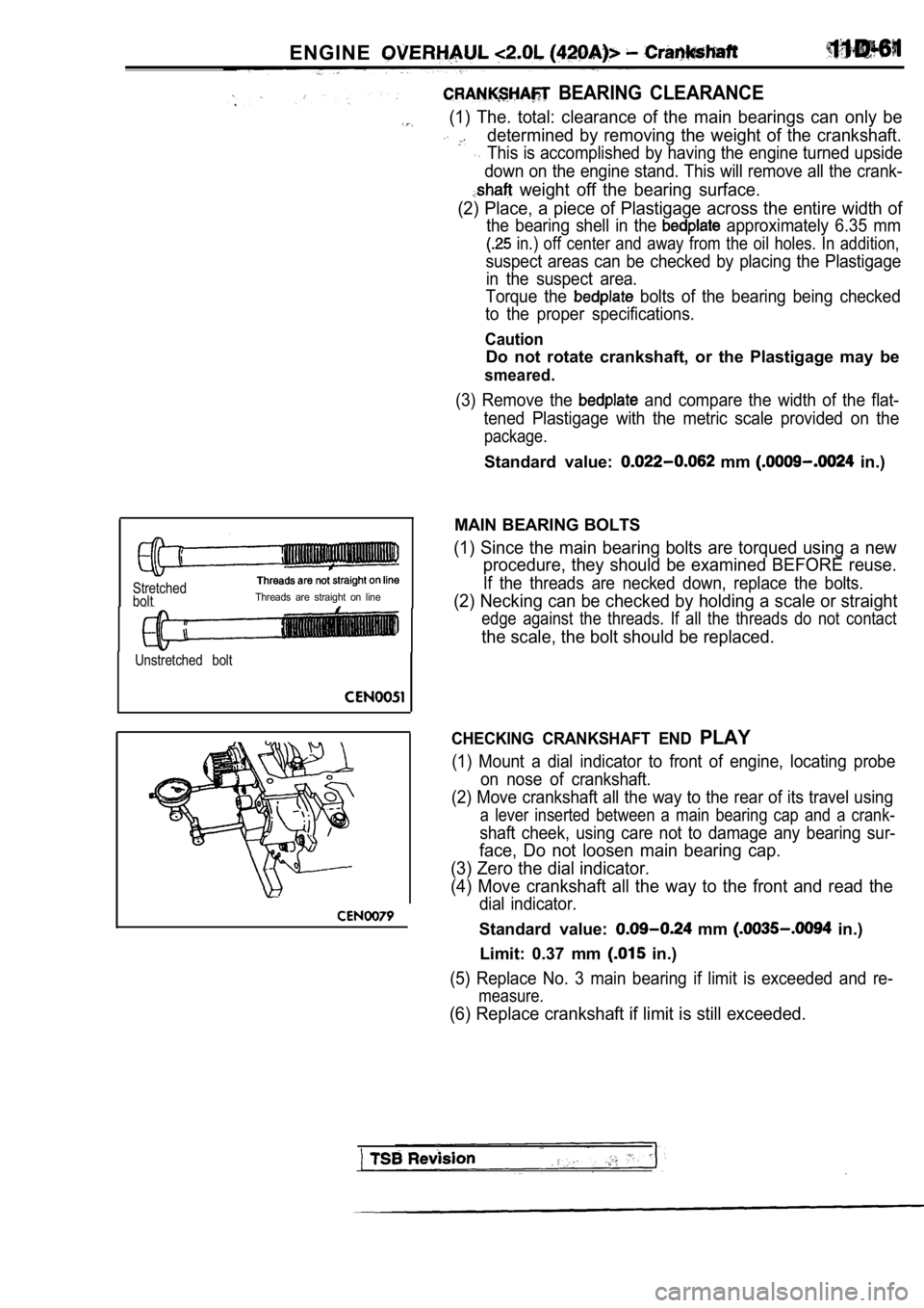
(1) Since the main bearing bolts are torqued using a new
procedure, they should be examined BEFORE reuse.
If the threads are necked down, replace the bolts.
(2) Necking can be checked by holding a scale or st raight
edge against the threads. If all the threads do not contact
the scale, the bolt should be replaced.
CHECKING CRANKSHAFT END PLAY
(1) Mount a dial indicator to front of engine, locating probe
on nose of crankshaft.
(2) Move crankshaft all the way to the rear of its travel using
a lever inserted between a main bearing cap and a c rank-
shaft cheek, using care not to damage any bearing sur-
face, Do not loosen main bearing cap.
(3) Zero the dial indicator.
(4) Move crankshaft all the way to the front and re ad the
dial indicator.
Standard value: mm in.)
Limit: 0.37 mm
in.)
(5) Replace No. 3 main bearing if limit is exceeded and re-
measure.
(6) Replace crankshaft if limit is still exceeded.
Page 286 of 2103
REMOVAL SERVICE POINTS
POWER STEERING PUMP REMOVAL
power steering pump from the bracket with the
hose attached.
NOTE
Place the removed power steering pump in a place wh ere
will not be a hindrance when removing and installing the
engine assembly, and tie it with a cord.
A/C COMPRESSOR REMOVAL
Disconnect the compressor connector and remove the
compressor from the compressor bracket with the hos e still
a t t a c h e d .
NOTE:
Place the removed A/C compressor in a place where i t will
not be
hindrance when removing and installing the engine
assembly, and tie it with a cord.
Do not bend the joint between hose and the A/C
pipe
force.
E N G I N E A S S E M B L Y
REMOVAL,
(1) Support the a garage
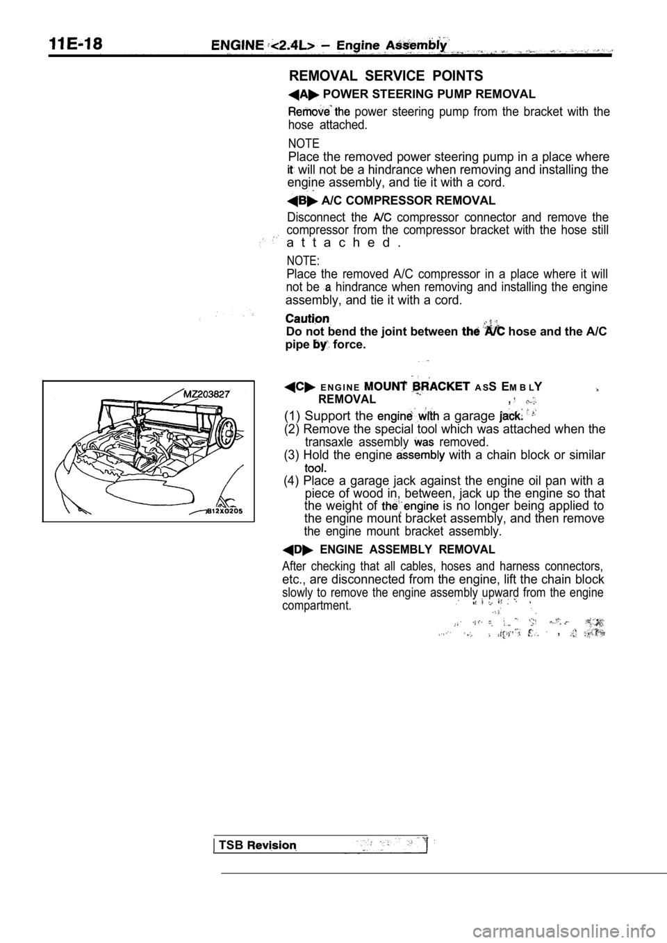
(2) Remove the special tool which was attached when the
transaxle assembly removed.
(3) Hold the engine with a chain block or similar
(4) Place a garage jack against the engine oil pan with a
piece of wood in, between, jack up the engine so th at
the weight of
is no longer being applied to
the engine mount bracket assembly, and then remove
the engine mount bracket assembly.
ENGINE ASSEMBLY REMOVAL
After checking that all cables, hoses and harness c onnectors,
etc., are disconnected from the engine, lift the chain block
slowly to remove the engine assembly upward from th e engine
compartment.
,
TSB
Page 873 of 2103
MANUAL TRANSAXLE
ENGINE (TURBO) AND ENGINE> Transaxle Assembly
TransaxlemountTransaxle side
stopper
Front roll
member
CLUTCH.
Remove the clutch release cylinder without disconne cting
the oil line, and suspend
a nearby “a
etc.
INSTALLATION SERVICE POINT
TRANSAXLE MOUNTING
Align the notches on the stopper with the transaxle mount
bracket with the arrow mark facing toward the shown direction.
Then install the stopper.
CENTER MEMBER
If the dimension shown in the outside the standard
value when the weight of the engine is on the body;, replace
the front roll stopper bracket assembly. ,
Standard value (A): 43
3 mm (1.69 in.)
DRIVE SHAFT
Temporarily install the drive shaft so that the T.J . case of
the drive shaft is perpendicular to the transaxle.
Caution
Do not damage the oil seal lip by the serrated part of
the drive shaft.
TSB Revision. .
Page 876 of 2103
MANUAL TRANSAXLE
ENGINE AND ENGINE> Transaxle Assembly
I -
Cord
I’ --
Nut
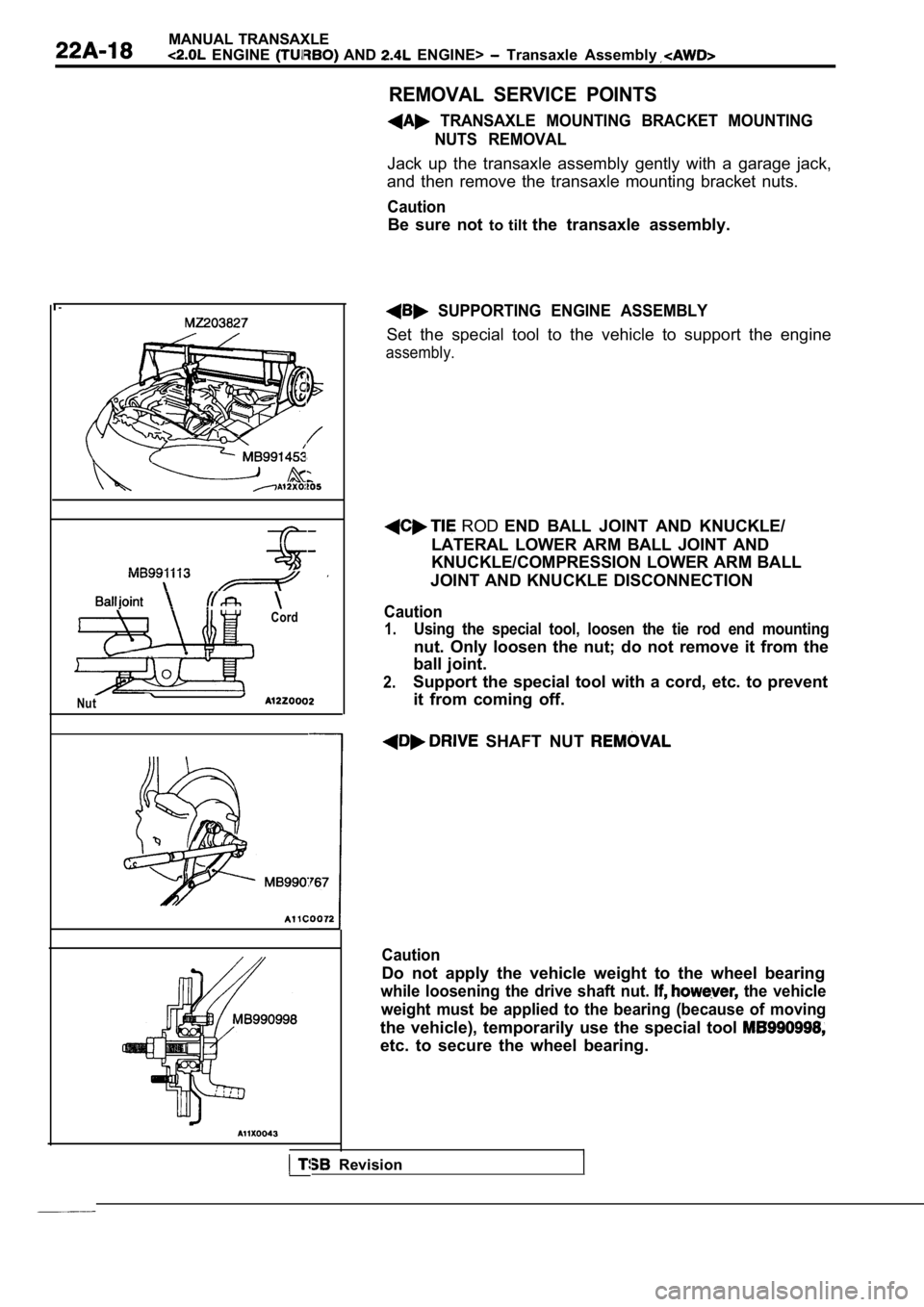
REMOVAL SERVICE POINTS
TRANSAXLE MOUNTING BRACKET MOUNTINGNUTS REMOVAL
Jack up the transaxle assembly gently with a garage jack,
and then remove the transaxle mounting bracket nuts .
Caution
Be sure not to tilt the transaxle assembly.
SUPPORTING ENGINE ASSEMBLY
Set the special tool to the vehicle to support the engine
assembly.
ROD END BALL JOINT AND KNUCKLE/
LATERAL LOWER ARM BALL JOINT AND
KNUCKLE/COMPRESSION LOWER ARM BALL
JOINT AND KNUCKLE DISCONNECTION
Caution
1.Using the special tool, loosen the tie rod end moun ting
nut. Only loosen the nut; do not remove it from the
ball joint.
2.Support the special tool with a cord, etc. to preve nt
it from coming off.
SHAFT NUT
Caution
Do not apply the vehicle weight to the wheel bearin g
while loosening the drive shaft nut. the vehicle
weight must be applied to the bearing (because of m oving
the vehicle), temporarily use the special tool
etc. to secure the wheel bearing.
I Revision
Page 878 of 2103
MANUAL TRANSAXLE
ENGINE (TURBO) AND ENGINE> Transaxle Assembly
TransaxlemountTransaxle side
s t o p p e r ,ArrowTransaxlemount
Frontstopperbracket
member
Revision
Washer
196-255 Nm
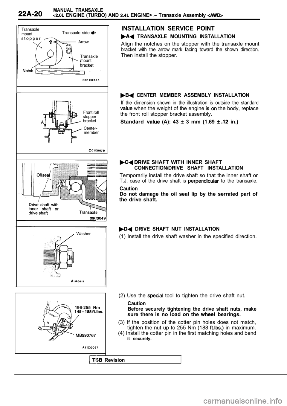
INSTALLATION SERVICE POINT
TRANSAXLE MOUNTING INSTALLATION
Align the notches on the stopper with the transaxle mount
bracket with the arrow mark facing toward the shown direction.
Then install the stopper.
CENTER MEMBER ASSEMBLY INSTALLATION
If the dimension shown in the illustration is outside the standard
when the weight of the engine the body, replace
the front roll stopper bracket assembly.
Standard
(A): 43 3 mm (1.69 in.)
SHAFT WITH INNER SHAFT
CONNECTION/DRIVE SHAFT INSTALLATION
Temporarily install the drive shaft so that the inn er shaft or
T.J. case of the drive shaft is to the transaxle.
Caution
Do not damage the oil seal lip by the serrated part of
the drive shaft.
DRIVE SHAFT NUT INSTALLATION
(1) Install the drive shaft washer in the specified direction.
(2) Use the
tool to tighten the drive shaft nut.
Caution Before securely tightening the drive shaft nuts, ma ke
sure there is no load on the bearings.
(3) If the position of the cotter pin holes does no t match,
tighten the nut up to 255 Nm (188
in maximum.
(4) Install the cotter pin in the first matching ho les and bend
it securely.
Page 890 of 2103
MANUAL. TRANSAXLE
ENGINE (NON-TURBO)> Transaxle Control
Frontstopper
bracket
member
ASSEMBLY INSTALLATION
If the dimension shown in the illustration is outside the standard
value when the’ weight of the engine is on the body , replace
the front roll stopper bracket assembly.
Standard value (A): 43
3 mm (1.69 in.)
SHAFT CONNECTION
Temporarily install the drive shaft so that the T.J . case of
the drive shaft is perpendicular to the transaxle.
Caution
Do not damage the oil seal lip by the serrated part of
the drive shaft.
Transaxle case
Revision