Page 509 of 2103
On-vehicle Inspection of
ENGINE
TEMPERATURE SENSOR
CHECK
1. Disconnect the engine coolant temperature sensor
connector.
2. Measure the resistance between the sensor terminals.
INSTALLATION
1. Apply sealant to threaded
Specified sealant: Loctite 24200 or equivalent
2.
engine coolant sensor tighten
it to specified torque.
Sensor tightening torque: 7 (5
3. Fasten harness connectors securely.
THROTTLE POSITION SENSOR CHECK
1. the throttle position sensor connector.
2. Measure the resistance between the throttle posi tion
sensor side connector terminal 1 and terminal 3.
Standard value:
3. Measure the resistance between the throttle
sensor side, connector terminal 2 terminal 3.
Throttle valve slowly open until
fully open from the idle positionChanges smoothly in
t o t h e
angle of the
4. If the resistance is outside the standard value, ‘if it
doesn’t change smoothly, replace the throttle posit ion
sensor.
TSB Revision
Page 510 of 2103

On-vehicle of
ENGINE ( N O N - T U R B O ) >
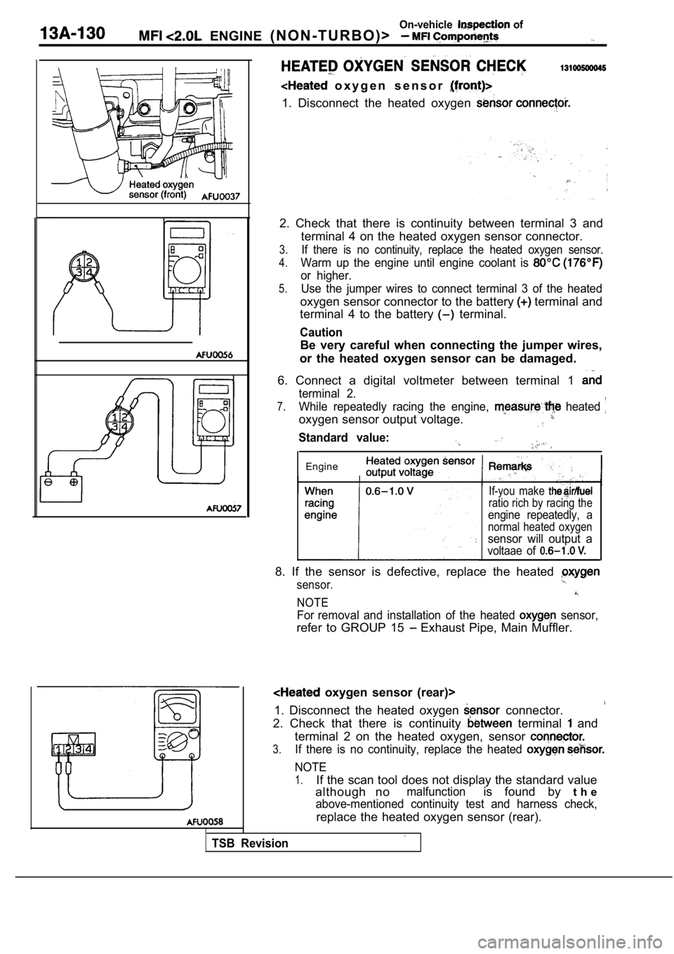
o x y g e n s e n s o r
1. Disconnect the heated oxygen
2. Check that there is continuity between terminal 3 and
terminal 4 on the heated oxygen sensor connector.
3.If there is no continuity, replace the heated oxyge n sensor.
4.Warm up the engine until engine coolant is
or higher.
5.Use the jumper wires to connect terminal 3 of the h eated
oxygen sensor connector to the battery terminal and
terminal 4 to the battery
terminal.
Caution
Be very careful when connecting the jumper wires,
or the heated oxygen sensor can be damaged.
6. Connect a digital voltmeter between terminal 1
terminal 2.
7.While repeatedly racing the engine, heated
oxygen sensor output voltage.
Standard value:
Engine
TSB Revision
If-you make
ratio rich by racing the
engine repeatedly, a
normal heated oxygen
sensor will output a
voltaae of
8. If the sensor is defective, replace the heated
sensor.
NOTE
For removal and installation of the heated sensor,
refer to GROUP 15 Exhaust Pipe, Main Muffler.
oxygen sensor (rear)>
1. Disconnect the heated oxygen
connector.
2. Check that there is continuity terminal and
terminal 2 on the heated oxygen, sensor
3.If there is no continuity, replace the heated
NOTE
1.If the scan tool does not display the standard valu e
although no
malfunctionis found by t h e
above-mentioned continuity test and harness check,
replace the heated oxygen sensor (rear).
Page 512 of 2103

32On-vehicle, Inspection of
(NON-TURBO)>
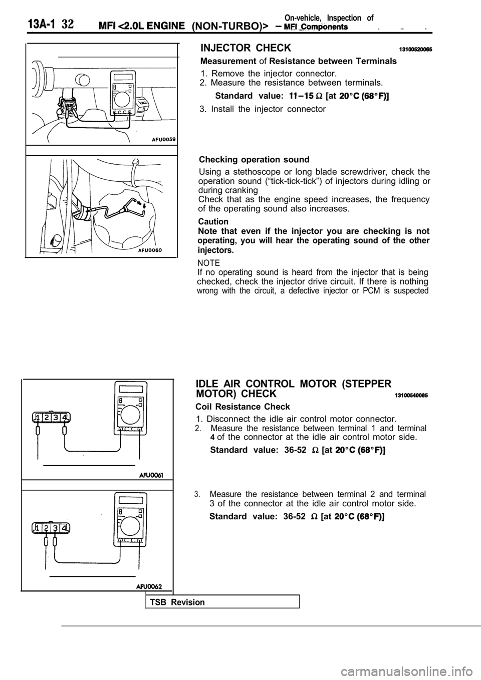
INJECTOR CHECK
MeasurementofResistance between Terminals
1. Remove the injector connector.
2. Measure the resistance between terminals.
Standard value:
[at
3. Install the injector connector
Checking operation sound
Using a stethoscope or long blade screwdriver, chec k the
operation sound (“tick-tick-tick”) of injectors dur ing idling or
during cranking
Check that as the engine speed increases, the frequ ency
of the operating sound also increases.
Caution
Note that even if the injector you are checking is not
operating, you will hear the operating sound of the other
injectors.
NOTE
If no operating sound is heard from the injector th at is being
checked, check the injector drive circuit. If there is nothing
wrong with the circuit, a defective injector or PCM is suspected
IDLE AIR CONTROL MOTOR (STEPPER
MOTOR) CHECK
Coil Resistance Check
1. Disconnect the idle air control motor connector.
2.Measure the resistance between terminal 1 and termi nal
4of the connector at the idle air control motor side .
Standard value: 36-52
[at
3.Measure the resistance between terminal 2 and termi nal
3 of the connector at the idle air control motor side.
Standard value: 36-52
[at
TSB Revision
Page 513 of 2103
On-vehicle Inspection of
ENGINE (NON-TURBO)>
EVAPORATIVE EMISSION PURGE
CHECK
1 7 ’
ELECTRIC EGR
Refer to GROUP 17 Emission Control
TSB Revision
Page 515 of 2103
ENGINE (NON-TURBO)>
REMOVAL SERVICE POINT,
F U E L
Remove the fuel rail the attached’
,
Do not drop the injector.
INSTALLATION SERVICE POINTS
INJECTORS INSTALLATION
(1) Apply a small amount of clean engine oil to the O-ring.
Caution
Donot let the engine oil get into the fuel rail.
(2) While turning the injector to the left and righ t, install it
to the fuel rail.
(3) Check to be sure that the injector turns smooth ly.
If it does not turn smoothly, the O-ring may be tra pped,
remove the injector and then reinsert it into the f uel
and check again.
HIGH-PRESSURE FUEL HOSE CONNECTION
When connecting the high-pressure fuel hose to the fuel rail,
apply a small amount of engine oil to the hose union, and
then insert, being careful not to damage the O-ring .
Caution
Do not let the engine get .
TSB Revision
Page 517 of 2103
ENGINE (NON-TURBO)> Throttle Body
DISASSEMBLY AND REASSEMBLY
2.2
2I
. .
1. .
steps
1. motor assembly2. Throttle body
DISASSEMBLY SERVICE POINT
MOTOR REMOVAL
Do not disassemble the motor.
2.Do not immerse solvent to clean the sensor and moto r.
Clean them with shop towel.
THROTTLE BODY REMOVAL
1. Do not remove the throttle valve.
2. Check if the vacuum port or passage is clogged. Use
compressed air to clean the vacuum passage.
TSB Revision
Page 519 of 2103

ENGINE (TURBO)
ENGINE>
DIAGNOSTIC TEST MODEl When an abnormality is detected in one
of the sensors or actuators related to emis-
sion control, the CHECK
FUNCTION INDICATOR LAMP illuminates
as a warning to the driver.
l When an abnormality is detected in one
of the’ sensors or actuators, a
OTHER CONTROL FUNCTIONS
1. Fuel Pump Control
Turns the fuel pump relay ON current
is supplied to the fuel pump while the engine
is cranking or running.
2. A/C Compressor Clutch Relay Control Turns the A/C compressor clutch ON and
OFF.
3. Fan Relay Control
The radiator fan and condenser fan speeds
are controlled in response to the engine
coolant temperature and vehicle speed.
4. Fuel
Control
Supplies current to fuel pressure solenoid
coil to raise the fuel pressure so that the
fuel does not vaporize when the engine
is started while it is warm.
trouble code ‘the,,
normality is output.
lThe RAM data inside the that
to the sensors and actuators can be read’
by
scan’ tool.
addition, the actuators can be controlled
under certain
5. Charge Control
Controls the intake charge pressure by con-
trolling the duty of the turbocharger
gate solenoid!
6. Intake Pressure Gauge’ Control Indicates the intake charge pressure on
the
7. Generator Output Current Control
Prevents generator output current from in-
creasing idle speed from
dropping at times such as when the head-
lights are turned on.
8.Evaporative Emission Purge Solenoid Con-
trol Engine (TURBO)>
Refer to
17.
Evaporative Emission Purge Solenoid Con-
trol GROUP 17.
9. EGR Solenoid’ Control
Refer to GROUP
,,
,
TSB Revision
Page 527 of 2103

E N G I N E ( T U R B O )
AND
ENGINE>
DIAGNOSTIC TEST MODE
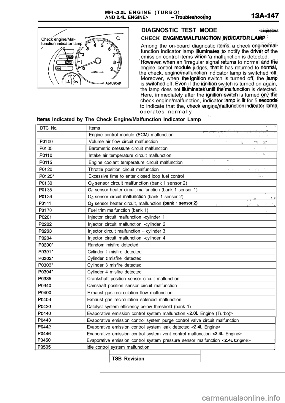
CHECK
Among the on-board diagnostic a check
function indicator lamp notify the the
emission control items
‘a malfunction is detected.
an ‘irregular signal to normal
engine control judges, has returned to
the check. indicator lamp is switched
Moreover, when switch is turned off, the
is off. if the switch is turned on again,
the lamp does not is detected.
Here, immediately after the is turned
check engine/malfunction, indicator is for 5
to indicate that the,
o p e r a t e s n o r m a l l y .
Indicated by The Check Engine/Malfunction Indicato r Lamp
00
05
20
30
35
36
41
70
Items
Engine control module
malfunction
Volume air flow circuit malfunction
Barometric
circuit malfunction
Intake air temperature circuit malfunction
Engine coolant temperature circuit malfunction
Throttle position circuit malfunction
Excessive time to enter closed loop fuel control
sensor circuit malfunction (bank 1 sensor 2)
sensor heater circuit malfunction (bank 1 sensor 1 )
sensor circuit (bank 1 sensor 2).
sensor heater circuit, malfunction 1
Fuel trim malfunction (bank 1)
Injector circuit malfunction -cylinder 1
Injector circuit malfunction -cylinder 2
Injector circuit malfunction
cylinder 3
Injector circuit malfunction -cylinder 4
Random misfire detected
Cylinder
misfire detected
Cylinder
2misfire detected
Cylinder 3 misfire detected Cylinder 4 misfire detected
Crankshaft position sensor circuit malfunction
Camshaft position sensor circuit malfunction
Exhaust gas recirculation flow malfunction
Exhaust gas recirculation solenoid malfunction
Catalyst system efficiency below threshold (bank 1) Evaporative emission control system malfunction
Engine (Turbo)>
Evaporative emission control system purge control v alve circuit malfunction
Evaporative emission control system leak detected
Engine>
Evaporative emission control system vent control ma lfunction
Engine>
Evaporative emission control system pressure sensor malfunction
control system malfunction
DTC No.
TSB Revision