Page 1289 of 2103
A U T O M A T I C T R A N S A X L E
OVERHAUL
HYDRAULIC CONTROL SYSTEM
, ,
1.Torque converter
2. Front clutch
3. Rear clutch
4.Low-reverse brake5.End clutch6. servo7.Transaxle control module
8. Torque converter clutch control valve
9. Torque converter clutch solenoid
10. Rear clutch exhaust valve11. shift valve12.Reducing valve
13. Shift control solenoid valve “A” 14.
shift valve
15.End clutch valve
16. Torque converter
17. Shift control solenoid valve 18.Shift control valve19.N-D control valve20.Regulator valve21.Manual valve22. Pressure control valve
23. Oil pump
24. Oil filter
25.Oil pan
2 6 . Line relief valve
27. N-R control valve
Pressure control solenoid,
TSB Revision
Page 1291 of 2103
AUTOMATIC TRANSAXLE
OVERHAUL
Transfer driven gear preload (Center differential preload) mm (in.) 0.135
Low-reverse brake end play mm
Input shaft end play mm (in.)
case preload mm (in.)
Front differential case end play mm (in.)
Differential gear and pinion backlash mm (in.)
Oil pump side clearance mm (in.)
Output flange bearing end play mm (in.)Front clutch end play mm (in.)
Rear clutch end play mm (in.)
End clutch end play mm (in.)
Transfer drive gear end play mm (in.)
Front output shaft preload
mm (in.)
‘Center differential side gear end play
mm (in.)
Bevel gear set backlash
mm (in.)
Driven bevel gear turning drive torque
Nm
Drive bevel gear shaft turning drive torque Nm
(07.0035)
VALVE BODY SPRING IDENTIFICATION CHART
TSB Revision
Page 1295 of 2103

A U T O M A T I C T R A N S A X L E
OVERHAUL
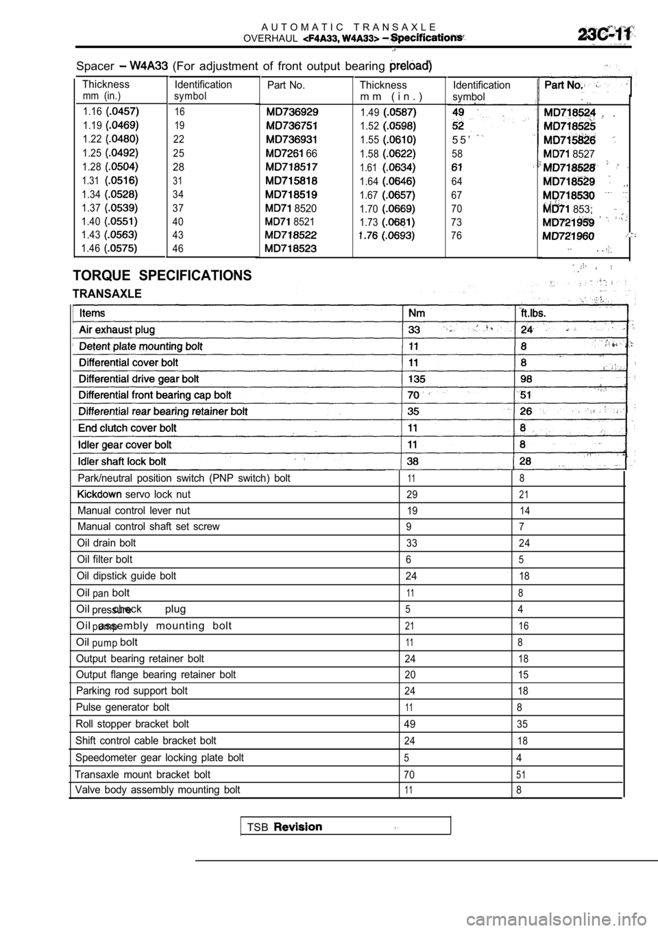
Spacer (For adjustment of front output bearing
Thickness Identification
mm (in.) symbol
1.16
16
1.1919
1.2222
1.25
25
1.28
28
1.3131
1.3434
1.37
37
1.40
40
1.43
43
1.46
46
TORQUE SPECIFICATIONS
TRANSAXLE
Part No.
66
8520
8521
Thickness
m m ( i n . )
1.49
1.52
1.55
1.58
1.61
1.64
1.67
1.70
1.73
Identification
symbol
5 5 ’
58
64
67
70
73
76
.
8527
853;
. .
.
Park/neutral position switch (PNP switch) bolt118
servo lock nut2921
Manual control lever nut1914
Manual control shaft set screw9 7
Oil drain bolt33 24
Oil filter bolt65
Oil dipstick guide bolt 2418
Oil boltpan118
Oil check plugpressure54
Oil assembly mounting boltpump2116
Oil boltpump118
Output bearing retainer bolt2418
Output flange bearing retainer bolt20 15
Parking rod support bolt24 18
Pulse generator bolt118
Roll stopper bracket bolt4935
Shift control cable bracket bolt2418
Speedometer gear locking plate bolt54
Transaxle mount bracket bolt
7051
Valve body assembly mounting bolt118
TSB
Page 1303 of 2103
AUTOMATIC TRANSAXLE
OVERHAUL
50.Bearing. retainer51. Thrust bearing 52. End clutch hub53.Thrust washer
54. End clutch assembly
55.O-ring56. End clutch cover57.Pulse generator58.Lock bolt59.Idler shaft60.Idler gear61.Spacer
64. bearing- 65. Outer 66. Diff
67.
I-, front a s s e m b l y ,
68. ,
69. cover
7 0 . - -
72..
(1) Clean away any sand, the’
transaxle.
(2) Place the transaxle assembly
oil pan down.
(3) Remove the torque converter;
(4)Use the special tool to mount
axle case and measure ‘the.
. .
. .
.
(5) Remove the pulse
. . .
. . .a-.
(6) Remove the manual control lever, ‘then
neutral position switch (PNP
,
. .
(7) Remove the oil pan, magnets and
.
,
,
, .
.
TSB Revision
Page 1313 of 2103

A U T O M A T I C T R A N S A X L E
OV E R HAUL -Transaxle
I
68
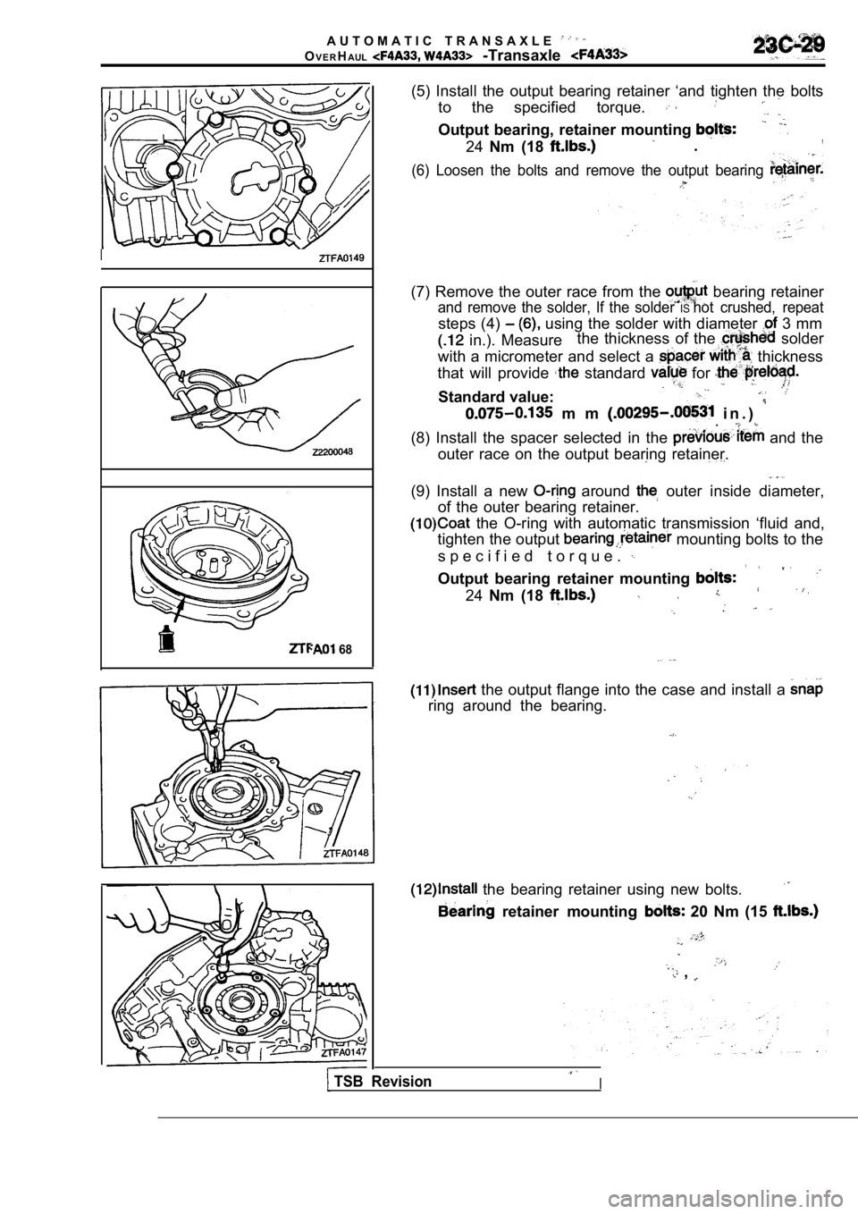
(5) Install the output bearing retainer ‘and tighte n the bolts
to the specified torque.
Output bearing, retainer mounting
24 Nm (18 .,
(6) Loosen the bolts and remove the output bearing
(7) Remove the outer race from the bearing retainer
and remove the solder, If the solder IShot crushed, repeat
steps (4) using the solder with diameter 3 mm
in.). Measure the thickness of the solder
with a micrometer and select a
thickness
that will provide
standard for
Standard value:
m m i n . ) .
(8) Install the spacer selected in the and the
outer race on the output bearing retainer.
(9) Install a new around outer inside diameter,
of the outer bearing retainer.
the O-ring with automatic transmission ‘fluid and,
tighten the output
mounting bolts to the
s p e c i f i e d t o r q u e .
Output bearing retainer mounting
24 Nm (18
the output flange into the case and install a
ring around the bearing.
the bearing retainer using new bolts.
retainer mounting 20 Nm (15
,
TSB RevisionI
Page 1321 of 2103
AUTOMATICOVERHAUL
end play of the input
value, replace race thrust washer
to the standard
Standard value:
the idler shaft lock bolt
lock to the specified torque.
of the lock plate prevent
Idler shaft lock bolt:
,
. .
.. .
the idler cover new
Idler gear cover’ (8
spacer, idler gear arid
the idler shaft.
Caution
Assemble so that the on
i d l e r g e a r f a c e s .
I-
. ,
,
.
. .
the clutch shaft ‘from
spline.
--. . .
I.
,
TSB Revision
Page 1323 of 2103
A U T O M A T I C T R A N S A X L E
OVERHAUL
the end clutch cover tighten the
specified torque.’
End cover mounting
assembly.
with a length mm
in.) and diameter of 1.6 mm in.) on the
rear bearing retainer at the position shown the diagram
and install the outer race.
the differential rear
the to the specified torque:
the bolts, remove the differential
remove the if solder is
repeat steps (51) using the solder with the diameter
of 3 mm.
Differential rear bearing retainer bolts:
35Nm (26
,
the of the
and adjust by selecting a
that will provide the value and
preload..
S t a n d a r d v a l u e :
,,
TSB Revision
Page 1324 of 2103
AUTOMATIC TRANSAXLE
OVERHAUL
-Transaxle
a new O-ring on the rear bearing retainer,
coat the O-ring with automatic transmission fluid,; then
install in the transaxle case and tighten the mount ing
bolts to the specified torque.
Differential rear bearing
mounting
35 Nm (26
the front bearing cap and tighten the bolts to the
specified torque..
Differential front bearing cap mounting bolts: 70 Nm (51
the differential cover and a new gasket.
Differential cover mounting bolts: 11 Nm (8
the detent plate.
Detent plate mounting bolt: 11 Nm (8
,,
a new O-ring on the manual control shaft assembly,
coat the O-ring with automatic
and then
insert into the transaxle case.
the groove in the manual control shaft and the set
screw hole; then install the set screw.
Manual
shaft set screw: 9 (7
the parking roller support.
Parking roller support bolts: 24 Nm (18
TSB RevisionI