Page 1610 of 2103
FRONT SUSPENSION Shock Absorber
Damper foinstallation
of the body
REASSEMBLY. SERVICE
COIL SPRING INSTALLATION
(1) Use the special tools to
the coil spring and
install it to the shock absorber.
Caution
Do not use an impact wrench to tighten the bolt of
the special tool.
(2) Align the edge of the coil spring to the steppe d part of
the shock
spring seat.
UPPER BRACKET ASSEMBLY
so that the position as’
in the illustration with respect the fork installation
bolt.
. SELF-LOCKING NUT . .
( 1 )
(2). the special tools and
tighten the
to- the ,
Caution
Do not use an impact wrench.
TSB Revision
Page 1611 of 2103
Compression Lower and
FRONT SUSPENSION
Lower Arm
COMPRESSION LOWER ARM AND LATERAL ARM
ASSEMBLIES
REMOVAL AND INSTALLATION
Post-installation OperationlFront Alignment Adjustment(Refer to ,
98-118
\ 6 9 - 7 8
Compression lower arm assemblyremoval steps
1. Compression lower arm bail joint
and knuckle connection
2. Compression lower arm mounting
bolts3. Compression lower arm assembly
Lateral lower arm assemblyremoval steps
4.
Stay5. absorber lower mounting
6. Lateral lower arm ball joint and
knuckle connection7. Lateral lower arm mounting bolt
8. Lateral lower arm assembly
CautionIndicates parts which should be tightened,
and then fully tightened with the on the ground
in the unladen condltlon.
TSB Revision
Page 1612 of 2103

FRONT SUSPENSION
REMOVAL SERVICE POINT
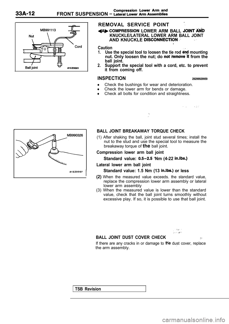
LOWER ARM BALL
KNUCKLE/LATERAL LOWER ARM BALL JOINT
AND KNUCKLE .
Caution
1.Use the special tool to loosen the tie rod mounting
nut. Only loosen the nut; do from the
ball joint.
2.Support the special tool with a cord, etc. to prevent
it from coming off.
INSPECTION29299929959
lCheck the bushings for wear and deterioration.
lCheck the lower arm for bends or damage.
lCheck all bolts for condition and straightness.
BALL JOINT BREAKAWAY TORQUE CHECK
(1) After shaking the ball, joint stud several time s; install the
nut to the stud and use the special tool to measure the
breakaway torque of theball joint.
Compression lower arm ball joint
Standard value: ‘Nm (4-22
Lateral lower arm ball joint
Standard value: 1.5 Nm (13 or less
(2)
When the measured value exceeds. the standard value ,
replace the compression lower arm assembly or lateral
lower arm assembly
(3) When the measured value is lower than the stand ard
value, check that the ball joint turns smoothly wit hout
excessive play. If so, it is possible to use that b all joint.
BALL JOINT DUST COVER CHECK
If there are any cracks in or damage to dust cover, replace
the arm assembly.
TSB Revision
Page 1613 of 2103
Compression Arm and
FRONT SUSPENSION Lateral Lower Arm Assemblies,
LOWER ARM BALL JOINT
REPLACEMENT
Replace the dust cover by the following procedure only if
the dust cover has become damaged by accident durin g
servicing.
(1) Remove the dust cover.
(2) Apply multipurpose grease to the lip and inside of the
dust cover.
(3)
Using the special tool, drive in the dust cover to the position
shown in the illustration.
TSB Revision
Page 1615 of 2103

FRONT SUSPENSION , ,
Al
Clip ring ends onopposite side also possible)
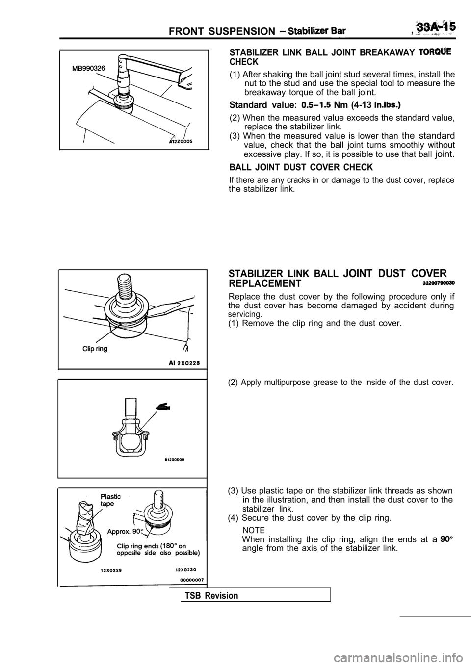
STABILIZER LINK BALL JOINT BREAKAWAY
CHECK
(1) After shaking the ball joint stud several times, install the
nut to the stud and use the special tool to measure the
breakaway torque of the ball joint.
Standard value: Nm (4-13
(2) When the measured value exceeds the standard va lue,
replace the stabilizer link.
(3) When the measured value is lower than the standard
value, check that the ball joint turns smoothly wit hout
excessive play. If so, it is possible to use that b all joint.
BALL JOINT DUST COVER CHECK
If there are any cracks in or damage to the dust co ver, replace
the stabilizer link.
STABILIZER LINK BALL JOINT DUST COVER
REPLACEMENT
Replace the dust cover by the following procedure o nly if
the dust cover has become damaged by accident durin g
servicing.
(1) Remove the clip ring and the dust cover.
(2) Apply multipurpose grease to the inside of the dust cover.
(3) Use plastic tape on the stabilizer link threads as shown
in the illustration, and then install the dust cove r to the
stabilizer link.
(4) Secure the dust cover by the clip ring.
NOTE
When installing the clip ring, align the ends at a
angle from the axis of the stabilizer link.
TSB Revision
Page 1617 of 2103
REAR
SUSPENSION-
CONTENTS
GENERAL INFORMATION2SHOCK ABSORBER ASSEMBLY. . . . . . . . . . .. . . . . . . . . . . . . . . . ..
LOWER ARM AND TOE CONTROL ARMSPECIAL TOOLS. . . . . . . . . . . . . . . . . . . . . . . . . .4
ASSEMBLIES. . . . . . . . . . . . . . . . . . . . . . . . . . . . .12
STABILIZER BAR. . . . . . . . . . . . . . . . . . . . .
REAR SUSPENSION ASSEMBLY. . . . . . . . . .7.
TRAILING ARM . . . . . . . . . . . . . . . . .11
ON-VEHICLE SERVICE. . . . . . . . . . . . . . . . . . . .6
Rear Wheel Alignment Check. . . . . . . . . . . . . . . . . . . . . .6
and Adjustment
. . . . . . . . . . . . . . . . . . . . . . . . . . . . .6UPPER ARM ASSEMBLY. . . . . . . . . . . . . . . . . . . .9
SERVICE SPECIFICATIONS . . . . . . . . . . . . . . . .
4
Page 1618 of 2103

REAR SUSPENSION General Information
GENERAL INFORMATION
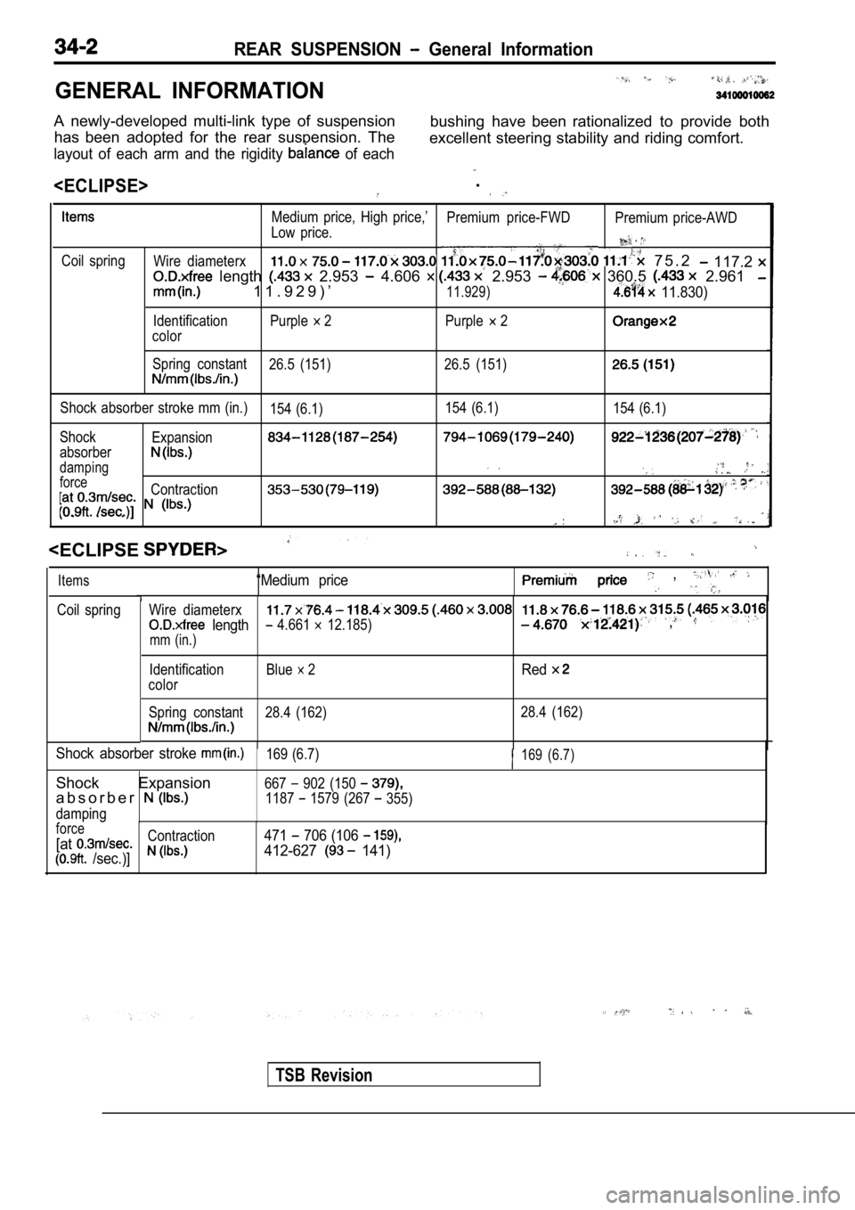
A newly-developed multi-link type of suspensionhas been adopted for the rear suspension. The bushing have been rationalized to provide both
excellent steering stability and riding comfort.
layout of each arm and the rigidity of each
.
Coil spring Medium price, High price,’
Premium price-FWDPremium price-AWD
Low price.Wire diameterx 7 5 . 2 117.2
length 2.953 4.606 2.953 360.5 2.961
1 1 . 9 2 9 ) ’11.929) 11.830)
Identification Purple 2 Purple 2
color
Spring constant 26.5 (151) 26.5 (151)
Shock absorber stroke mm (in.)
154 (6.1)154 (6.1)
154 (6.1)
Shock Expansion
absorber
damping
forceContraction
. . .
“Medium price ,
Wire diameterx
length 4.661 12.185) ,
mm (in.)
Items
Coil spring
TSB Revision
Identification
color Blue 2Red
Spring constant 28.4 (162)
28.4 (162)
Shock absorber stroke 169 (6.7)169 (6.7)
Shock Expansion667 902 (150
a b s o r b e r1187 1579 (267 355)
damping
force
[atContraction471 706 (106
/sec.)]412-627 141)
Page 1619 of 2103
REAR SUSPENSION General Information
Shock absorber
U p p e r a r m
control
with aero
arm
Trailing arm
Differential support arm
00003694
TSB Revision