1990 MITSUBISHI SPYDER reset
[x] Cancel search: resetPage 472 of 2103
![MITSUBISHI SPYDER 1990 Service Repair Manual E N G I N E
INSPECTION PROCEDURE 12 , .
. .
When the engine is hot, it stalls at idle. (Die out )
[Comment]l Malfunction of the ignition In cases such as the above, the caus MITSUBISHI SPYDER 1990 Service Repair Manual E N G I N E
INSPECTION PROCEDURE 12 , .
. .
When the engine is hot, it stalls at idle. (Die out )
[Comment]l Malfunction of the ignition In cases such as the above, the caus](/manual-img/19/57345/w960_57345-471.png)
E N G I N E
INSPECTION PROCEDURE 12 , .
. .
When the engine is hot, it stalls at idle. (Die out )
[Comment]l Malfunction of the ignition In cases such as the above, the cause is probably t hat ignition system, mixture, idle l
air control motor or compression pressure is defect ive.Malfunction control M a l f u n c t i o n o f t h e s y s t e m In addition, if the engine stalls, the cause
mayalso be a defective connector contact.l into intake system
l Improper connector contact
W ere the battery terminals disconnected recently
NO
YES After warming-up, let the engine run at idling for 10 minutes.
SCAN TOOL DTC
Are diagnostic trouble codes output?
NO
SCAN TOOL Actuator test
07 motor. (Refer to
OK YES
N G
Refer to INSPECTION CHART FOR DIAGNOSTICTROUBLE CODES.
Checktheidleaircontrolmotorcircuit. INSPECTIONPROCEDURE FOR DIAGNOSTIC TROUBLE CODE
SCAN TOOL Special function
“Reset
Check trouble symptoms.
NG
Check the injector for operation sound.
(Refer to Check the injector control circuit. Carry out proc edures 20, in “INSPECTION PROCEDURE
FOR DIAGNOSTIC TROUBLE CODES”.
Does the engine stall right
released
NO.
Does the engine stall easily again
YES
Scan tool: Inspection when engine stalls when the e ngine
is warm and idling (Refer to INSPECTIONPROCEDURE 33.)
OK
Check the throttle body minimum air flow (Refer to
While carrying out an intermittent malfunction simulation test (Refer
to GROUP 00 How to Cope with Intermittent Malfunctions), check
for sudden changes in the signals shown below.
l Crankshaft position sensor and
l MAP sensor signal Fuel pump signall Injector drive signal l power supply voltage
Check the following items.
l
Check the ignition coil, spark plugs, spark plug ca bles.
l Clean the injectors.
l Check the compression pressure.
l Check if foreign materials (water, alcohol, etc.) g ot into fuel.
INSPECTION PROCEDURE 13
The engine stalls when accelerating. (Pass out) Probable cause
[Comment]l
Injectors failedIn cases such as the above, the cause is probably m isfiring due to a weak spark, or an inappropriatelMalfunction of the ignition system
air/fuel mixture when the accelerator is depressed.
YESRefer to INSPECTION CHART FORDIAGNOSTIC
Arediagnostic trouble codes outputTROUBLE CODES.
NO
Check the following items.
l Check the ignition coil, spark plugs, spark plug ca bles.
l Clogged injectors
Page 474 of 2103
![MITSUBISHI SPYDER 1990 Service Repair Manual E N G I N E
INSPECTION PROCEDURE 16 . ,
Acceleration shock ,
[Comment] Malfunction of the ignition systemIn cases such as the above, the cause is probably that there is an ignition leak ac MITSUBISHI SPYDER 1990 Service Repair Manual E N G I N E
INSPECTION PROCEDURE 16 . ,
Acceleration shock ,
[Comment] Malfunction of the ignition systemIn cases such as the above, the cause is probably that there is an ignition leak ac](/manual-img/19/57345/w960_57345-473.png)
E N G I N E
INSPECTION PROCEDURE 16 . ,
Acceleration shock ,
[Comment] Malfunction of the ignition systemIn cases such as the above, the cause is probably that there is an ignition leak accompanyinglthe increase in the spark plug demand voltage durin g acceleration.Improper control of reduction stiifting.
Are diagnostic trouble codes output
NO YES
Refer to INSPECTION CHART D I A G N O S T I CTROUBLE CODES.
Check the following items.
l
Check the ignition coil, spark plugs, spark plug ca bles.
l Check for occurrence of ignition leak.
l Check the torque reduction link (wire) between the PCM and TCM.
INSPECTION PROCEDURE 17
Deceleration shock Probable cause
[Comment]Malfunction of the system is suspected.l Malfunction of ‘system
III
Are diagnostic trouble codes output
NO
YESR e f e r t o C H A R T F O R TROUBLE CODES.
SCAN TOOL Actuator test
07 motor. (Refer to PROCEDURE FOR DIAGNOSTIC TROUBLE CODES
SCAN TOOL Special function“Reset
Check trouble I
N G
TSB Revision
Check the throttle body minimum air flow.
(Refer to
SCAN TOOL SENS
07 Throttle position (Refer to NGl Check the throttle position sensor
(Refer to INSPECTION PROCEDURE 43.)
Page 499 of 2103
ENGINE (NON-TURBO)>
ON-VEHICLE SERVICE
THROTTLE BODY MINIMUM AIR FLOW
CHECK
1.Start the engine and warm it up until the engine co olant
is heated to
or higher and then stop the
engine.
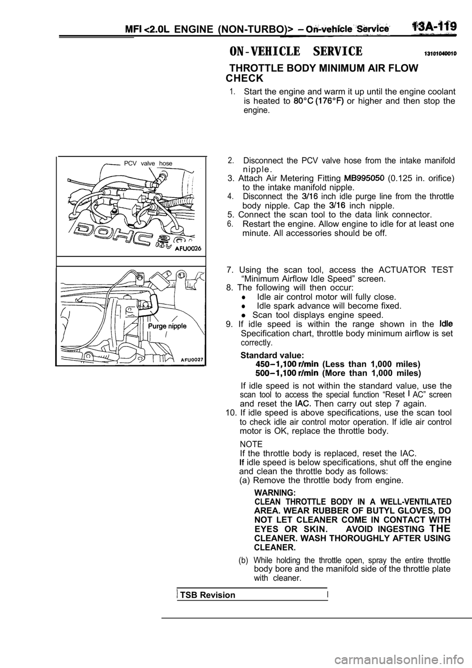
PCV valve hose2.Disconnect the PCV valve hose from the intake manif old
n i p p l e .
3. Attach Air Metering Fitting
(0.125 in. orifice)
to the intake manifold nipple.
4.Disconnect the inch idle purge line from the throttle
body nipple. Cap the inch nipple.
5. Connect the scan tool to the data link connector .
6.Restart the engine. Allow engine to idle for at least one
minute. All accessories should be off.
7. Using the scan tool, access the ACTUATOR TEST “Minimum Airflow Idle Speed” screen.
8. The following will then occur:
lIdle air control motor will fully close.
lIdle spark advance will become fixed.
l Scan tool displays engine speed.
9. If idle speed is within the range shown in the
Specification chart, throttle body minimum airflow is set
correctly.
Standard value:
(Less than 1,000 miles)
(More than 1,000 miles)
If idle speed is not within the standard value, use the
scan tool to access the special function “Reset AC” screen
and reset the Then carry out step 7 again.
10. If idle speed is above specifications, use the scan tool
to check idle air control motor operation. If idle air control
motor is OK, replace the throttle body.
NOTE
If the throttle body is replaced, reset the IAC.
idle speed is below specifications, shut off the e ngine
and clean the throttle body as follows: (a) Remove the throttle body from engine.
WARNING:
CLEAN THROTTLE BODY IN A WELL-VENTILATED
AREA. WEAR RUBBER OF BUTYL GLOVES, DO
NOT LET CLEANER COME IN CONTACT WITH
EYES OR SKIN. AVOID INGESTING THE
CLEANER. WASH THOROUGHLY AFTER USING
CLEANER.
(b) While holding the throttle open, spray the entir e throttle
body bore and the manifold side of the throttle plate
with cleaner.
TSB RevisionI
Page 1009 of 2103
CONTENTS
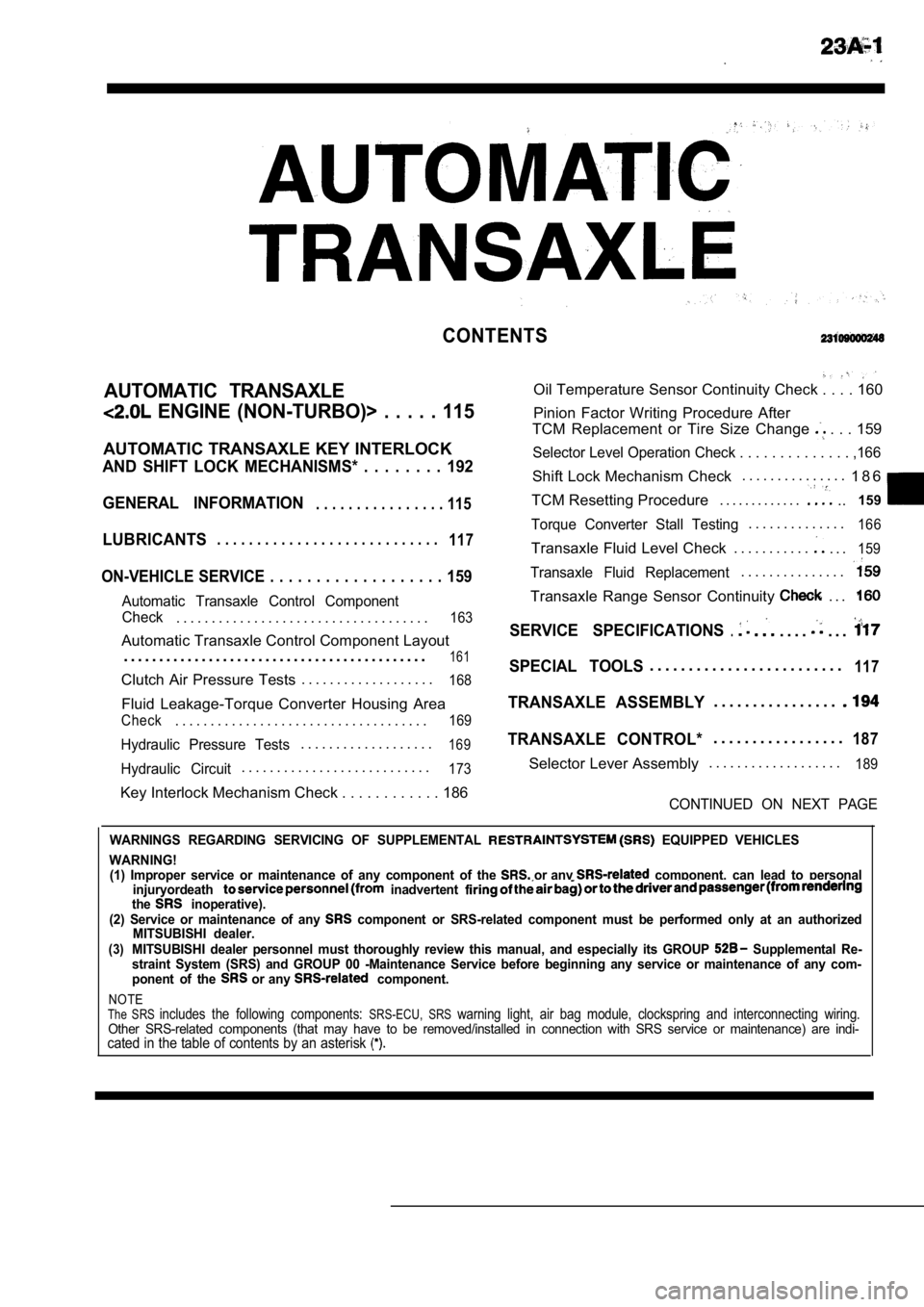
AUTOMATIC TRANSAXLE
ENGINE (NON-TURBO)> . . . . . 115
AUTOMATIC TRANSAXLE KEY INTERLOCK
AND SHIFT LOCK MECHANISMS* . . . . . . . . 192
GENERAL INFORMATION
. . . . . . . . . . . . . . . . 115
LUBRICANTS. . . . . . . . . . . . . . . . . . . . . . . . . . . .117
ON-VEHICLE SERVICE . . . . . . . . . . . . . . . . . . . 159
Automatic Transaxle Control Component
Oil Temperature Sensor Continuity Check . . . . 160
Pinion Factor Writing Procedure After
TCM Replacement or Tire Size Change
. . . 159
Selector Level Operation Check . . . . . . . . . . . . . . ,166
Shift Lock Mechanism Check. . . . . . . . . . . . . . .
1 8 6
TCM Resetting Procedure . . . . . . . . . . . . .
..159
Torque Converter Stall Testing. . . . . . . . . . . . . .166
Transaxle Fluid Level Check . . . . . . . . . . .. . .159
Transaxle Fluid Replacement. . . . . . . . . . . . . . .
Transaxle Range Sensor Continuity . . .
Check. . . . . . . . . . . . . . . . . . . . . . . . . . . . . . . . . . . .163SERVICE SPECIFICATIONS.. . . .. . .Automatic Transaxle Control Component Layout
. . . . . . . . . . . . . . . . . . . . . . . . . . . . . . . . . . . . . . . . . . .
161SPECIAL TOOLS. . . . . . . . . . . . . . . . . . . . . . . . .117Clutch Air Pressure Tests . . . . . . . . . . . . . . . . . . .168
Fluid Leakage-Torque Converter Housing Area
Check. . . . . . . . . . . . . . . . . . . . . . . . . . . . . . . . . . . .169
Hydraulic Pressure Tests. . . . . . . . . . . . . . . . . . .169
Hydraulic Circuit. . . . . . . . . . . . . . . . . . . . . . . . . . .173
TRANSAXLE ASSEMBLY. . . . . . . . . . . . . . . .
TRANSAXLE CONTROL*. . . . . . . . . . . . . . . . .187
Selector Lever Assembly. . . . . . . . . . . . . . . . . . .189
Key Interlock Mechanism Check . . . . . . . . . . .
. 186CONTINUED ON NEXT PAGE
WARNINGS REGARDING SERVICING OF SUPPLEMENTAL EQUIPPED VEHICLES
WARNING! (1) Improper service or maintenance of any componen t of the
or any component, can lead to personal
injuryordeath inadvertent the inoperative).
(2) Service or maintenance of any component or SRS-related component must be perform ed only at an authorized
MITSUBISHI dealer.
(3)MITSUBISHI dealer personnel must thoroughly review this manual, and especially its GROUP Supplemental Re-
straint System (SRS) and GROUP 00 -Maintenance Serv ice before beginning any service or maintenance of any com-
ponent of the
or any component.
NOTEThe SRS includes the following components: SRS-ECU, SRS warning light, air bag module, clockspring and inte rconnecting wiring.Other SRS-related components (that may have to be removed/installed in connection with SRS service or maintenance) are indi-cated in the table of contents by an asterisk
Page 1159 of 2103
AUTOMATIC .
.
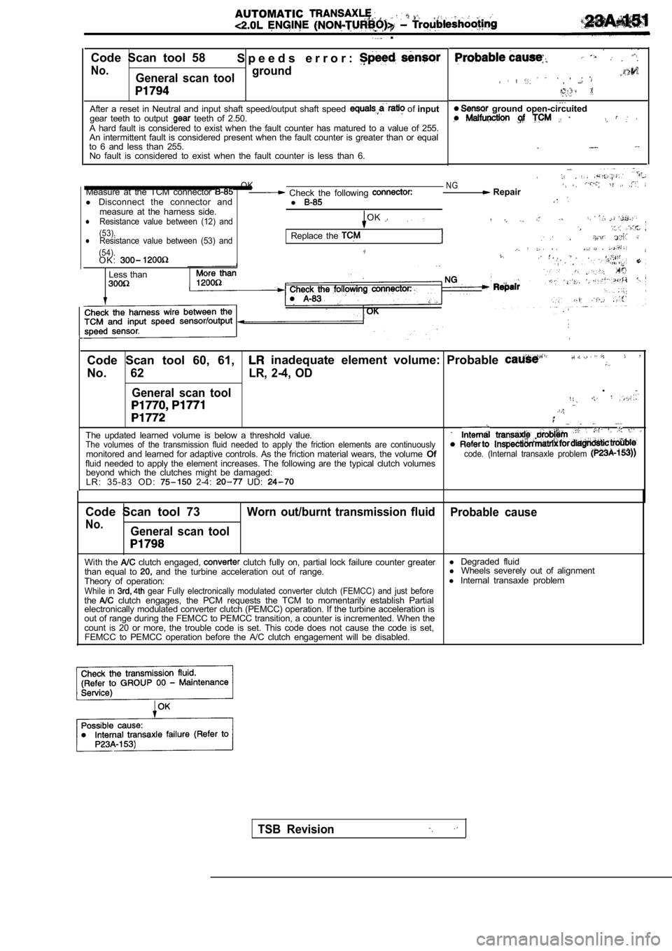
Code Scan tool 58 S p e e d s e r r o r :
No.General scan toolground
After a reset in Neutral and input shaft speed/outp
ut shaft speed of input
gear teeth to output teeth of 2.50.
A hard fault is considered to exist when the fault counter has matured to a value of 255.
An intermittent fault is considered present when th e fault counter is greater than or equal
to 6 and less than 255. No fault is considered to exist when the fault coun ter is less than 6.
.
. , ,
. .
ground open-circuited
OKNGMeasure at the TCM connector Check the following Repair
l Disconnect the connector and
l
measure at the harness side.Resistance value between (12) andOKl
(53).lResistance value between (53) andReplace the . (54).O K :.
Less than
Code Scan tool 60, 61, inadequate element volume: Probable
No. 62LR, 2-4, OD
General scan tool
.
The updated learned volume is below a threshold val ue..The volumes of the transmission fluid needed to app
ly the friction elements are continuouslymonitored and learned for adaptive controls. As the friction material wears, the volume Ofcode. (Internal transaxle problem fluid needed to apply the element increases. The fo llowing are the typical clutch volumes
beyond which the clutches might be damaged:
L R : 3 5 - 8 3 O D :
2-4: UD:
Code Scan tool 73Worn out/burnt transmission fluid Probable cause
No.General scan tool
With the clutch engaged, clutch fully on, partial lock failure counter greaterl
Degraded fluid
than equal to and the turbine acceleration out of range. l
Wheels severely out of alignment
Theory of operation: l
Internal transaxle problem
While in gear Fully electronically modulated converter clut ch (FEMCC) and just beforethe clutch engages, the PCM requests the TCM to moment arily establish Partial
electronically modulated converter clutch (PEMCC) o peration. If the turbine acceleration is
out of range during the FEMCC to PEMCC transition, a counter is incremented. When the
count is 20 or more, the trouble code is set. This code does not cause the code is set,
FEMCC to PEMCC operation before the A/C clutch enga gement will be disabled.
TSB Revision
Page 1167 of 2103
AUTOMATIC TRANSAXLE
ENGINE (NON-TURBO)>
.
to GROU’P 00
RefertoGROUP 00 Maintenance Service.
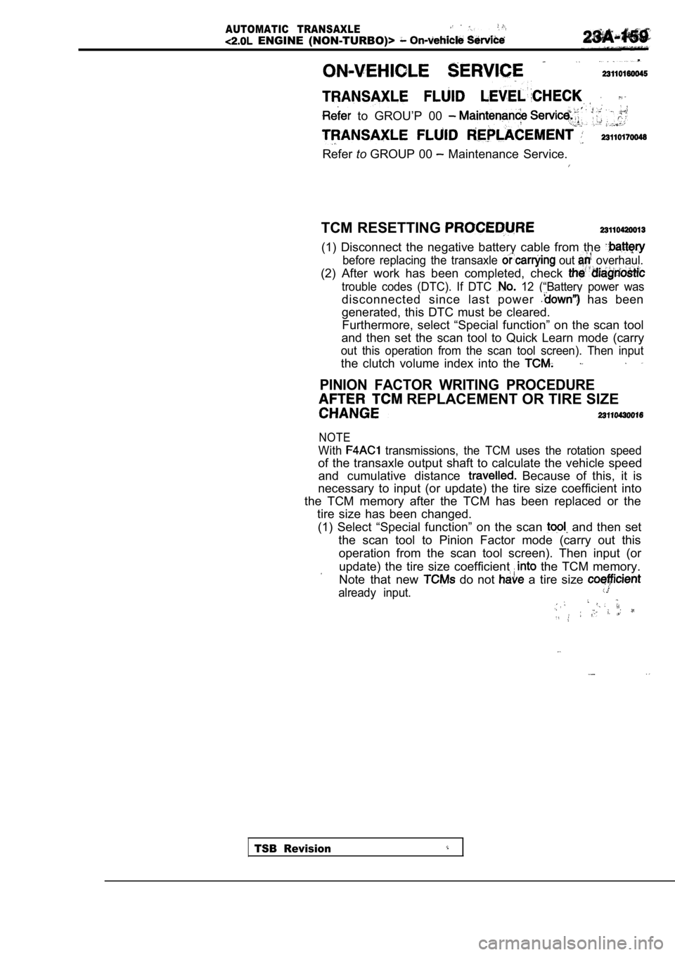
TCM RESETTING
(1) Disconnect the negative battery cable from the
before replacing the transaxle out overhaul.
(2) After work has been completed, check
trouble codes (DTC). If DTC 12 (“Battery power was
disconnected since last power has been
generated, this DTC must be cleared. Furthermore, select “Special function” on the scan tool
and then set the scan tool to Quick Learn mode (car ry
out this operation from the scan tool screen). Then input
the clutch volume index into the
PINION FACTOR WRITING PROCEDURE
REPLACEMENT OR TIRE SIZE
NOTE
With transmissions, the TCM uses the rotation speed
of the transaxle output shaft to calculate the vehicle speed
and cumulative distance
Because of this, it is
necessary to input (or update) the tire size coeffi cient into
the TCM memory after the TCM has been replaced or t he
tire size has been changed.
(1) Select “Special function” on the scan
and then set
the scan tool to Pinion Factor mode (carry out this operation from the scan tool screen). Then input (o r
update) the tire size coefficient the TCM memory.
Note that new
do not a tire size
already input.
TSB Revision
Page 1177 of 2103
AUTOMATIC TRANSAXLE
ENGINE (NON-TURBO)> On-vehicle .
FLUID LEAKAGE-TORQUE CONVERTER
HOUSING AREA CHECK
(1) Check for source of leakage.Since fluid leakage at or around the torque convert er
area may originate from an engine oil leak, the area should
be examined closely, Factory fill fluid is dyed red and,
therefore, can be distinguished from engine oil.
(2) Before removing the transaxle, perform the foll owing
checks:
When leakage is determined to originate from the tr ans-
axle, check fluid level before removal of the transaxle
and torque converter.
High oil level can result in oil leakage out the vent in
the manual shaft. If the fluid level is high, adjust to
proper level.
After fluid is at the proper level, check for leakage. If
a leak
perform the following operation on the
to determine if it is the torque converter or tran saxle
that is, leaking.
TORQUE CONVERTER LEAKAGE
Possible sources of torque converter leakage are:
(2) Torque converter weld leaks at the out side (pe ripheral)
weld. Torque converter hub weld.
(3) Hub
inside and not visible. Do not attempt to
repair.
Replace torque converter.
If the torque converter must be replaced, refer to Torque
Converter Clutch Break-in Procedure in this section . This
procedure’ will reset the transaxle control module break-in
status. Failure to perform this procedure may cause transaxle
shutter.
Clutch
HYDRAULIC PRESSURE TESTS
Pressure testing is a very important step in the diagnostic
procedure. These tests usually reveal the cause of most
transaxle problems.
Before performing pressure tests, be certain that fluid level
and condition, and shift cable adjustments have bee n checked
and approved.Fluid must be at operating temperature
(150 to
1. Install an engine tachometer.
2.Raise vehicle on hoist which allows front wheels to
turn,
and position tachometer so it can be read.
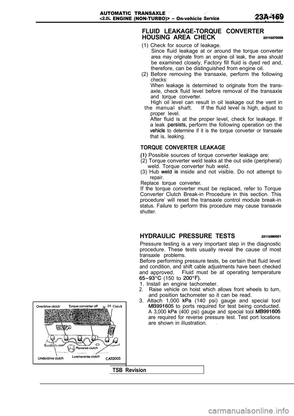
3. Attach 1,000
(140 psi) gauge and special tool
to ports required for test being conducted.
A 3,000 (400 psi) gauge and special tool
are required for reverse pressure test. Test port l ocations
are shown in illustration.
TSB Revision
Page 1605 of 2103
FRONT SUSPENSION On-vehicle Service
NOTE .
1.If the toe-in is not standard value, adjust the
toe-in by undoing, the and the left arid
tie rod by the same amount (in opposite direc-
tions).
2. The toe will move out as the is turned
toward the front of the vehicle and the
is turned toward the rear of the vehicle.
STEERING ANGLE
Standard value:
Inner wheel
(AWD)
Outer wheel
(FWD)
(AWD)
CAMBER
Standard value:
(Vehicles with lbinch wheels)
(Vehicles with wheels),AWD
CASTER
Standard value:
NOTE
1.Camber and caster are preset at the’factory and can not
be adjusted.
2. If camber is not within the standard value, chec k
replace bent or damaged parts.
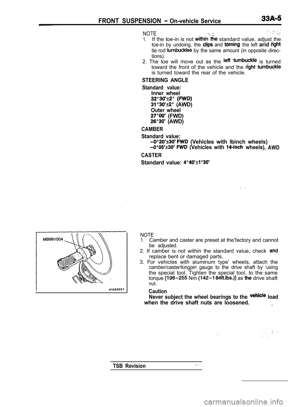
3. For vehicles with aluminum type’ wheels, attach the
camber/caster/kingpin gauge to the drive shaft by ‘using
the special tool. Tighten the special tool, to the same
torque
Nm as drive shaft
nut.
Caution
Never subject the wheel bearings to the load
when the drive shaft nuts are loosened.
TSB Revision