Page 781 of 2103
ENGINE AND EMISSION CONTROL
Engine (Non-turbo)> (Turbo) and
Powertrain control module removal
steps Engine (Non-turbo)>
l Air cleaner22. Powertrain control module bracket23. Powertrain control module
Auto-cruise removalsteps Engine (Turbo) and Engine>
l side
Auto-cruise control main switch
removat steps
25. Instrument panel switch 26. Auto-cruise control main
TSB Revision
Page 838 of 2103
21CLUTCH Clutch Pedal
CLUTCH PEDAL
REMOVAL AND INSTALLATION
Pre-removal OperationlScuff Plate Removal GROUP Cowl Side Trim Removal(Refer to GROUP Trims.)
l Junction Block Installation Boll: Removal
Post-installation Operationl Clutch Pedal Adjustment (Refer tol Junction Block Installation
l Cowl Side Trim Installation (Refer to GROUP Trims.) Scuff Plate Installation
(Refer to GROUP Trims.)
I
I
Nm7-929 Nm21
5
Removal steps
1. Instrument under
(Refer to GROUP Panel.)
2. Master cylinder installation nuts
3. Clutch pedal return spring gine (Non-turbo) Engine>4. Clevis pin
5. Clutch pedal assembly
6. Clevis pin
(Turbo)>
7. Rod A Engine (Turbo)>
8. Turnover spring Engine
9. Rod Engine (Turbo)>
Revision
00003519
E n g i n e ( T u r b o ) >
Clutch pedal13. Bushing
14. Spacer
15. Pedal pad
16. Adjusting bolt
17. Clutch pedal position switch
18. Interlock switch
19. Clutch pedal bracket assembly
Page 1106 of 2103

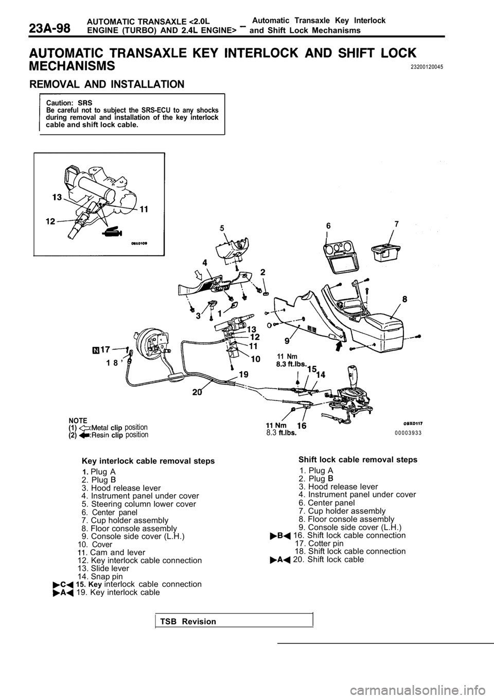
AUTOMATIC TRANSAXLE Automatic Transaxle Key Interlock
ENGINE (TURBO) AND ENGINE> and Shift Lock Mechanisms
23200120045
REMOVAL AND INSTALLATION
Caution:Be careful not to subject the SRS-ECU to any shocksduring removal and installation of the key interlockcable and shift lock cable.
567
I
- -
1 8 ’
NOTE(1) clip
(2) clipposition position
Key interlock cable removal steps
1. Plug A
2. Plug
3. Hood release lever
4. Instrument panel under cover
5. Steering column lower cover
6. Center panel7. Cup holder assembly
8. Floor console assembly9. Console side cover (L.H.)
10. Cover Cam and lever
12. Key interlock cable connection
13. Slide lever
14. Snap pin
15. Key interlock cable connection 19. Key interlock cable
11 Nm
8.30 0 0 0 3 9 3 3
Shift lock cable removal steps 1. Plug A
2. Plug
3. Hood release lever
4. Instrument panel under cover
6. Center panel
7. Cup holder assembly
8. Floor console assembly
9. Console side cover (L.H.)
16. Shift lock cable connection
17. Cotter pin
18. Shift lock cable connection
20. Shift lock cable
TSB Revision
Page 1198 of 2103

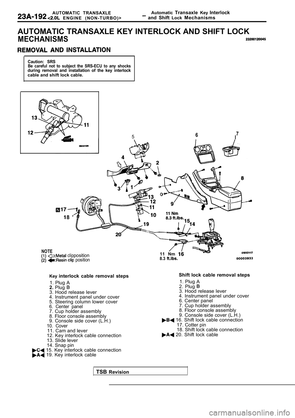
AUTOMATIC TRANSAXLE
E N G I N E ( N O N - T U R B O ) >Automatic
Transaxle KeyInterlock and Shift LockMechanisms
AUTOMATIC TRANSAXLE KEY INTERLOCK AND SHIFT LOCK
MECHANISMS
Caution: SRSBe careful not to subject the SRS-ECU to any shocksduring removal and installation of the key interloc kcable and shift lock cable.
NOTE
567I
8 ’
clipposition position
Key
interlock cable removal steps
1. Plug A
2. Plug
3. Hood release lever
4. Instrument panel under cover
5. Steering column lower cover
6. Center panel7. Cup holder assembly
8. Floor console assembly
9. Console side cover (L.H.)
10. Cover11. Cam and lever
12. Key interlock cable connection
13. Slide lever
14. Snap pin
15. Key interlock cable connection 19. Key interlock cable 11 Nm
8.3
Shift lock cable removal steps
1. Plug A
2. Plug
3. Hood release lever
4. Instrument panel under cover 6. Center panel
7. Cup holder assembly
8. Floor console assembly
9. Console side cover (L.H.)
16. Shift lock cable connection
17. Cotter pin
18. Shift lock cable connection
20. Shift lock cable
TSB Revision
Page 1955 of 2103
E X T E R I O R D o o r
DOOR MIRROR
SPECIAL TOOL
ToolTool number and name
O r n a m e n t r e m o v e r
DOOR MIRROR
REMOVAL INSTALLATION
controlled mirror>
1
Door mirror removal steps
lDoor trim (Refer to GROUP 42 Door
Trim and Waterproof Film.)
1. Knob
2. Delta cover inner
3. Boot
.
Door mirror control switch removalsteps
6. Instrument panel switch assembly 7. Door mirror control switch
TSB Revision .
Page 1959 of 2103

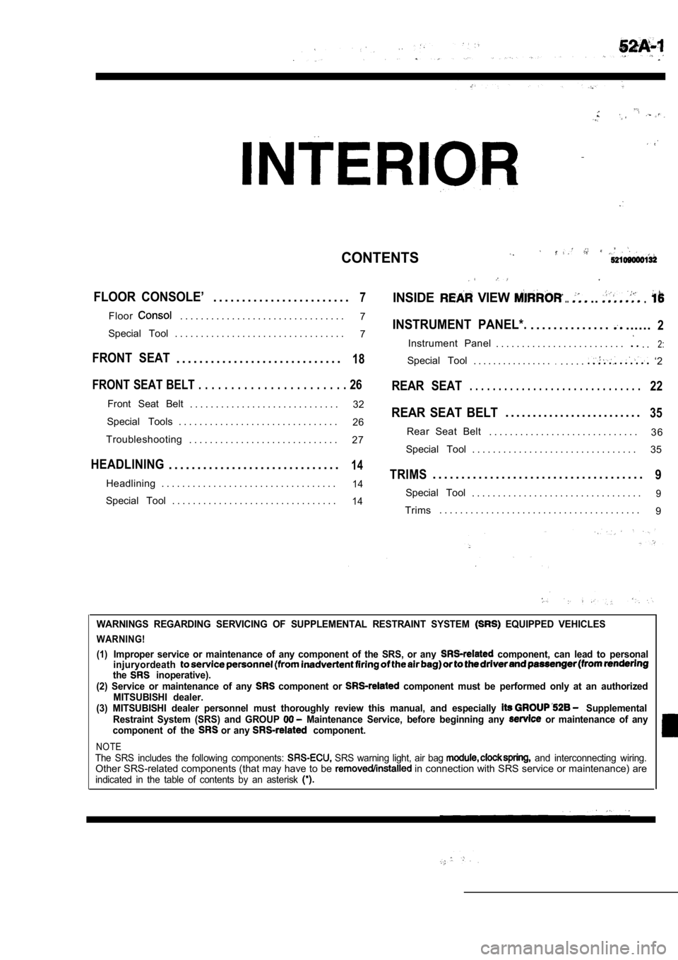
CONTENTS
FLOOR CONSOLE’. . . . . . . . . . . . . . . . . . . . . . . .7INSIDE VIEW .....
Floor. . . . . . . . . . . . . . . . . . . . . . . . . . . . . . . .7INSTRUMENT PANEL*.. . . . . . . . . . . . . .......2Special Tool . . . . . . . . . . . . . . . . . . . . . . . . . . . . . . . . . 7
Instrument Panel . . . . . . . . . . . . . . . . . . . . . . . . .. .2:
FRONT SEAT. . . . . . . . . . . . . . . . . . . . . . . . . . . . .18Special Tool. . . . . . . . . . . . . . . ... . . . .. ‘2
FRONT SEAT BELT . . . . . . . . . . . . . . . . . . . . . . . 26REAR SEAT. . . . . . . . . . . . . . . . . . . . . . . . . . . . . .22
Front Seat Belt
. . . . . . . . . . . . . . . . . . . . . . . . . . . . . 32REAR SEAT BELT. . . . . . . . . . . . . . . . . . . . . . . . .35Special Tools . . . . . . . . . . . . . . . . . . . . . . . . . . . . . . .
26
3 6
Troubleshooting Rear Seat Belt
. . . . . . . . . . . . . . . . . . . . . . . . . . . . .
. . . . . . . . . . . . . . . . . . . . . . . . . . . . . 27
Special Tool . . . . . . . . . . . . . . . . . . . . . . . . . . . . . . . . 35
HEADLINING. . . . . . . . . . . . . . . . . . . . . . . . . . . . . .14TRIMS. . . . . . . . . . . . . . . . . . . . . . . . . . . . . . . . . . . . .9Headlining . . . . . . . . . . . . . . . . . . . . . . . . . . . . . . . . . .14Special Tool. . . . . . . . . . . . . . . . . . . . . . . . . . . . . . . . .9Special Tool . . . . . . . . . . . . . . . . . . . . . . . . . . . . . . . .14Trims. . . . . . . . . . . . . . . . . . . . . . . . . . . . . . . . . . . . . . .
9
WARNINGS REGARDING SERVICING OF SUPPLEMENTAL RESTRA INT SYSTEM EQUIPPED VEHICLES
WARNING!
(1)
Improper service or maintenance of any component of the SRS, or any component, can lead to personal
injuryordeath
the inoperative).
(2) Service or maintenance of any component or component must be performed only at an authorized
MITSUBISHI dealer.
(3) MITSUBISHI dealer personnel must thoroughly rev iew this manual, and especially
Supplemental
Restraint System (SRS) and GROUP Maintenance Service, before beginning any or maintenance of any
component of the or any component.
NOTEThe SRS includes the following components: SRS warning light, air bag and interconnecting wiring.Other SRS-related components (that may have to be in connection with SRS service or maintenance) areindicated in the table of contents by an asterisk
Page 1960 of 2103
INTERIOR Instrument Panel
INSTRUMENT PANEL
.
52100050055
SPECIAL TOOL
ToolTool number and name
General Service tool
Ornament remover
Application
Removal of switch, trim, etc.
INSTRUMENT PANEL52100170154
For installation of the instrument panel, the bolts
and screws described below are used. They are indicated by symbols in the illustration.
Thread diameter
Effective thread length
TSB Revision
Page 1961 of 2103

INTERIOR Instrument Panel
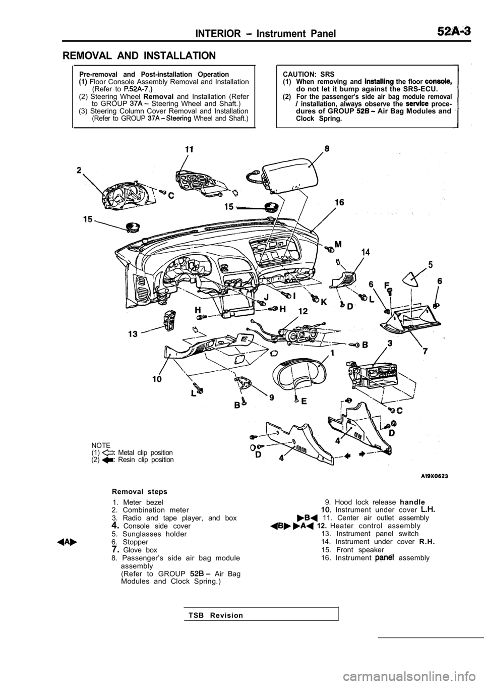
REMOVAL AND INSTALLATION
Pre-removal and Post-installation Operation Floor Console Assembly Removal and Installation(Refer to
(2) Steering Wheel Removaland Installation (Refer
to GROUP Steering Wheel and Shaft.)
(3) Steering Column Cover Removal and Installation
(Refer to GROUP Wheel and Shaft.)
CAUTION: SRS
(1) When removing and the floor do not let it bump against the SRS-ECU.(2)For the passenger’s side air bag module removal installation, always observe the proce-dures of GROUP Air Bag Modules andClock Spring.
14
5
NOTE
(1) Metal clip position
(2) Resin clip position
Removal steps
1. Meter bezel
2. Combination meter
3. Radio and tape player, and box
4. Console side cover
5. Sunglasses holder
6. Stopper 7. Glove box
8. Passenger’s side air bag module assembly(Refer to GROUP
Air Bag
Modules and Clock Spring.)
9. Hood lock release h a n d l e Instrument under cover 11. Center air outlet assembly 12. Heater control assembly
13. Instrument panel switch
14. Instrument under cover R . H .
15. Front speaker
16. Instrument
assembly
T S B R e v i s i o n