Page 1962 of 2103

INTERIOR Instrument Panel
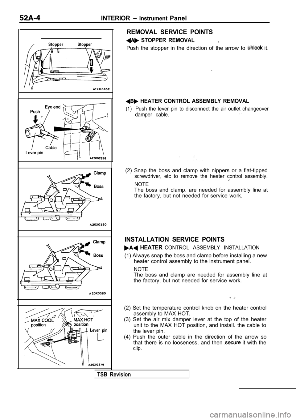
Stopper Stopper
II
A
Lever pin
REMOVAL SERVICE POINTS
STOPPER REMOVAL,
Push the stopper in the direction of the arrow to it.
HEATER CONTROL ASSEMBLY REMOVAL
(1)Push the lever pin to disconnect the air outlet changeover
damper cable..
(2) Snap the boss and clamp with nippers or a flat- tipped
screwdriver, etc to remove the heater control assem bly.
NOTE
The boss and clamp. are needed for assembly line at
the factory, but not needed for service work.
INSTALLATION SERVICE POINTS
HEATER CONTROL ASSEMBLY INSTALLATION
(1) Always snap the boss and clamp before installing a new
heater control assembly to the instrument panel.
NOTE
The boss and clamp are needed for assembly line at
the factory, but not needed for service work.
(2) Set the temperature control knob on the heater control
assembly to MAX HOT.
(3) Set the air mix damper lever at the top of the heater
unit to the MAX HOT position, and install. the cabl e to
the lever pin.
(4) Push the outer cable in the direction of the ar row so
that there is no looseness, and then
it with the
clip.
TSB Revision
Page 1998 of 2103

SRS General Information
GENERAL INFORMATION
INTRODUCTION
The Supplemental Restraint System (SRS) is
signed to supplement the driver’s and front passen-
ger’s seat belts to help reduce the risk or severity
of injury to the driver and front passenger by acti vat-
ing and deploying both air bags in certain frontal
collisions.
The SRS consists of: two air bag modules; one
located in the center of the steering wheel and
another one located above the glove box, which
contains. the folded air bag and an inflator unit;
the SRS air bag control unit (SRS-ECU) located
under the floor console assembly, which monitors
the system, and which contains a safing
sensor
and analog
sensor; an SRS warning light located
on the instrument panel, which indicates the
tional status of the SRS; spring-interconnec-
tion located within the the
It is not until the SRS-ECU in response to the outp ut
signal from the analog sensor, finds it necessary
to ignite the air bag, and the safing sensor is
caused to be ON that the SRS deploys the air
bag.
Only authorized service personnel should do work
on or around SRS components. Those service per-
sonnel should read this manual carefully before
starting any such work. Extreme care must be used
when servicing the SRS, to avoid
to the ser-
vice personnel (by inadvertent deployment of the
air bag) or to driver (by rendering the SRS inopera -
tive).
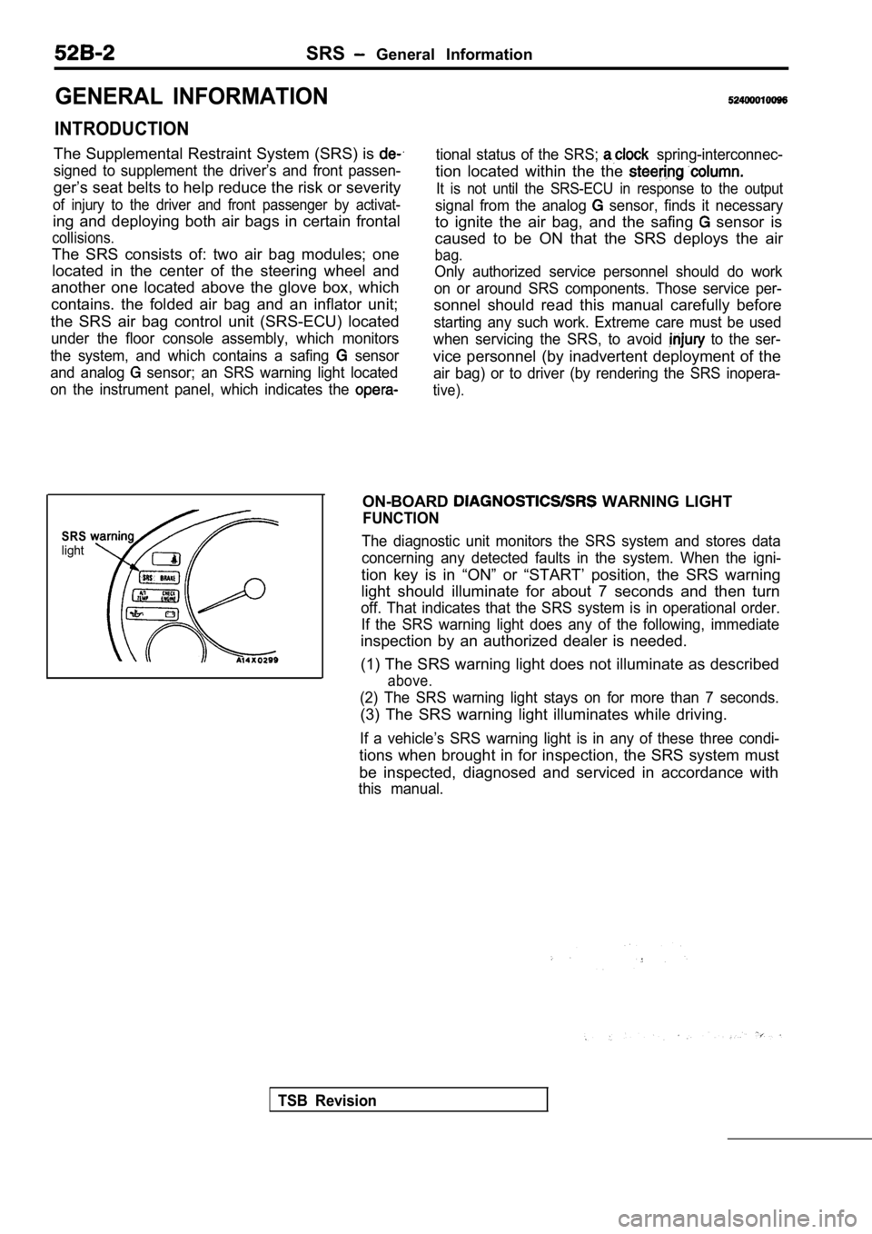
SRSlight
ON-BOARD WARNING LIGHT
FUNCTION
The diagnostic unit monitors the SRS system and sto res data
concerning any detected faults in the system. When the igni-
tion key is in “ON” or “START’ position, the SRS wa rning
light should illuminate for about 7 seconds and the n turn
off. That indicates that the SRS system is in operational order.
If the SRS warning light does any of the following, immediate
inspection by an authorized dealer is needed.
(1) The SRS warning light does not illuminate as de scribed
above.
(2) The SRS warning light stays on for more than 7 seconds.
(3) The SRS warning light illuminates while driving.
If a vehicle’s SRS warning light is in any of these three condi-
tions when brought in for inspection, the SRS syste m must
be inspected, diagnosed and serviced in accordance with
this manual.
TSB Revision
Page 2003 of 2103
SRS General Information
CONFIGURATION DIAGRAMS
D a s h p a n e l
Ignition switch
Air bag module (front passenger’s side)
Data link connector (For scan tool)Data link connector (For scan tool)
Instrument panel
Clock spring
Air bag module (driver’s side)
-18
Combination meter (For warning light)
Combination meter (For SRS warning light)
C-i 8 air bag control unit
TSB Revision
Page 2007 of 2103

SRS Service Precautions
SERVICE PRECAUTIONS52400020092
1. In order to avoid injury to yourself or others
from accidental deployment of the air bag during
servicing, read and carefully follow all the
cautions and procedures described in this
manual.
2. Do not use any electrical test equipment on
or near SRS components, except those
fiedon and
Never use an analog ohmmeter.
3.Never Attempt to Repair the Following
ponents:
SRS Air Bag Control Unit (SRS-ECU)
Clock Spring
Air Bag Module If any of these components are diagnosed as
faulty, they should only be replaced, in
dance with the COMPONENT SERVICE
dures in this manual, starting at page
4. Do not attempt repair the wiring harness
connectors of the SRS. any of the connectors
are diagnosed as faulty, replace the
harness. If the wires are diagnosed asfaulty,
replace or repair the wiring harness according
to the following
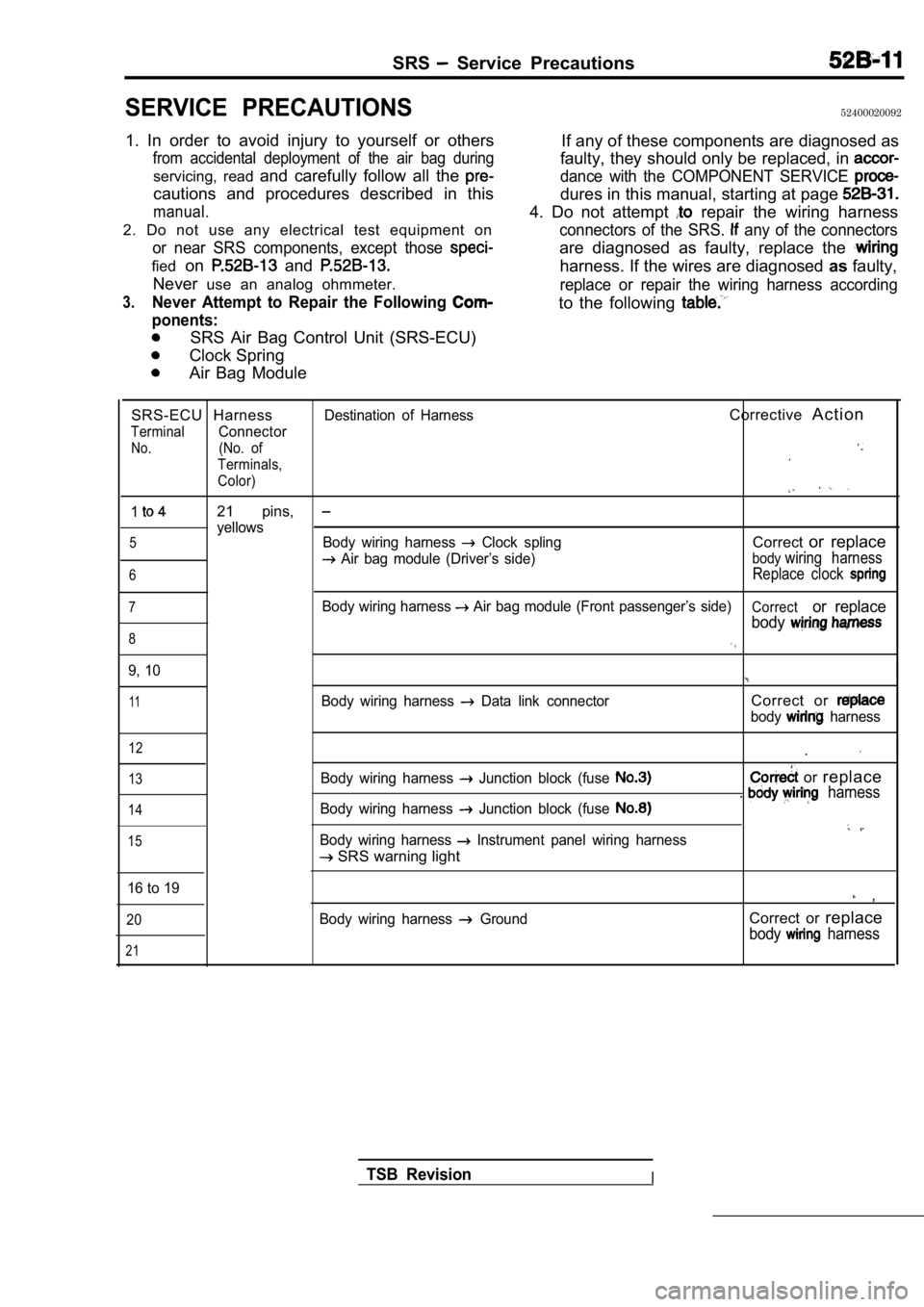
SRS-ECU HarnessDestination of HarnessCorrective A c t i o n
TerminalConnector
No.(No. of
Terminals,
Color)
121 pins,
yellows5Body wiring harness Clock splingCorrector replace
Air bag module (Driver’s side)bodywiring harness
6Replace clock
7Body wiring harness Air bag module (Front passenger’s side)Corrector replace
body
8
9, 10
11Body wiring harness Data link connectorCorrect or
body harness
12
13
14
15
Body wiring harness Junction block (fuse
Body wiring harness Junction block (fuse
Body wiring harness Instrument panel wiring harness
SRS warning light .
or
replace. harness
16 to 19 ,
20
21
Body wiring harness GroundCorrect or replace
body harness
TSB RevisionI
Page 2042 of 2103
55-2
REFRIGERANT LINE. . . . . . . . . . . . . . . . . . . . . .44 OUTLET). .. . . . . . .
SERVICE SPECIFICATIONS. . . . . . . . . . . . . . . . .VENTILATORS* (FLOOR). . . . . . . . . . . . . . . . .
SPECIAL TOOLS. . . . . . . . . . . . . . . . . . . . . . . . . . .5 (INSTRUMENT PANEL) . . .
TROUBLESHOOTING . . . . . . . . . . . . . . . . . . . . . . . 6
Page 2060 of 2103

AIR ,
AND VENTILATION Heater
R E M O V A L
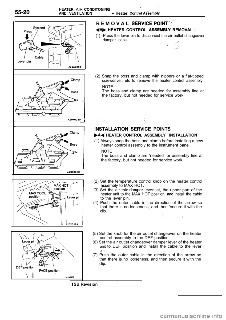
HEATER CONTROL REMOVAL
(1)Press the lever pin to disconnect the air outlet changeover
damper cable.
(2) Snap the boss and clamp with nippers or a flat- tipped
screwdriver, etc to remove the heater control assem bly.
NOTE
The boss and clamp are needed for assembly line at
the factory, but not needed for service work.
INSTALLATION SERVICE POINTS
HEATER CONTROL ASSEMBLY INSTALLATION
(1) Always snap the boss and clamp before installin g a new
heater control assembly to the instrument panel.
NOTE
The boss and clamp are ‘needed for assembly line at
the factory, but not needed for service work.
(2) Set the temperature control knob on the heater control
assembly to MAX HOT.
(3) Set the air mix
lever. at, the upper part of the
heater unit to the MAX HOT position, install the cable
to the lever pin.
(4) Push the outer cable in the direction of the ar row so
that there is no looseness, and then ‘secure it wit h the
clip.
,
(5) Set the knob for the air outlet changeover on the heater
control assembly to the DEF position.
(6) Set the air outlet changeover damper lever of t he heater
unit to DEF position and install the cable to the lever
pin.
(7) Push the outer cable in the direction of the ar row so
that there is no looseness, and then secure it with the
clip.
TSB Revision
Page 2064 of 2103
HEATER, AIR
AND VENTILATION Heater Unit and Heater Core
HEATER UNIT AND HEATER CORE
REMOVAL AND INSTALLATION
Post-installation OperationRefilling CoolantWhen and installing the floor console from vehicles equipped with SRS, do notlet it bump against the ECU or the components.
TSB Revision
Removal steps
l Instrument panel (Refer to GROUP
Instrument Panel.)1. Heater hose connection2. Center stay
3. Center duct
4. Semi rear heater duct
5. Foot distribution duct
6. Cooling unit installation bolt and nut
7 . C l i p
8. Heater unit
9. Heater core
Page 2066 of 2103
HEATER, AIR
AND VENTILATION Blower Assembly, and Resistor
BLOWER ASSEMBLY AND RESISTOR
REMOVAL AND INSTALLATION
When and installing the floor console as-
Resistor removal steps
1. Stopper2. Resistor
Blowerfan and motor removalsteps
3. Automatic compressor-ECM with A/C for non-turbo>
4. Blower fan and motor
8
Blower unit removal steps
5. Instrument panel (Refer to GROUP Instrument Panel) 6 . C l i p
7. Joint duct without 8.unit installation bolts and
nuts with 9. Blower unit assembly
TSB Revision