1989 MITSUBISHI GALANT oil temperature
[x] Cancel search: oil temperaturePage 207 of 1273
FUEL SYSTEM
(1) Improper adjustment of the basic idling speed.
(2) Deposits adhering to the ttirottle valve.
(3) Air being taken into the intake manifold due to a gasket leak, etc.
OPERATION
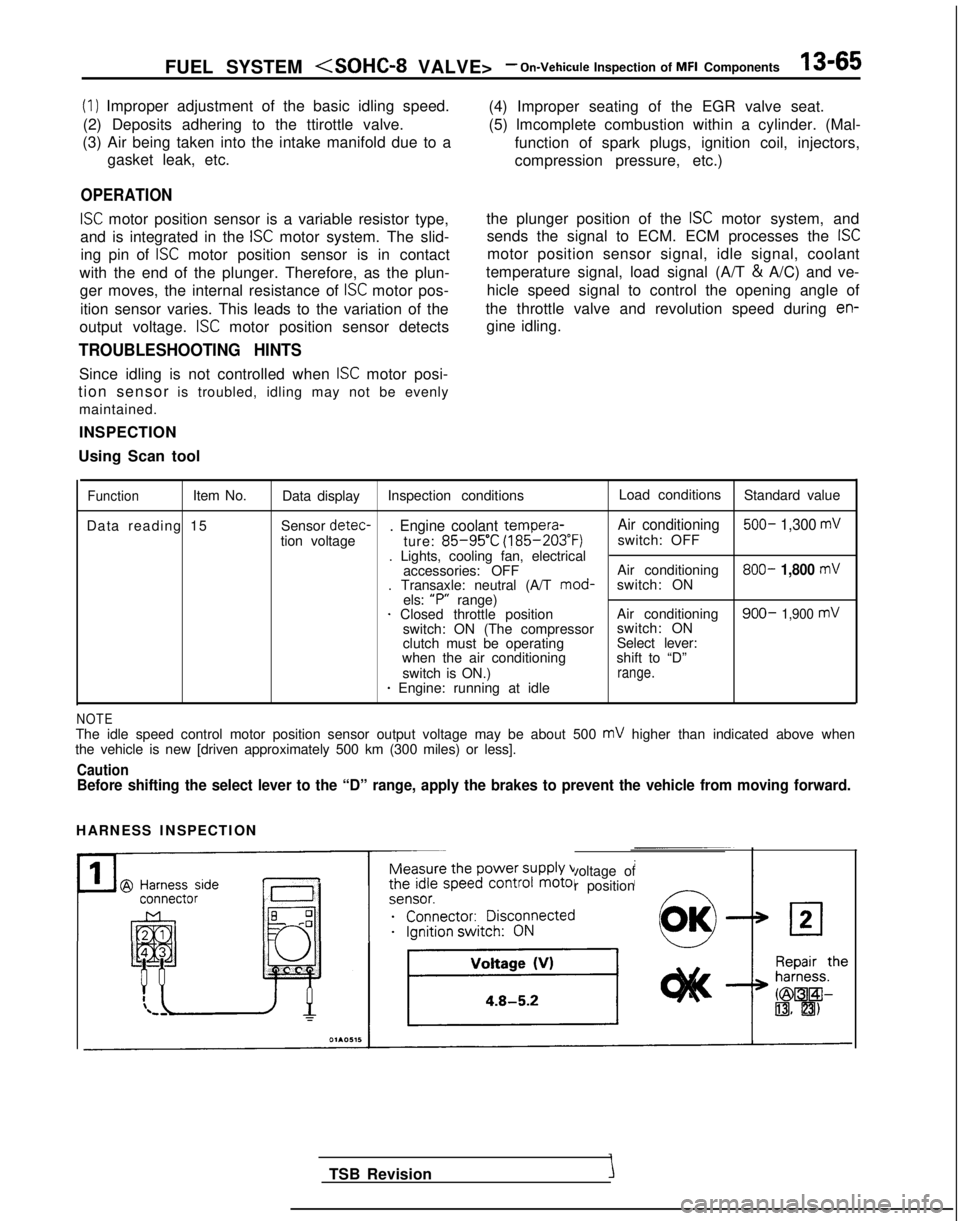
ISC motor position sensor is a variable resistor type,
and is integrated in the
ISC motor system. The slid-
ing pin of
ISC motor position sensor is in contact
with the end of the plunger. Therefore, as the plun- ger moves, the internal resistance of
ISC motor pos-
ition sensor varies. This leads to the variation of the (4) Improper seating of the EGR valve seat.
(5) lmcomplete combustion within a cylinder. (Mal-
function of spark plugs, ignition coil, injectors,
compression pressure, etc.)
the plunger position of the
ISC motor system, and
sends the signal to ECM. ECM processes the
ISC
motor position sensor signal, idle signal, coolant
temperature signal, load signal (A/T &
A/C) and ve-
hicle speed signal to control the opening angle of
the throttle valve and revolution speed during
en-
output voltage. ISC motor position sensor detects gine idling.
TROUBLESHOOTING HINTS
Since idling is not controlled when ISC motor posi-
tion sensor is troubled, idling may not be evenly
maintained.
INSPECTION
Using Scan tool
FunctionItem No. Data display Inspection conditions Load conditions
Standard value
Data reading 15 Sensor detec-
. Engine coolant tempera-
Air conditioning 500- 1,300 mV
tion voltage
ture: 85-95’C (185-203°F)
switch: OFF
. Lights, cooling fan, electrical accessories: OFF Air conditioning 800-
1,800 mV. Transaxle: neutral (A/T
mod-
switch: ON
els: “P”
range)
1 Closed throttle position Air conditioning900- 1,900 mVswitch: ON (The compressorswitch: ON
clutch must be operating Select lever:
when the air conditioning shift to “D”
switch is ON.)
range.* Engine: running at idle
NOTEThe idle speed control motor position sensor output voltage may be about\
500 mV higher than indicated above when
the vehicle is new [driven approximately 500 km (300 miles) or less].
CautionBefore shifting the select lever to the “D” range, apply the brake\
s to prevent the vehicle from moving forward.
HARNESS INSPECTION
Measure the power supply voltage of
the idle speed control motor position
ei;;;it;;sco$ected
__...._ -.-
TSB Revision
Page 216 of 1273
13-74 FUEL SYSTEM
Hint 4:
If idling is possible even though the crankshaft posi-
tion sensor indicated rpm is a deviation from the standard value, the cause is usually a malfunction of
something other than the crankshaft position sen-
sor.
Examples:
(1) Malfunction of the coolant-temperature sensor.
(2) Malfunction of the idling-speed control motor.
(3) Improper adjustment of the standard idling
speed.
INSPECTION
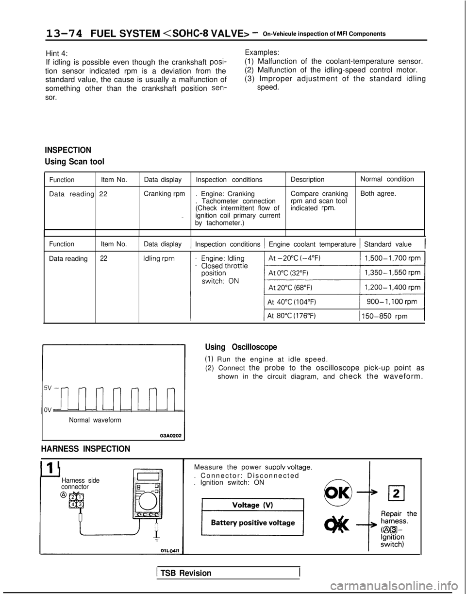
Using Scan tool
FunctionItem No.
Data reading 22 Data display
Inspection conditions DescriptionNormal condition
Cranking rpm . Engine: Cranking Compare crankingBoth agree.
. Tachometer connection rpm and scan tool
(Check intermittent flow of indicated
rpm._ignition coil primary current
by tachometer.)
Function
Data reading Item No.22
Data display1 Inspection conditions 1 Engine coolant temperature 1 Standard value1
1 At 40°C (104°F)1 900-1,100rpm 1
III-I( At 80°C (176°F)1 150-850 rpm
Normal waveform
03AO202
HARNESS INSPECTION
Ilr I
Using Oscilloscope
(1) Run the engine at idle speed.
(2) Connect the probe to the oscilloscope pick-up point as
shown in the circuit diagram, and check the waveform.
Harness side
connector
@
Measure the power SUPPIY voltaoe.
. Connector: Disconnected
-. Ignition switch: ON
1 TSB Revision
Page 261 of 1273
Specifications/Special Tools/FUEL SYSTEM
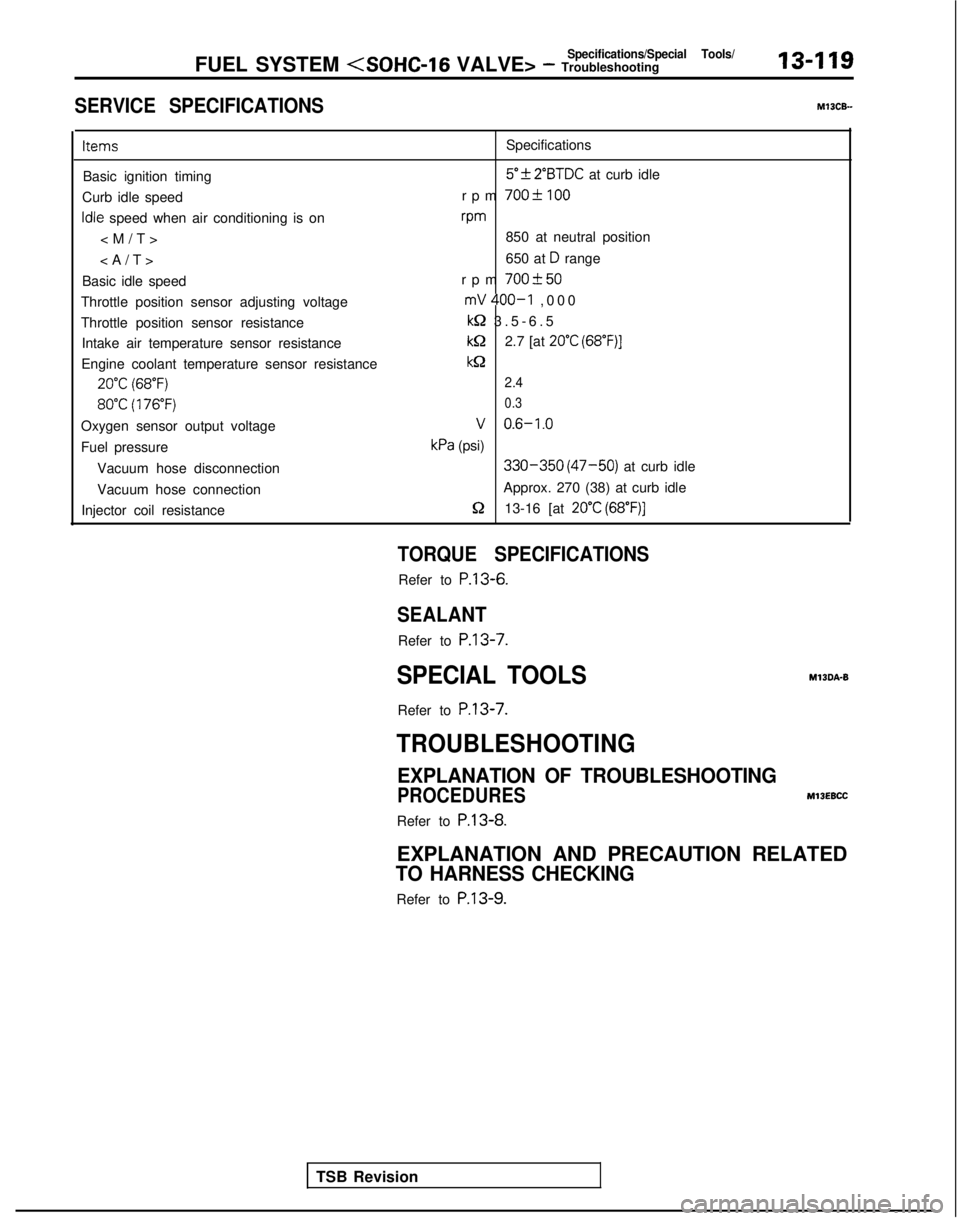
SERVICE SPECIFICATIONS
13-119 MlOCB-
Items
Specifications
Basic ignition timing
5”f 2”BTDC at curb idle
Curb idle speed rpm
700-C 100
Idle speed when air conditioning is onvm
850 at neutral position
650 at
D range
Basic idle speed rpm
700+50
Throttle position sensor adjusting voltagemV 400-I ,00
0
Throttle position sensor resistance
kQ 3.5-6.
5
Intake air temperature sensor resistance
kQ2.7 [at 20°C (68”F)]
Engine coolant temperature sensor resistancekQ
20°C (68°F)2.4
80°C (176°F) 0.3
Oxygen sensor output voltageV 0.6-1.0
Fuel pressurekPa (psi)
Vacuum hose disconnection
330-350 (47-50) at curb idle
Vacuum hose connection Approx. 270 (38) at curb idle
Injector coil resistance
5213-16 [at 20°C (68”F)]
TSB Revision
TORQUE SPECIFICATIONS
Refer to P.13-6.
SEALANT
Refer to
P.13-7.
SPECIAL TOOLS
Refer to
P.13-7.
MlBDA-B
TROUBLESHOOTING
EXPLANATION OF TROUBLESHOOTING
PROCEDURES
MllEBCC
Refer to P.13-8.
EXPLANATION AND PRECAUTION RELATED
TO HARNESS CHECKING
Refer to P.13-9.
Page 264 of 1273
13-122FUEL SYSTEM
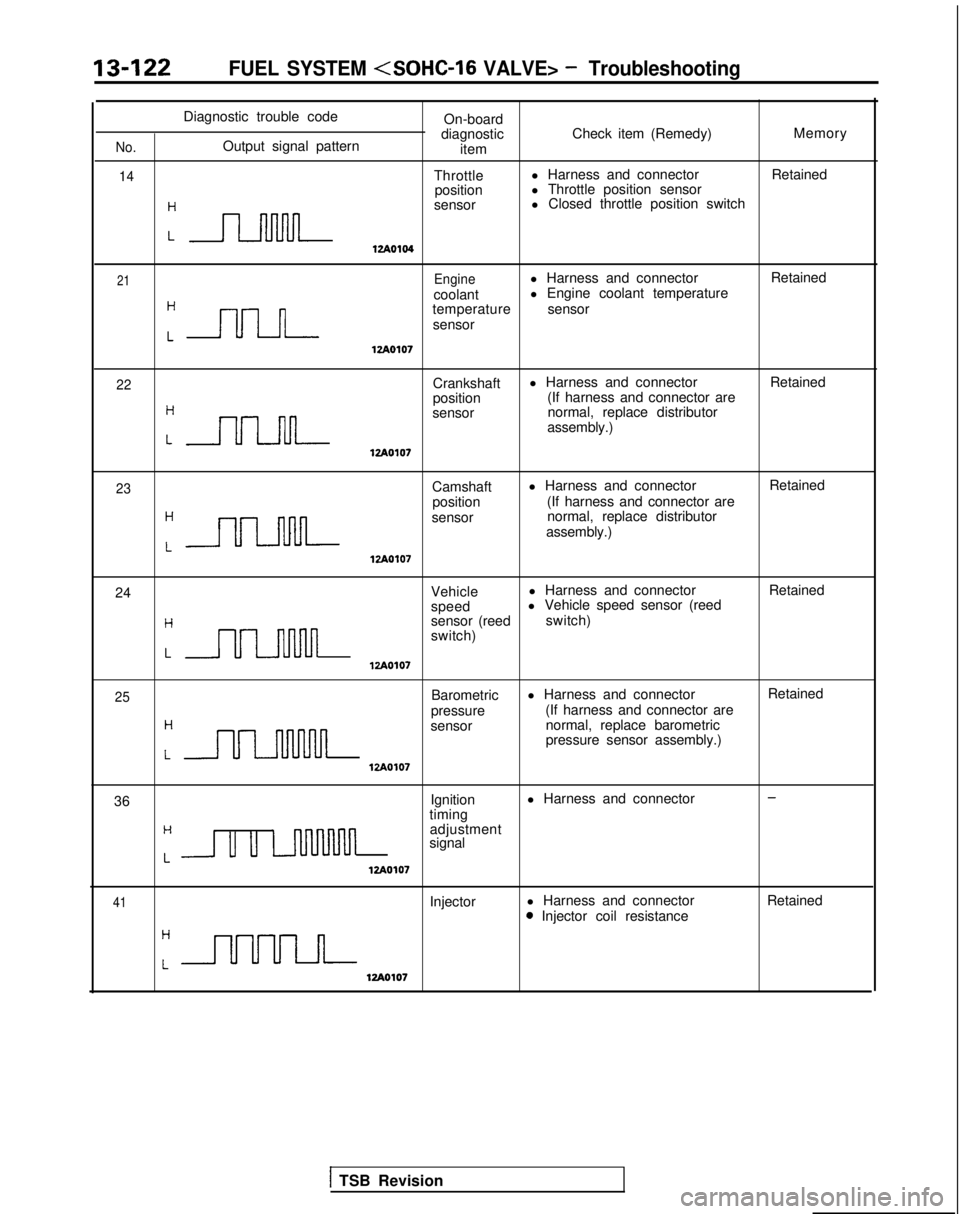
Diagnostic trouble codeOn-board
diagnostic Check item (Remedy) Memory
No.Output signal pattern
item
14Throttlel Harness and connector
Retained
position l Throttle position sensor
:n
sensor l Closed throttle position switch
12Ao104
21Enginel Harness and connector
Retained
coolant l Engine coolant temperature
Cnn
temperature
sensor
sensor
lzAO107
22Crankshaft l Harness and connector
Retained
position (If harness and connector are
:nn
sensor normal, replace distributor
assembly.)
lzAOlO7
23Camshaft l Harness and connector
Retained
position (If harness and connector are
:-
sensor normal, replace distributor
assembly.)
12Ao107
24 Vehiclel Harness and connector
Retained
speed l Vehicle speed sensor (reed
Hsensor (reed
switch)
switch)
LULl-uulnlzAO107
25
H
Barometric
pressure l Harness and connector
(If harness and connector are
LULMlvul
sensor normal, replace barometric
pressure sensor assembly.)
VA0107
Retained
36 Ignition
l Harness and connector
-
timingH
Lu u LnllMnn
adjustment
signal
12Ao107
41Injector l Harness and connector0 Injector coil resistance Retained
12Ao107
1 TSB Revision
Page 269 of 1273
FUEL SYSTEM
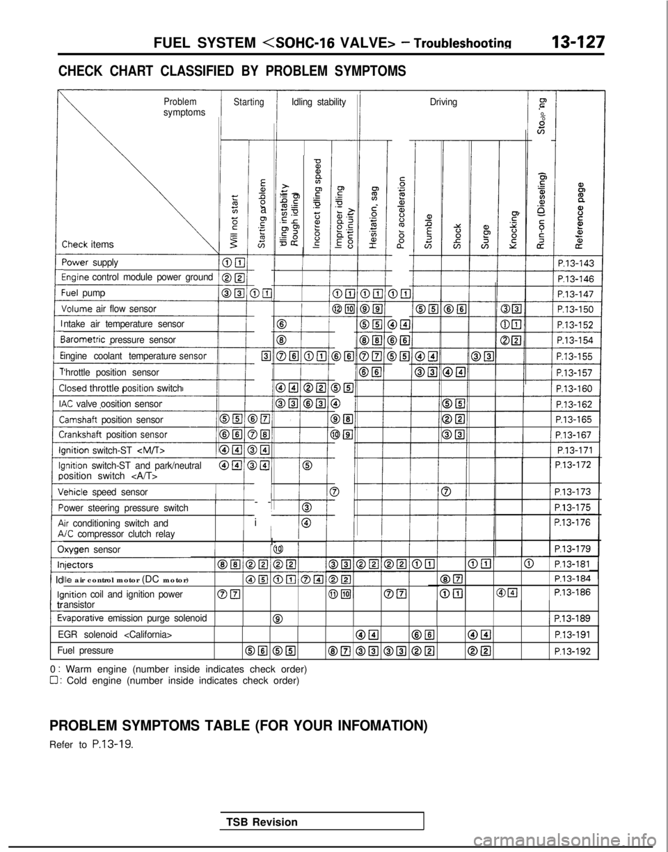
CHECK CHART CLASSIFIED BY PROBLEM SYMPTOMS
ProblemsymptomsStartingIdling stability Drivingr”
.-
%scn
E5
$4.a,o_
5;i
cz
iP.13-143
-
Ea,Ll2a
F.- s
G-
DE-
c-
Elc
-
-
>El
)El-
)I3-
)@I
I-
-
i
-
5‘32a,$%ba”
D&l DEI
i>El
-0%,a>+y -2.gPE.-50 z.E r2?p9 6=& g-
-
-Sheck items
‘ower
supply
%ginecontrol module power groundI
1 P.13-146
:uel pump
Jolume air flow sensor
B
f
E3
DELI @El
cP.13-162
P.13-165III P.13-167I
1/ P.l3-171 1
P.l3-172
P.l3-173
P.l3-175
P.13-176
P.l3-179
ntake air temperature sensor
BIB
DEI
0
DEl
3El
3
-I
iarometric
pressure sensor
ingine coolant temperature
sensor
‘hrottle position sensor
Iosed throttlepositionswitch
K valve oosition sensor
lamshaft position sensor
i-:rankshaft positionsensorIIlnition
switch-ST
-I---0lnition switch-ST and park/neutralosition switch
chicle
speed sensor
ower steering pressure switch
ir conditioning switch and/C compressor clutch relayI/I- IIlxygen sensor
@El@ P.l3-181
@ElP.13-184
@[email protected]
Ile air control motor (DC motor)
inition coil and ignition powerOFI@piJOEIansistor
tiaporative emission purge solenoid01 P.13-189
1 Id
kl
c
tr
t
EGR solenoid
Fuel pressureOIlI @El8E.l @El @El @[email protected]
0 : Warm engine (number inside indicates check order)
0 : Cold engine (number inside indicates check order)
PROBLEM SYMPTOMS TABLE (FOR YOUR INFOMATION)
Refer to P.13-19.
TSB Revision
Page 281 of 1273
FUEL SYSTEM
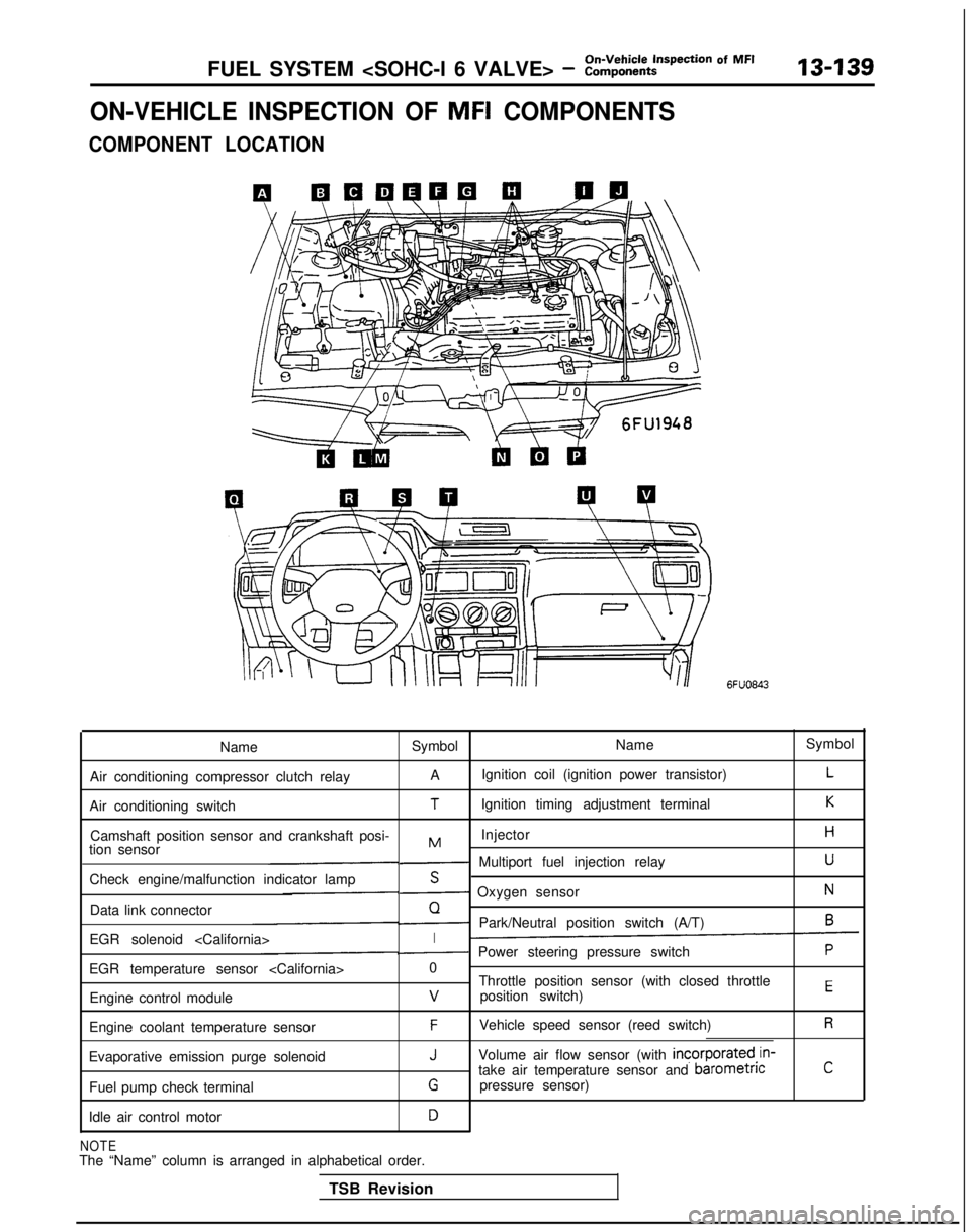
ON-VEHICLE INSPECTION OF MFI COMPONENTS
COMPONENT LOCATION
6FUO843
Name Symbol NameSymbol
Air conditioning compressor clutch relay A
Ignition coil (ignition power transistor)
L
Air conditioning switchTIgnition timing adjustment terminalK
Camshaft position sensor and crankshaft posi- InjectorHMtion sensor- Multiport fuel injection relayU
Check engine/malfunction indicator lampS- Oxygen sensorN
Data link connectorQ- Park/Neutral position switch (A/T)6
EGR solenoid
EGR temperature sensor
Throttle position sensor (with closed throttle
position switch)
EEngine control modulev
Engine coolant temperature sensorFVehicle speed sensor (reed switch)R
Evaporative emission purge solenoidJVolume air flow sensor (with incorporated,in-
take air temperature sensor and barometncC
Fuel pump check terminalGpressure sensor)
Idle air control motor
D
NOTEThe “Name” column is arranged in alphabetical order. TSB Revision
Page 310 of 1273

13-168FUEL SYSTEM
OPERATION
l The crankshaft position sensor detects thecrank angle (piston position) of each cylinder,
converts it to a pulse signal and inputs it to the
engine control module. The engine control mod- ule computes the engine speed and the intake
air amount for one stroke and outputs the injec-
tor drive signal and injection command signal
based on this signal.
0Power to the crankshaft position sensor is sup-
plied from the ignition switch
(IG), and the
ground is located in the engine control module.
A
5V voltage is applied from the engine control
module to the crankshaft position sensor output
terminal, and the crankshaft position sensor generates a pulse signal as it switches from
OPEN to SHORT (power transistor inside the
sensor switches ON/OFF) between the output
terminal and the ground. TROUBLESHOOTING HINTS
Hint
1: If unexpected shocks are felt during driving or the engine stalls suddenly during idling,
shake the crankshaft position sensor har- ness. if this causes the engine to stall, poor
contact of the sensor connector is sus-
pected.
Hint 2: If the crankshaft position sensor outputs a
pulse signal when the ignition switch is
turned to ON, (without starting the engine),
the crankshaft position sensor or engine control module is probably defective.
Hint 3: If the tachometer reads 0 rpm when the en- gine that has failed to start is cranked, faulty
crankshaft position sensor or broken timing
belt is suspected.
Hint 4: If the tachometer reads 0 rpm when the en- gine that has failed to start is cranked, theprimary current of the ignition coil is not
turned on and off. Therefore, troubles in the ignition circuit and ignition coil or faulty igni-
tion power transistor is suspected.
Hint 5: If the engine can be run at idle even though
the crankshaft position sensor reading is out
of specification, troubles are often in other
than the crankshaft position sensor. [Examples]
(1) Faulty water temperature sensor
(2) Faulty idle air control motor
(3) Poorly adjusted basic idle speed
TSB Revision
Page 338 of 1273
13-196FUEL SYSTEM
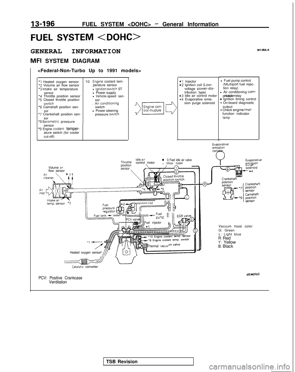
FUEL SYSTEM
GENERAL INFORMATION
MFI SYSTEM DIAGRAMMl
3BA-A
*1 Injector*2 Ignition coil
(Low-
voltage power-drs-
tribution type)
*3 Idle air control motork4 Evaporative emis-
sion purge solenoid l Fuel pump control (Multiport
fuel injec-
tion relay)
l Air conditioning
corm- pressor clutch relay
* Ignition timing control) On-board diagnostic
output
) Check engine/mal-
function indicator
lamp
Engine coolant tem-
perature sensor
l Ignition swatch STl Power supplyl Vehicle-speed sen-sor
. Arr conditioning
switch
l Power steering
pressure
swatch
‘I Heated oxygen sensor ‘10*2
Volume air flow sensor *3
Intake air temperaturesensor‘4 Throttle position sensor *5
Closed throttle position
swrtch *6
Camshaft position sen-
sor “7
Crankshaft position sen-
sor“8 Barometrrc pressure
sensor
‘9 Engine coolant temper-ature switch (for cooler
cut-off)
Evaporatrveemrssion canister
Evaporatrveemlsslo”Idle airThronlecontrol motorl 3 Fast idle air valveI (Wax tvoe)position\Volume air/sensor3flow sensorf \//n,r\l 2 '8
- lnnhnn toll III1 II
II-“,--?% 11 11 EGR,/alveI.l”lll)i
Fuel injectorII
II
Vacuum hose color
G: Green
L: Light blue
I?: RedY: Yellow5: Black
Heated oxygen sensor Thermal
vacuu
a uCatalytrc converter
HMO163PCV: Positive CrankcaseVentilation
TSB Revision