1989 MITSUBISHI GALANT alarm
[x] Cancel search: alarmPage 1008 of 1273
ACTIVE-ELECTRONIC CONTROL SUSPENSION - Troubleshooting 33B-69
Operation
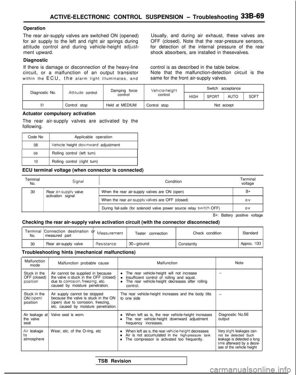
The rear air-supply valves are switched ON (opened)
for air supply to the left and right air springs during
attitude control and during vehicle-height
adjust-
ment upward.
Diagnostic Usually, and during air exhaust, these valves are
OFF (closed). Note that the rear-pressure sensors,
for detection of the internal pressure of the rear shock absorbers, are installed in thesevalves.
If there is damage or disconnection of the heavy-line control is as described in the table below.
circuit, or a malfunction of an output transistor Note that the malfunction-detection circuit is the
within the ECU, the alarm light illuminates, and same for the front air-supply valves.
Switch acceptance
Diagnostic No.
Attrtude control Damping force Vehrcle-height
control controlHIGHSPORTAUTO SOFT
51Control stop Held at MEDIUM
Control stop Not accept
Actuator compulsory activation
The rear air-supply valves are activated by the
following.
Code No Applicable operation
08 Vehicle
height dov/nward adjustment
09 Rolling control (left turn)
10Rolling control (right turn)
ECU terminal voltage (when connector is connected)
Terminal
No.Condition Terminal
voltage
30 Rear alr-supply
valve
activation signal When the rear air-supply valves are ON (open)
B+
When the rear arr-supply valves
are OFF (closed) ov
During fail-safe (for solenoid valve power source relay switch
OFF) ov
B+: Battery positive voltage
Checking the rear air-supply valve activation circuit (with the connect\
or disconnected)
Terminal Connection destination or
MeasurementNo.measured part Tester connection
Check condition
Standard
30 Rear air-supply valve Reststance
30-ground
Troubleshooting hints (mechanical malfunctions)
Constantly
Approx. 1012
Malfunction
mode Malfunction probable cause
MalfunctionNote
Stuck in the Air cannot be supplied in because l
The rear vehicle-height will not increase
-
OFF (closed) the valve IS stuck in the OFF (closed)
l Insufficient control of rolling and squat.posrtion
due to corroson. freezrng,
etc. lThe rear vehicle-height decreases after rolling
caused by moisture penetration. control.
Stuck in the Air supply cannot be stopped The rear vehicle-height increases and the body tilts
-ON (open)
because the valve is stuck in the ON
to one side
position (open) due to corrosion, freezing,
etc. caused by moisture penetration.
Air leakage at Valve seat is worn. lWhen left as is, the rear vehicle-height increases Diagnostic No.56
the valve lThe rear vehicle-height downward adjustment output
seat frequency increases.
Arr leakageW
ear, etc. of the O-ring, etc
lWhen left as
IS, the rear vehrcle-height
decreasesVery slrght leakages can-t
o
lAir is not accumulated in the high-pressure tank not be detected Such
atmosphere lThe compressor is activated too frequently.
leakage is detected a longtrme afterward by a decre-
ase of the vehicle height
TSB Revision
Page 1010 of 1273
ACTIVE-ELECTRONIC CONTROL SUSPENSION - Troubleshooting 33B-71
Operation
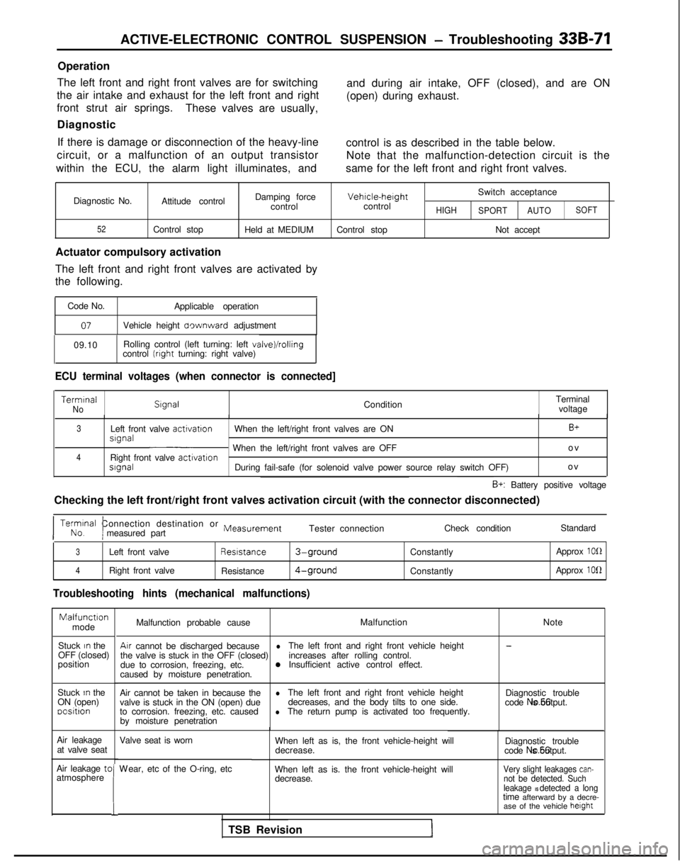
The left front and right front valves are for switching
the air intake and exhaust for the left front and right
front strut air springs. These valves are usually,
Diagnostic and during air intake, OFF (closed), and are ON
(open) during exhaust.
If there is damage or disconnection of the heavy-line control is as described in the table below.
circuit, or a malfunction of an output transistor Note that the malfunction-detection circuit is the
within the ECU, the alarm light illuminates, and same for the left front and right front valves.
Diagnostic No.
52
Damping forceVehicle-herghtSwitch acceptance
Attitude control controlcontrol
HIGH
SPORT AUTOSOFT
Control stop
Held at MEDIUM Control stop Not accept
Actuator compulsory activation
The left front and right front valves are activated by
the following.
Code No. Applicable operation
07Vehicle height aownward adjustment
09.10 Rolling control (left turning: left
valve)/rollingcontrol (rrght turning: right valve)
ECU terminal voltages (when connector is connected] Termrnal
No
Slgnal
ConditionTerminal
voltage
3Left front valve activatron
When the left/right front valves are ONB+srgnal~ When the left/right front valves are OFF o
v
4Right front valve
activatronsrgnalDuring fail-safe (for solenoid valve power source relay switch OFF)
o
v
B+: Battery positive voltage
Checking the left front/right front valves activation circuit (with the\
connector disconnected)
I No. Terminal
Connection destination or
Measurement
Imeasured part Tester connection
Check conditionStandard
3Left front valve Resrstance3-groundConstantly
Approx 1012
4Right front valve
Resistance4-groundConstantly Approx 1012
Troubleshooting hints (mechanical malfunctions)Malfunctron
mode
Stuck
In the
OFF (closed)
position
Stuck
In the
ON (open) oositron
Air leakage at valve seat
Air leakage tc
atmosphere
!
Malfunction probable cause Malfunction
NoteAir
cannot be discharged because
l-
the valve is stuck in the OFF (closed) The left front and right front vehicle height
due to corrosion, freezing, etc. increases after rolling control.0Insufficient active control effect.
caused by moisture penetration.
Air cannot be taken in because the
lvalve is stuck in the ON (open) due The left front and right front vehicle height
Diagnostic trouble
decreases, and the body tilts to one side.
to corrosion. freezing, etc. caused code No.56 is output.lThe return pump is activated too frequently.
by moisture penetration
Valve seat is worn
W
ear, etc of the O-ring, etc
When left as is, the front vehicle-height will
decrease. Diagnostic trouble
code No.56 is output.
When left as is. the front vehicle-height will decrease.
Very slight leakages can-not be detected. Such
leakage IS detected a longtime afterward by a decre- ase of the vehicle height
TSB Revision
Page 1012 of 1273
ACTIVE-ELECTRONIC CONTROL SUSPENSION - Troubleshooting 33B-73
Operation
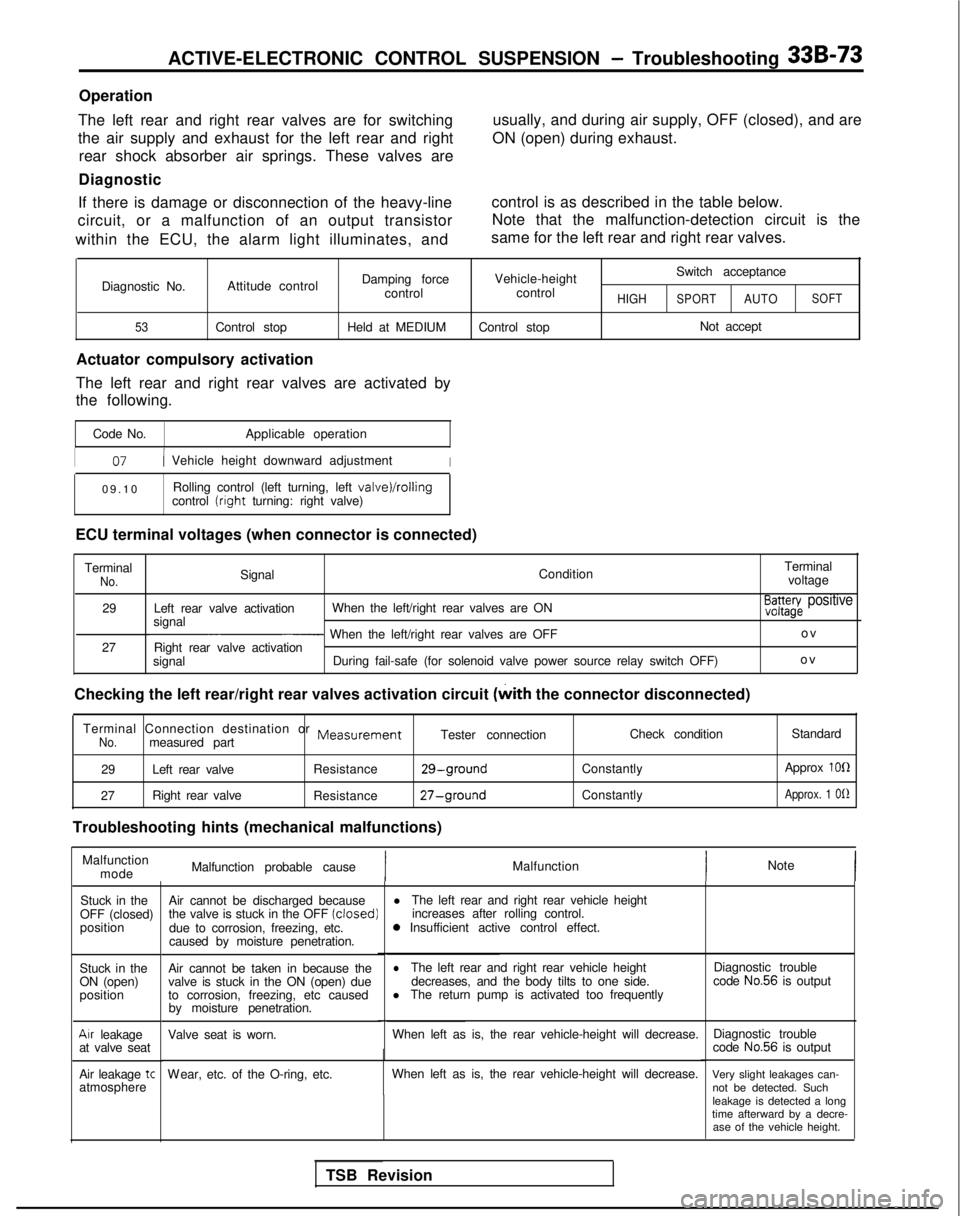
The left rear and right rear valves are for switching
the air supply and exhaust for the left rear and right rear shock absorber air springs. These valves are
Diagnostic usually, and during air supply, OFF (closed), and are
ON (open) during exhaust.
If there is damage or disconnection of the heavy-line
circuit, or a malfunction of an output transistor
within the ECU, the alarm light illuminates, and control is as described in the table below.
Note that the malfunction-detection circuit is the
same for the left rear and right rear valves.
Diagnostic No.
53
Damping force Vehicle-height Switch acceptance
Attitude control controlcontrol
HIGHSPORTAUTOSOFT
Control stop
Held at MEDIUMControl stop Not accept
Actuator compulsory activation
The left rear and right rear valves are activated by
the following.
Code No. Applicable operation
I07/ Vehicle height downward adjustmentI
09.1
0
Rolling control (left turning, left
valve)/rollingcontrol (right
turning: right valve)
ECU terminal voltages (when connector is connected) Terminal
No.Signal ConditionTerminal
voltage
29 Left rear valve activation When the left/right rear valves are ON
signal
E3a3azg~ positive
~ When the left/right rear valves are OFF o
v
27 Right rear valve activation
signal During fail-safe (for solenoid valve power source relay switch OFF) ov
Checking the left rear/right rear valves activation circuit (with
the connector disconnected)
Terminal Connection destination or
MeasurementNo.measured part Tester connection
29 Left rear valve Resistance
29-ground
27Right rear valve
Resistance27-ground
Troubleshooting hints (mechanical malfunctions) Check condition
Constantly
Constantly Standard
Approx
1011
Approx. 1 Of2
Malfunction mode Malfunction probable cause
IMalfunction
Note
Stuck in the
OFF (closed)
position
Stuck in the
ON (open)
position
Air leakage
at valve seat
Air leakage
tcatmosphere Air cannot be discharged because
l
The left rear and right rear vehicle height
the valve is stuck in the OFF (closed)
increases after rolling control.
due to corrosion, freezing, etc. 0
Insufficient active control effect.
caused by moisture penetration.
Air cannot be taken in because the
lThe left rear and right rear vehicle height
valve is stuck in the ON (open) due decreases, and the body tilts to one side.
to corrosion, freezing, etc caused l
The return pump is activated too frequently
by moisture penetration.
Valve seat is worn. When left as is, the rear vehicle-height will decrease.
W
ear, etc. of the O-ring, etc.
When left as is, the rear vehicle-height will decrease.
TSB Revision Diagnostic trouble
code
No.56 is output
Diagnostic trouble
code
No.56 is output
Very slight leakages can- not be detected. Such
leakage is detected a long
time afterward by a decre- ase of the vehicle height.
Page 1026 of 1273
ACTIVE-ELECTRONIC CONTROL SUSPENSIONService Adjustment- Procedures33B-87
Alarm light
With scan tool
Diagnostic check terminal
Serial/
on-board
diagnostic’
outwt
TSB RevisionI
Serial/diagnostic
-switching input
Simulated vehicle-
-speed input
-Ground
16LOO91
!
TOE-IN
Standard value:
Ok3 mm (Of.12 in.)
1. Adjust the toe-in by undoing the clips and turning the left and right tie rod turnbuckles by the same amount (in
opposite directions).
2. The toe will move out as the left turnbuckle
is turned
toward the front of the vehicle and the right turnbuckle is
turned toward the rear of the vehicle.
3.For each half turn of the left and right tie rods, the toe-in will
be adjusted by 6 mm
(.24 in.).
4.After making the adjustments, use a turning radius gage to confirm that the steering wheel turning angle is within the
standard value range. (Refer to GROUP 37A
POWER
STEERING-Service Adjustment Procedures.)
WHEEL BEARING ADJUSTMENT
M33FcAA
Bearing preload is pre-set to the specified value by design and
therefore can not be adjusted.
ALARM LIGHT CHECK
MPFNAC
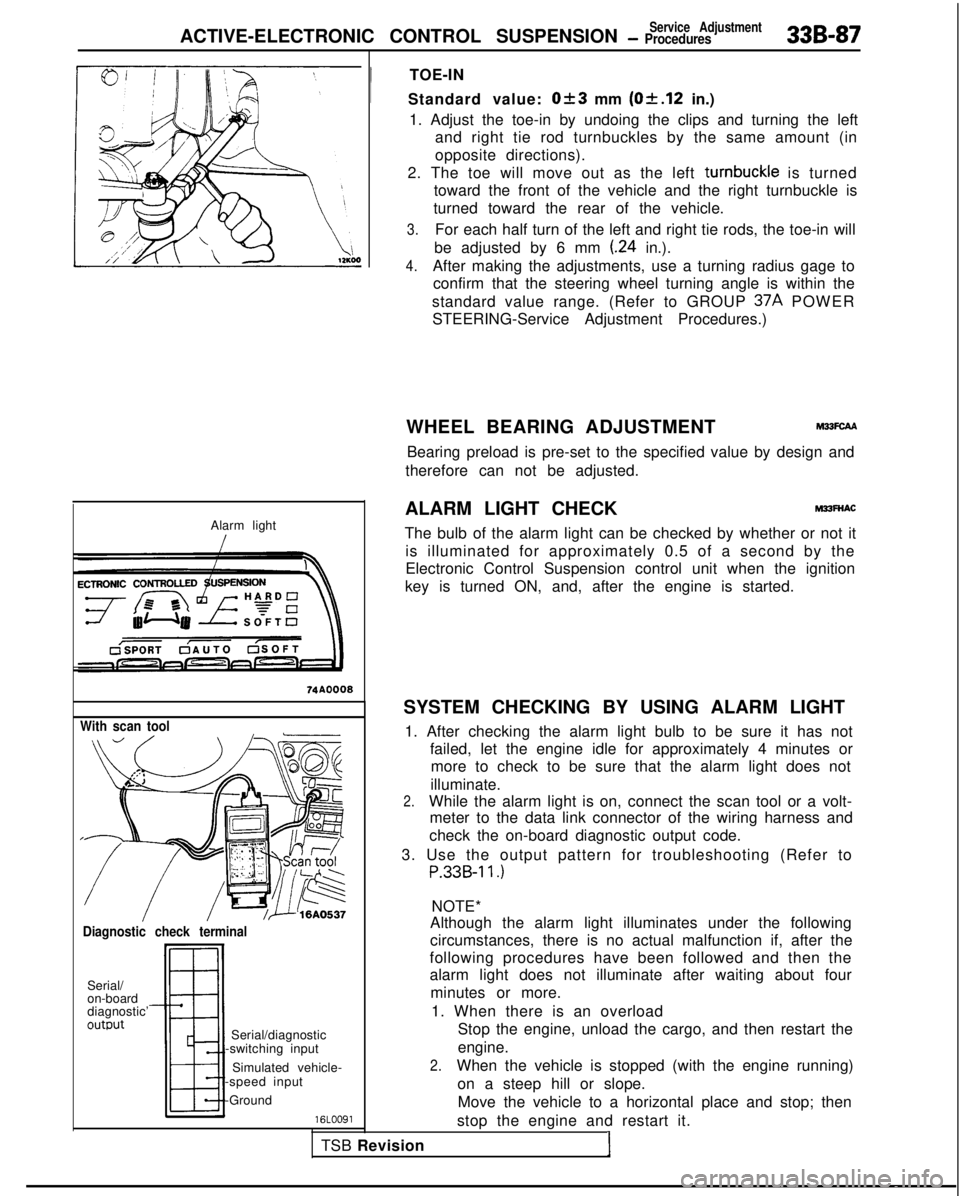
The bulb of the alarm light can be checked by whether or not it is illuminated for approximately 0.5 of a second by the
Electronic Control Suspension control unit when the ignition
key is turned ON, and, after the engine is started.
SYSTEM CHECKING BY USING ALARM LIGHT 1. After checking the alarm light bulb to be sure it has not failed, let the engine idle for approximately 4 minutes ormore to check to be sure that the alarm light does not
illuminate.
2.While the alarm light is on, connect the scan tool or a volt- meter to the data link connector of the wiring harness and
check the on-board diagnostic output code.
3. Use the output pattern for troubleshooting (Refer to
P.33B-11.)
NOTE*
Although the alarm light illuminates under the following
circumstances, there is no actual malfunction if, after the
following procedures have been followed and then the
alarm light does not illuminate after waiting about four
minutes or more.
1. When there is an overload Stop the engine, unload the cargo, and then restart the
engine.
2.When the vehicle is stopped (with the engine running)
on a steep hill or slope.Move the vehicle to a horizontal place and stop; then
stop the engine and restart it.
Page 1027 of 1273
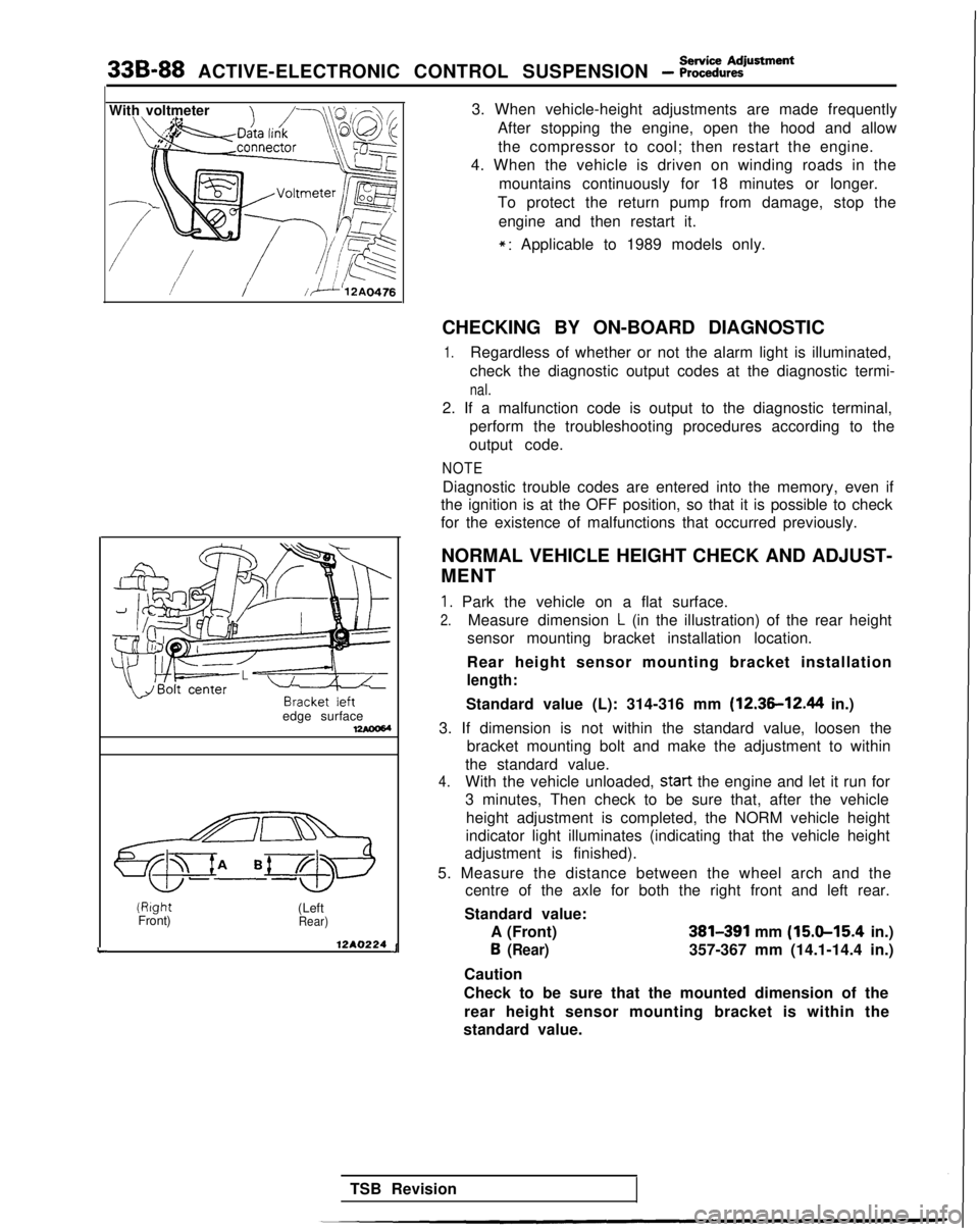
338-88 ACTIVE-ELECTRONIC CONTROL SUSPENSION - ~~~%.,~Rment
With voltmeter
!//ii’12A0476
L
edge surface17AOOW(Right
Front) (Left
Rear)
12A0224 J3. When vehicle-height adjustments are made frequently
After stopping the engine, open the hood and allowthe compressor to cool; then restart the engine.
4. When the vehicle is driven on winding roads in the
mountains continuously for 18 minutes or longer.
To protect the return pump from damage, stop the
engine and then restart it.
*: Applicable to 1989 models only.
CHECKING BY ON-BOARD DIAGNOSTIC
1.Regardless of whether or not the alarm light is illuminated,
check the diagnostic output codes at the diagnostic termi-
nal.
2. If a malfunction code is output to the diagnostic terminal, perform the troubleshooting procedures according to the
output code.
NOTE
Diagnostic trouble codes are entered into the memory, even if
the ignition is at the OFF position, so that it is possible to check
for the existence of malfunctions that occurred previously.
NORMAL VEHICLE HEIGHT CHECK AND ADJUST-
MENT
1. Park the vehicle on a flat surface.
2.Measure dimension L (in the illustration) of the rear height
sensor mounting bracket installation location.
Rear height sensor mounting bracket installation
length:
Standard value (L): 314-316 mm (12.36-12.44 in.)
3. If dimension is not within the standard value, loosen the bracket mounting bolt and make the adjustment to within
the standard value.
4.With the vehicle unloaded, start
the engine and let it run for
3 minutes, Then check to be sure that, after the vehicle
height adjustment is completed, the NORM vehicle height
indicator light illuminates (indicating that the vehicle height
adjustment is finished).
5. Measure the distance between the wheel arch and the centre of the axle for both the right front and left rear.
Standard value: A (Front)
381391 mm (15.9-15.4 in.) 6
(Rear)357-367 mm (14.1-14.4 in.)
Caution
Check to be sure that the mounted dimension of the rear height sensor mounting bracket is within the
standard value.
TSB Revision
Page 1030 of 1273
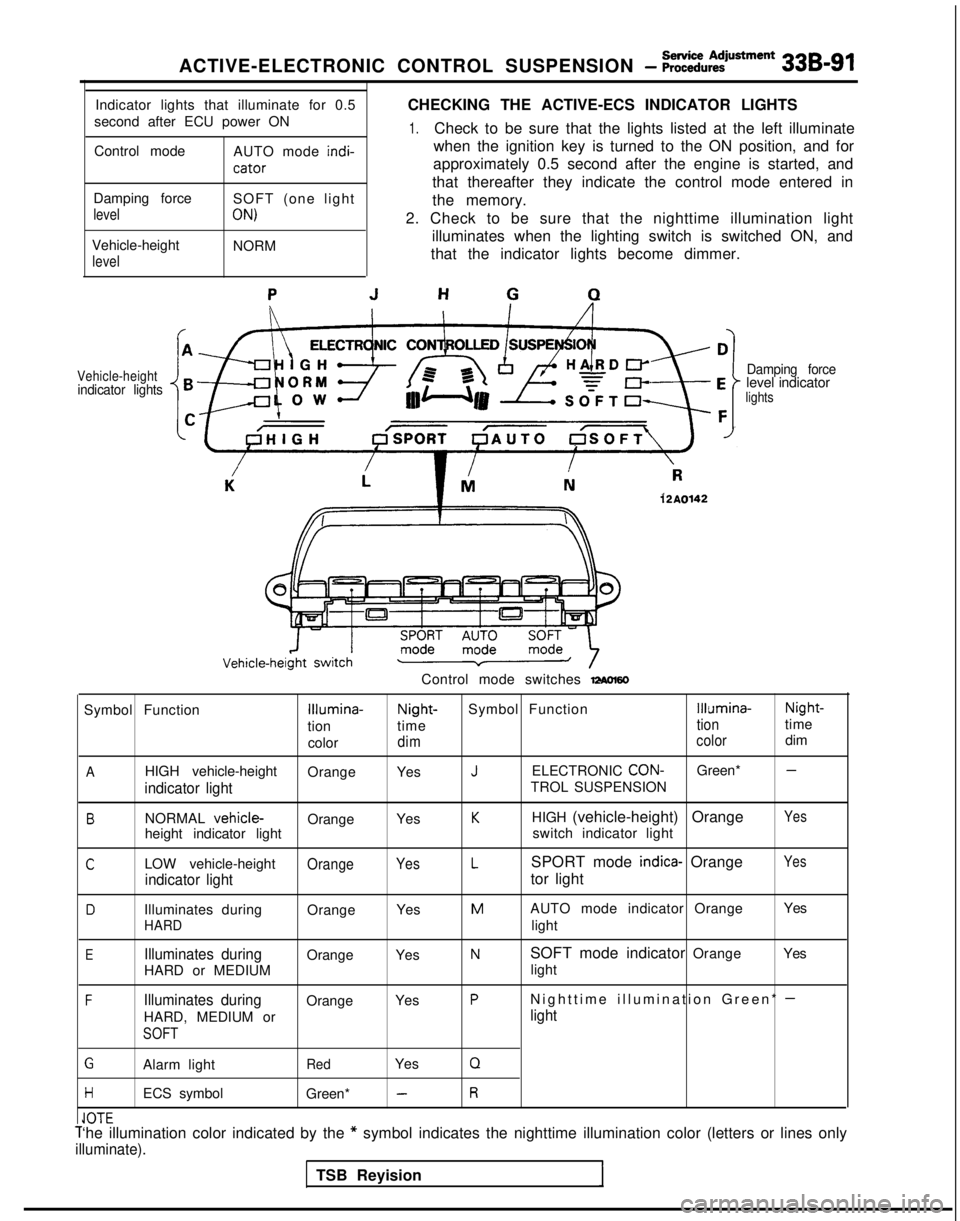
ACTIVE-ELECTRONIC CONTROL SUSPENSION - %ii%:justment 33B-91
Indicator lights that illuminate for 0.5
second after ECU power ON
Control mode AUTO mode indi-
cator
CHECKING THE ACTIVE-ECS INDICATOR LIGHTS
1.Check to be sure that the lights listed at the left illuminate
when the ignition key is turned to the ON position, and for
approximately 0.5 second after the engine is started, and
that thereafter they indicate the control mode entered in
Damping force
level
Vehicle-height
level
SOFT (one light
ON)
NORM the memory.
2. Check to be sure that the nighttime illumination light illuminates when the lighting switch is switched ON, and
that the indicator lights become dimmer.
Vehicle-heightindicator lights Damping forcelevel indicatorlights
12A0142
Control mode switches -60
Symbol FunctionIllumina-Night-
Symbol FunctionIllumina- Night-
tion time
tiontime
color
dim colordim
AHIGH vehicle-height
OrangeYesJELECTRONIC CON-Green* -
indicator lightTROL SUSPENSION
BNORMAL vehicle-OrangeYesKHIGH (vehicle-height) OrangeYes
height indicator light switch indicator light
CLOW vehicle-heightOrangeYesLSPORT mode indica- OrangeYes
indicator lighttor light
DIlluminates during
OrangeYesMAUTO mode indicator Orange Yes
HARDlight
EIlluminates duringOrange
YesNSOFT mode indicator Orange Yes
HARD or MEDIUM light
FIlluminates duringOrange
YesPNighttime illumination Green* -
HARD, MEDIUM orlight
SOFT
GAlarm lightRedYesQ
HECS symbol
Green* -R
IA-r-Cl”lCT‘he illumination color indicated by the * symbol indicates the nighttime illumination color (letters or lines on\
ly
illuminate).
TSB Reyision
Page 1262 of 1273
ALPHABETICAL INDEX1
A
ABS
Checking by the ABS Warnrng Light................
. 35-68-l
Troubleshooting ...........................
35-l 5-l
ABS POWER RELAY, Chec
k 35-74-l
ACCELERATOR CABLE
Inspection and Adjustment
13-398-l
Inspection and Adjustment
ACCELERATOR SWITCH, Inspection and Adjustment 13-329-I
A/C COMPRESSOR CLUTCH RELAY
On-vehicle Inspection
.............
. 13-285-l
On-vehrcle
Inspection
. 13-83-t
On-vehicle Inspection
. 13-176-l
ACTIVE-ECS ON-BOARD DIAGNOSTIC, Check......
. 338-88-I
ACTIVE-ECS RELAY.......................
. 338-141
-I
ACTIVE-ECS SENSOR....
.
...... ............ 338-138-I
ACTIVE-ECS SYSTEM
Checking by Using Alarm Light
.................
. 338-87-I
Operation Check ........................... 338-90-I
AERO PARTS..
.
........................... 51-18-l
AIR CLEANER...............................
. 15-9-I
AIR CLEANER ELEMENT
Inspection and Replacement
....................
. 15-6-l
Maintenance .......................... 00-39-l
AIR COMPRESSOR..........................
. 338-125-I
AIR CONDITIONING SWITCH
Emission control
...........................
.
17-21 -I
Heater, Air
Conditionrng
and Ventilation .............. 55-29-l
On-vehicle Inspection
On-vehicle Inspection
. 13-83-l
On-vehicle Inspection
. 13-176-l
AIR TUBE..............
.
....................... 338-133-I
ALARM LIGHT, Check. ......................... 338-87-I
ALARM SYSTEM, Theft ..........................
54-165-11
ALIGNMENT
Front Wheel, Adjustment .......................
. 33A-5-l
Rear
Wheel, inspection
. 34-23-l
Rear Wheel, Inspection
. 34-5-l
ANTENNA ......................................
54-153-11
ANTI-LOCK BRAKING SYSTEM, Troubleshooting .........
.
35-15-1
ARM
Lower
. 338-103-I
Lower
.
33A-10-I
Lower
................... 34-28-l
Torsion
.
338-l 19-l
Torsion
...................34-l 5-lTrailing
................. 34-31-l
Upper
.................. 34-28-l
AUDIO
SYSTEM................
.
.................
54-l 12-11
AUTO-CRUISE CONTROL. ..........................
. 13-408-I
AUTO-CRUISE CONTROL INDIVIDUAL PARTS, inspection..
. 13-401-I
AUTO-CRUISE CONTROL SYSTEM...................
. 13-332-l
AUTO-CRUISE CONTROL SYSTEM, Inspection..........
. 13-397-l
AUTOMATIC TRANSAXLE, Maintenance ................. 00-43-I
AXLE
Rear, Maintenance
...............................
. 00-45-I
Torsion
.
338-l 19-l
Torsion
.
......................... 34-15-l
AXLE HUB
Rear
Rear CFWD-Rear
Drum Brakes> ................... 27-6-l
AXLE SHAFT
.
27-17-1
B
BACKLASH. Total, Rear Axle, Check
. 27-15-l
BALL JOINT
Rotation Starting Torque Check ...................... 378-8-I
Tie Rod End, Staning Torque Check .................. 37A-15-l
Tie Rod End, Variation Check ....................... 37A-15-l
BALL JOINT SEALS, Maintenance ..................... 00-45-I
BAR
Stabilizer
. 338-106-I
Stabilizer
. 33A-13-l
Stabilizer
. 34-37-l
BAROMETRIC PRESSURE SENSOR
On-vehicle Inspection
................
. 13-266-l
On-vehicle Inspection
On-vehicle Inspection
. 13-154-l
BASIC IDLE SPEED
Adjustment
...........................
. 13-245-l
Adjustment
Adjustment
. 13-133-l
BATTERY.........................................
.
54-2-11
BATTERY, Flat Remedy.
.............................
. 35-75-l
BEARING
Wheel, Adjustment
. 338-87-I
Wheel, Adjustment
BELT
Drive, Compressor, Adjustment
....................
. 55-17-l
Drive (For Water Pump and Generator), Maintenance ..... 00-41-I
Drive, Tension Adjustment
Drive, Tension Adjustment
Seat..........................................
. 52-39-l
Timing
Timing
. 11-34-l
Timing, Maintenance ............................... 00-40-I
Timing, Tension Adjustment
BLEEDING
Clutch
..........................................
. 21-6-l
4ws...........................................
. 370-4-I
Service Brakes. .................................. 35-57-l
Steering ........................................ 37A-22-l
BLOWER..........................................
. 55-32-l
BOOSTER
Brake
.........................................
. 35-85-l
Brake, Operating Inspection ......................... 35-54-l
BOOST METER, On-vehicle Inspection
BOOTS, Drive Shaft, Maintenance ....................... 00-45-I
BRAKE
Disc, Front
......................................
. 35-94-l
Disc, Rear.....................................
.
35-l 14-l
BRAKE BOOSTER
...................................
. 35-85-l
BRAKE BOOSTER, Operating Inspection .................. 35-54-l
BRAKE DISC
Front, Run-out Check.
.............................
. 35-63-l
Front, Run-out Correction ........................... 35-64-l
Front, Thickness Check ............................. 35-65-l
Rear, Run-out Check ............................... 35-66-l
Rear, Run-out Correction. ........................... 35-66-l
Rear, Thickness Check............................
. 35-66-l
BRAKE DRUM, tnside
Diameter, Check ................... 35-67-l
BRAKE FLUID LEVEL SENSOR, Check...................
. 35-54-l
BRAKE FLUID PRESSURE SWITCH
AWD-ABS (Up to 1991 Models)
....................
.
35-133-l
AWD-ABS
(Up to 1991 models), Check ...............
. 35-75-l
BRAKE HOSES, Maintenance ........................... 06-45-t
BRAKELINE
........................................
35-87-l
Page 1266 of 1273
ALPHABETICAL INDEX5
Fuel, Maintenance.
.
Power Steering
Transaxle
011 Cooler
Vacuum
..,...,..,.......
Water
Water
Water
HUB
End Play inspection
End Play, Inspection
Front Axl
e
Rear Axle
Rear Axle
HYDRAULIC UNIT
HYDRAULIC UNIT, Inspection
I 00-39-I
37A-58-I
23-l
00-l
17-4-I
14-26-I
14-28-l
14-23-l
338-86-I
26-5-l
26-l-l
27-8-l
27-6-1
35-121-l
35-70-t
IAC VALVE POSITION SENSOR, On-vehicle Inspection
.
13-162-l
IDLE AIR CONTROL MOTOR
DC Motor,
On-vehicle
Inspection
13-184-I
Stepper Motor, On-vehicle Inspection
IDLE SPEED
Basic, Adjustment
.....................
.
13-245-l
Basic, Adjustment
.
13-33-l
Basrc. Adjustment
.
13-133-l
Curb, Inspection
...... 13-245-I
Curb, Inspection
.
...
...........
.
13-32-I
Curb, Inspection
.
13-133-I
IDLE SPEED CONTROL MOTOR (DC Motor),
On-vehrcle Inspectron
.
13-93-l
IDLE SPEED CONTROL MOTOR POSITION SENSOR,On-vehicle Inspection
.
13-64-I
IDLE-UP OPERATION, Check ....................... 55-24-l
IGNITION COIL
On-vehtcle
Inspection
On-vehicle
Inspectron
.
13-96-l
On-vehicle
Inspection
.
13-186-I
IGNITION POWER TRANSISTOR
On-vehrcle
Inspection
On-vehicle Inspection
On-vehicle
inspection
.
13-186-l
IGNITION SWITCH
Chassis Electrical.
...........................
.
.....
54-6-11
On-vehicle Inspection
.
13-284-l
On-vehicle Inspection
... 13-78-l
On-vehicle Inspection
On-vehicle Inspection
On-vehicle inspection
.
13-171 -IIGNITION SYSTEM...........................
.
16-32-11.....
.
IGNITION TIMING Adjustment
16-40-11
Adjustment
.
....................
INDICATOR...........................
.
.......... 33B-140-l
INDIVIDUAL PARTS, Auto-cruise Control, Inspection .......
13-401 -I
INFLATION PRESSURE, Tire, Check......................
.
31-4-l
INJECTORS
On-vehicle Inspection
..................
.
13-295-I
On-vehicle Inspection
.
13-90-I
On-vehicle Inspection
........... 13-l
81-l
INSTRUMENT PANEL ................................. 52-22-l
INTAKE AIR TEMPERATURE SENSOR
Emission Control
..............................
.
17-21 -I
On-vehicle inspection
.................
.
13-263-l
On-vehicle Inspection
.
13-51-IOn-vehicle Inspection
INTAKE CHARGE PRESSURE CONTROL SYSTEM,Inspection . . . . . . . . . . . . . . .
INTAKE MANIFOLD
DOHC
,.. . . . . . . . . . . ,,... SOHC-WALVE
SOHC-l
GVALVE
K
KEY INTERLOCK MECHANISM, Check
.
KICKDOWN SERVO, Adjustment
KNOCK SENSOR, On-vehicle Inspection
KNUCKL
E
L
LASH ADJUSTERS
Check
>
Check
LATCHDoor, Fron
t
Door, Rear
LATERAL ROD
Active-EC
S
Rear Suspesion
LEAK, Refrrgerant. Repair Procedure
LEVELFluid, Transaxle, Inspection
Oil, Transfer, Inspection.
LEVERParking Brak
e
Parking Brake, Stroke Check
Selector, Operation Check.
Shift
Shift
LIDTrunk ._, . . . . . . . . . . . . .
Trunk, Adjustmen
t
LIGHT
......
......
......
.....
......
......
.....
......
......
......
......
......
......
......
......
......
......
......
......
......
.......
........
.......
........
........
........
........
........
........
........
........
........
........
........
........
........
........
Alarm, Chec
k
Rear Combination
Stop, High Mounted
LIGHTING SYSTEM
LINEBrake
Fuel
Fuel
Fuel
Fuel
Refrigerant
.
Vapor
Vapor
Vapor
Vapor
LINE PRESSURE, Adjustment
LININGBrake, Thickness Check.
Rear Drum Brake, Maintenance
LOOSE PANE
L
LOWER ARMActive-KS
Front Suspensio
n
Rear Suspesion
........
...............
.......
........
........
........
........
........
........
........
........
.........
.........
.........
.........
.........
........ 13-152-I
15-7-l
15-21 -I
15-14-I
15-18-I
23-83-1
23-86-i
13-287-l
26-6-l
11-57-1
1 l-7-l
42-96-l
42-99-l
338-l 17-l
34-14-I
’
55-21-I
23-82-l
23-82-l
36-4-l
36-2-l
23-83-l
22-19-l
22-9-l
42-57-l
42-50-I
338-87-I
54-95-11
54-96-11
54-38-11
35-87-I
13-326-I
13-324-I
13-113-I
13-I
95-l
55-54-l
13-326-I
13-324-l
13-I 13-l
13-195-1
23-88-l
35-67-l
00-44-I
42-62-i
338-l
03-l
33A-10-I
34-28-l