1989 MITSUBISHI GALANT alarm
[x] Cancel search: alarmPage 988 of 1273
ACTIVE-ELECTRONIC CONTROL SUSPENSION - Troubleshooting 33B-49
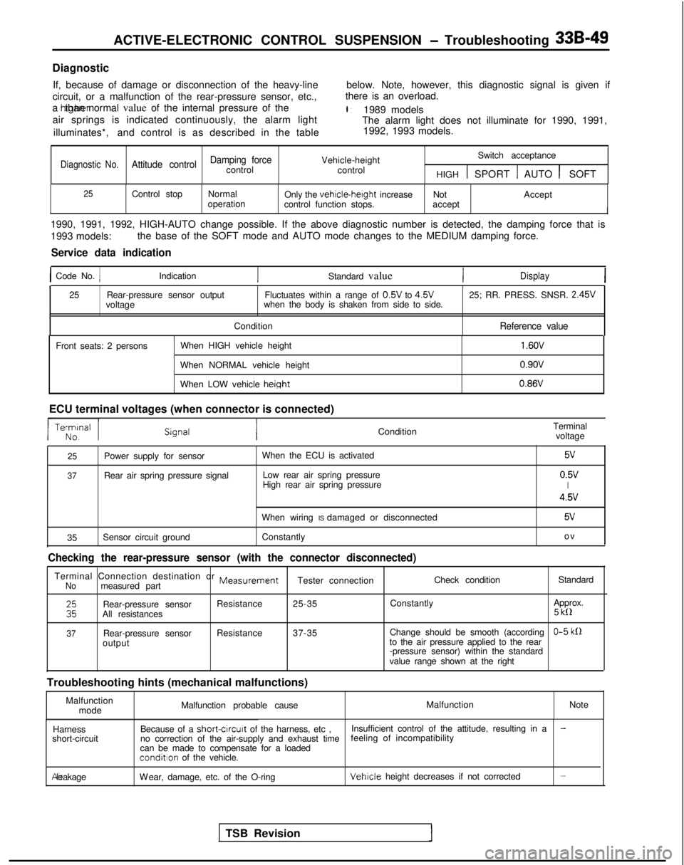
Diagnostic
If, because of damage or disconnection of the heavy-line below. Note, however, this diagnostic signal is given if
circuit, or a malfunction of the rear-pressure sensor, etc., there is an overload.
a htgher than normal value of the internal pressure of the
l :1989 models
air springs is indicated continuously, the alarm light The alarm light does not illuminate for 1990, 1991,
illuminates*, and control is as described in the table 1992, 1993 models.
I1
Damping forceVehicle-heightSwitch acceptanceDiagnostic No.Attitude controlcontrol
control
HIGH 1 SPORT 1 AUTO 1 SOFT
25Control stopNormal
Only the vehicle-height
increase Not Accept
operation control function stops. accept
I
1990, 1991, 1992, HIGH-AUTO change possible. If the above diagnostic num\
ber is detected, the damping force that is
1993 models:the base of the SOFT mode and AUTO mode changes to the MEDIUM damping fo\
rce.
Service data indication
1 Code No. 1Indication
Standard valueDisplay
25Rear-pressure sensor output Fluctuates within a range of 0.5V
to 4.5V
25; RR. PRESS. SNSR. 2.45V
voltage when the body is shaken from side to side.
Condition
Reference value
Front seats: 2 persons When HIGH vehicle height
When NORMAL vehicle height
When LOW vehicle
height
1.6OV
0.9ov 0.86V
ECU terminal voltages (when connector is connected) ConditionTerminal
voltage
25Power supply for sensor
37Rear air spring pressure signal When the ECU is activated
Low rear air spring pressure
High rear air spring pressure
5v
0.5vI
4.5v
When wiring IS damaged or disconnected5v
35 Sensor circuit ground
Constantly o
v
Checking the rear-pressure sensor (with the connector disconnected)
Terminal Connection destination or MeasurementNomeasured part
Tester connection
Check condition
Standard
ERear-pressure sensorResistance
25-35 Constantly Approx.
All resistances 5 kll
37Rear-pressure sensor
Resistance
37-35 Change should be smooth (accordingO-5 klloutput to the air pressure applied to the rear
-pressure sensor) within the standard
value range shown at the right
Troubleshooting hints (mechanical malfunctions) Malfunctionmode Malfunction probable cause
Malfunction
Note
Harness
short-circuit Because of a short-circurt
of the harness, etc , Insufficient control of the attitude, resulting in a
-no correction of the air-supply and exhaust time feeling of incompatibility
can be made to compensate for a loaded
condition of the vehicle. Air leakage
Wear, damage, etc. of the O-ring
Vehicle height decreases if not corrected-
TSB Revision
Page 994 of 1273
ACTIVE-ELECTRONIC CONTROL SUSPENSION - Troubleshooting 33B-55
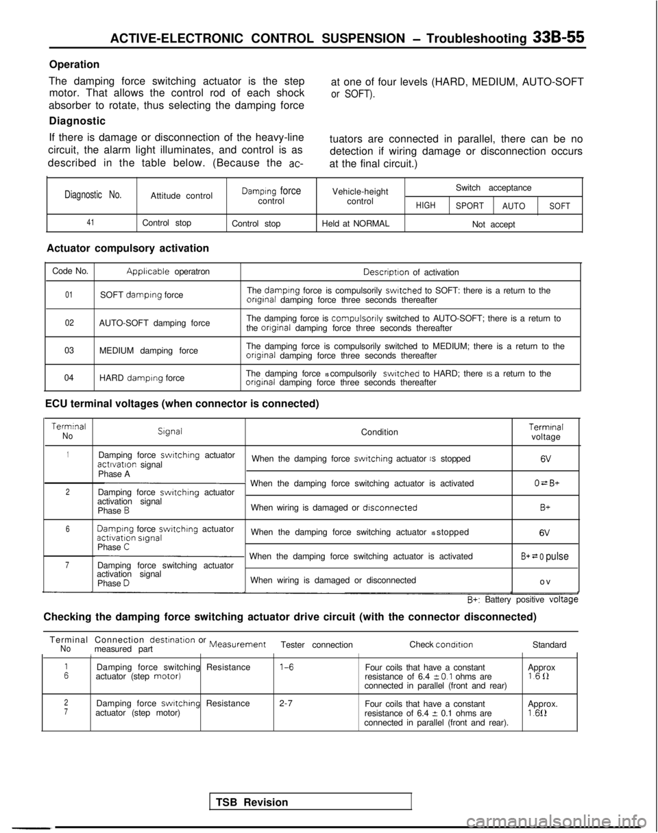
Operation
The damping force switching actuator is the step motor. That allows the control rod of each shock at one of four levels (HARD, MEDIUM, AUTO-SOFT
or SOFT).
absorber to rotate, thus selecting the damping force
Diagnostic
If there is damage or disconnection of the heavy-line
circuit, the alarm light illuminates, and control is as
described in the table below. (Because the
ac-
tuators are connected in parallel, there can be no detection if wiring damage or disconnection occurs
at the final circuit.)
Diagnostic No.Attitude control
41Control stop
Actuator compulsory activation
Damplng forcecontrol
Control stop Vehicle-height
control
Held at NORMALHIGH
Switch acceptance
SPORT AUTO
Not accept
SOFT
Code No.Applrcable operatron Descriptron
of activation
01SOFT damplng force The damplng force is compulsorily swltched to SOFT: there is a return to theonginal damping force three seconds thereafter
02AUTO-SOFT damping force The damping force is compulsorily switched to AUTO-SOFT; there is a return to
the onginal damping force three seconds thereafter
03 MEDIUM damping force The damping force is compulsorily switched to MEDIUM; there is a return \
to the
onginal damping force three seconds thereafter
04 HARD
damplng force The damping force IS compulsorily switched to HARD; there IS a return to theonginal damping force three seconds thereafter
ECU terminal voltages (when connector is connected) Terminal
No
Slgnal
Condition Terminal
voltage
1Damping force swrtchlng
actuatoractlvatlon signal When the damping force switching actuator IS stopped6V
Phase AO=B+2p When the damping force switching actuator is activated
Damping force switching actuator
activation signal
Phase
BWhen wiring is damaged or dlsconnectedB+
6 Damplng
force switchrng
actuatoractivation slgnal
When the damping force switching actuator IS stopped 6V
Phase C
7p When the damping force switching actuator is activated
Damping force switching actuatorB+ = 0 pulse
activation signal
Phase DWhen wiring is damaged or disconnected o
v
B+: Battery positive voltage
Checking the damping force switching actuator drive circuit (with the c\
onnector disconnected)
TSB Revision
Terminal Connection
destination or MeasurementNomeasured part
Tester connection
Check condltlonStandard1
ADamping force switching Resistance 1-6
Four coils that have a constant
actuator (step motor)Approx
resistance of 6.4 i-O.1 ohms are 1611
connected in parallel (front and rear)
2Damping force swltchlng Resistance 2-7
Four coils that have a constant7actuator (step motor) Approx.
resistance of 6.4 t 0.1 ohms are1.612connected in parallel (front and rear).
Page 996 of 1273
ACTIVE-ELECTRONIC CONTROL SUSPENSION - Troubleshooting 33B-57
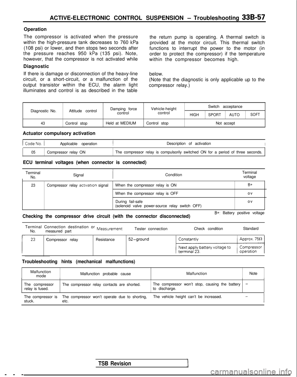
Operation
The compressor is activated when the pressure
within the high-pressure tank decreases to 760
kPa
(108 psi) or lower, and then stops two seconds after
the pressure reaches 950
kPa (135 psi). Note,
however, that the compressor is not activated while
Diagnostic If there is damage or disconnection of the heavy-line
circuit, or a short-circuit, or a malfunction of the
output transistor within the ECU, the alarm light illuminates and control is as described in the table the return pump is operating. A thermal switch is
provided at the motor circuit. This thermal switch
functions to interrupt the power to the motor (in
order to protect the compressor) if the temperature
within the compressor becomes high.
below.
(Note that the diagnostic is only applicable up to the
compressor relay.)
Diagnostic No.
43
Attitude control
Control stop Damping force
control
Held at MEDIUM Vehicle-height
control
Control stopHIGH
Switch acceptance
SPORT AUTOSOFT
Not accept
Actuator compulsory activation
1 CodeNo. /Applicable operationIDescription of activationI
05Compressor relay ON The compressor relay is compulsorily switched ON for a period of three s\
econds.
ECU terminal voltages (when connector is connected)
TerminalNo.Signal ConditionTerminal
voltage
23Compressor relay actrvatron
signal When the compressor relay is ONB+
When the compressor relay is OFF o
v
During fail-safe ov
(solenoid valve power-source relay switch OFF) ---
TSB Revision
Checking the compressor drive circuit (with the connector disconnected)\
B+: Battery positive voltage
Terminal Connection destination or
MeasurementNo.measured part Tester connection
Check conditionStandard
~~
Compressor relay Resistance52-ground
Troubleshooting hints (mechanical malfunctions)
Malfunction
mode Malfunction probable cause
Malfunction
Note
The compressor relay is fused. The compressor relay contacts are shorted.
The compressor won’t stop, causing the battery
-to discharge.
The compressor is The compressor won’t operate due to shorting, The vehicle height can’t be increased.
-
stuck.
etc.
Page 998 of 1273
ACTIVE-ELECTRONIC CONTROL SUSPENSION - Troubleshooting 33B-59
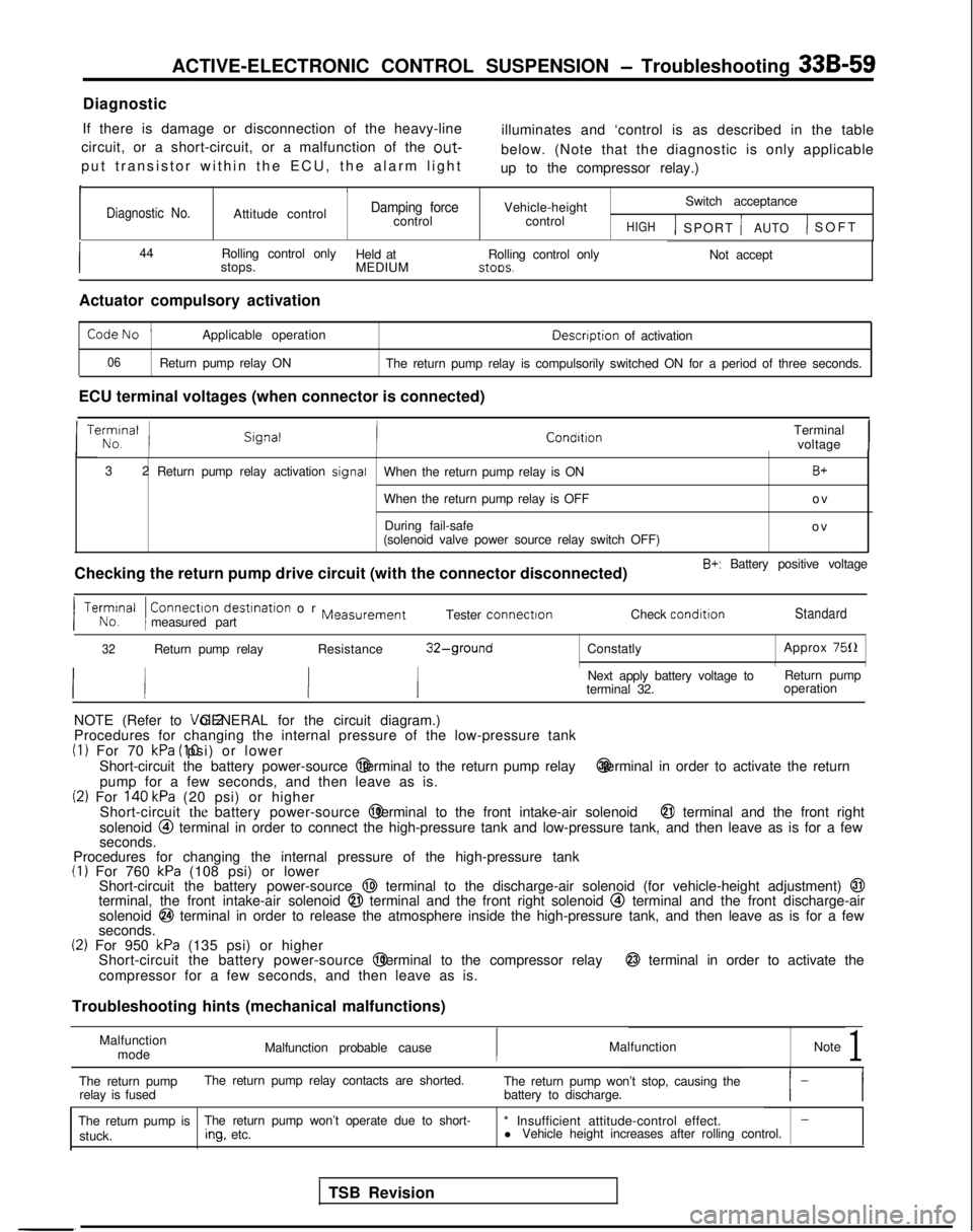
Diagnostic
If there is damage or disconnection of the heavy-line illuminates and ‘control is as described in the table
circuit, or a short-circuit, or a malfunction of the
out-
put transistor within the ECU, the alarm ligh
t
below. (Note that the diagnostic is only applicable
up to the compressor relay.)
II/6
Diagnostic No.Attitude controlDamping forcecontrol Vehicle-height
control Switch acceptanceHIGH1 SPORT jAUTO) SOF
T
I44
Rolling control only
Held at
stops. MEDIUMRolling control only stoos.
Not accept
Actuator compulsory activation
CodeNo ’Applicable operation Descnption
of activation
06Return pump relay ON
The return pump relay is compulsorily switched ON for a period of three \
seconds.
ECU terminal voltages (when connector is connected) Terminalvoltage
I
3
2
Return pump relay activation signal
When the return pump relay is ON
B+
When the return pump relay is OFF o
v
During fail-safe ov
(solenoid valve power source relay switch OFF)
Checking the return pump drive circuit (with the connector disconnected\
)
B+: Battery positive voltage Connectron
destrnation or Measurementmeasured part Tester connectron
Check condrtronStandard
32Return pump relay
Resistance32-groundConstatly Approx 750INext apply battery voltage to
terminal 32. Return pump
operation
NOTE (Refer to Vol.2 GENERAL for the circuit diagram.)
Procedures for changing the internal pressure of the low-pressure tank
(1) For 70 kPa (IO psi) or lower
Short-circuit the battery power-source @ terminal to the return pump relay @ terminal in order to activate the return
pump for a few seconds, and then leave as is.
(2) For 140 kPa (20 psi) or higher
Short-circuit the battery power-source @ terminal to the front intake-air solenoid @I terminal and the front right
solenoid @I terminal in order to connect the high-pressure tank and low-pressure ta\
nk, and then leave as is for a few
seconds.
Procedures for changing the internal pressure of the high-pressure tank
(I) For 760 kPa (108 psi) or lower
Short-circuit the battery power-source @I terminal to the discharge-air solenoid (for vehicle-height adjustment)\
@Iterminal, the front intake-air solenoid @I terminal and the front right solenoid @ terminal and the front discharge-air
solenoid @I terminal in order to release the atmosphere inside the high-pressure ta\
nk, and then leave as is for a few
seconds.
(2) For 950 kPa (135 psi) or higher
Short-circuit the battery power-source @ terminal to the compressor relay @ terminal in order to activate the
compressor for a few seconds, and then leave as is.
Troubleshooting hints (mechanical malfunctions)
Malfunctionmode Malfunction probable cause
Malfunction
Note
1
The return pumpThe return pump relay contacts are shorted.
relay is fused The return pump won’t stop, causing the
battery to discharge.
The return pump is The return pump won’t operate due to short-
* Insufficient attitude-control effect.
-
stuck.ing.
etc. l
Vehicle height increases after rolling control.
TSB Revision
Page 1000 of 1273
ACTIVE-ELECTRONIC CONTROL SUSPENSION - Troubleshooting 33B-61
Operation
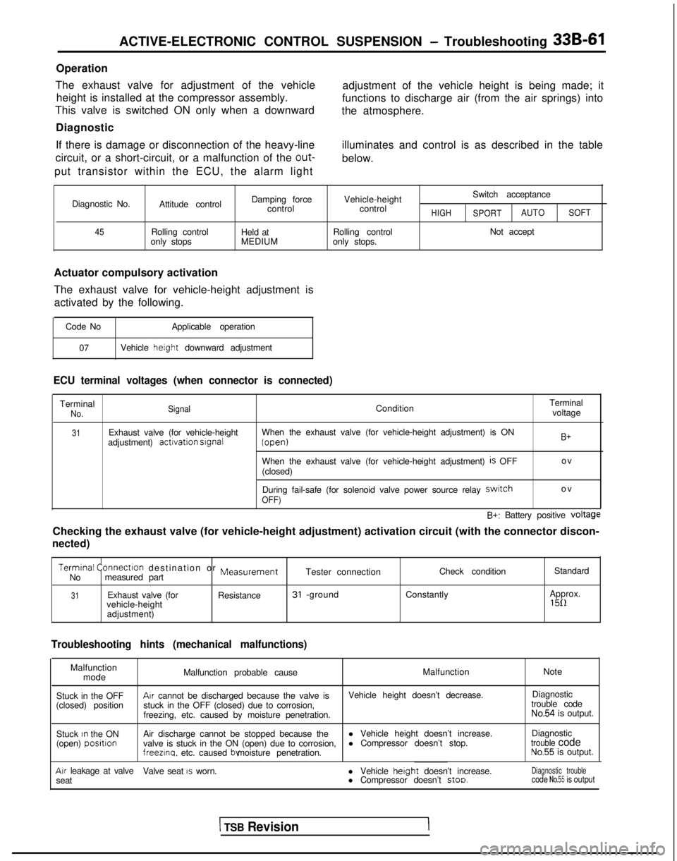
The exhaust valve for adjustment of the vehicle height is installed at the compressor assembly.
This valve is switched ON only when a downward
Diagnostic
If there is damage or disconnection of the heavy-line
circuit, or a short-circuit, or a malfunction of the out-
put transistor within the ECU, the alarm light adjustment of the vehicle height is being made; it
functions to discharge air (from the air springs) into
the atmosphere.
illuminates and control is as described in the table
below.
Diagnostic No.
45
Attitude control
Rolling control
only stops Damping force
control
Held at
MEDIUM Vehicle-height
control
Rolling control
only stops. Switch acceptanceHIGHSPORT
AUTO
SOFT
Not accept
Actuator compulsory activation
The exhaust valve for vehicle-height adjustment is activated by the following.
Code No Applicable operation
07 Vehicle height
downward adjustment
ECU terminal voltages (when connector is connected)
TerminalNo. SignalCondition Terminal
voltage
31Exhaust valve (for vehicle-height
adjustment) activation srgnalWhen the exhaust valve (for vehicle-height adjustment) is ON (open)
When the exhaust valve (for vehicle-height adjustment)
is OFF
(closed)
B+
o
v
During fail-safe (for solenoid valve power source relay
swatcho
v
OFF)
B+: Battery positive voltage
Checking the exhaust valve (for vehicle-height adjustment) activation \
circuit (with the connector discon-
nected)
Termtnal
Connectlon destination or MeasurementCheck condition Standard
No measured part Tester connection
31Exhaust valve (for
Resistance31 -groundConstantly Approx.
vehicle-height1511adjustment)
Troubleshooting hints (mechanical malfunctions)
Malfunction mode Malfunction probable cause
Malfunction
Note
Stuck in the OFF
Arr cannot be discharged because the valve is Vehicle height doesn’t decrease.Diagnostic
(closed) position stuck in the OFF (closed) due to corrosion, trouble code
freezing, etc. caused by moisture penetration.
No.54 is output.
Stuck
rn the ON
(open) positlonAir discharge cannot be stopped because the l Vehicle height doesn’t increase.Diagnostic
valve is stuck in the ON (open) due to corrosion, l Compressor doesn’t stop.trouble codefreezlna.
etc. caused bv moisture penetration.No.55 is output.
Arr leakage at valve
Valve seat IS worn.
seat l Vehicle herght
doesn’t increase.
l Compressor doesn’t stoo.Diagnostic troublecode No.55 is output
1 TSB Revision
Page 1002 of 1273
ACTIVE-ELECTRONIC CONTROL SUSPENSION - Troubleshooting 3%~63
Operation
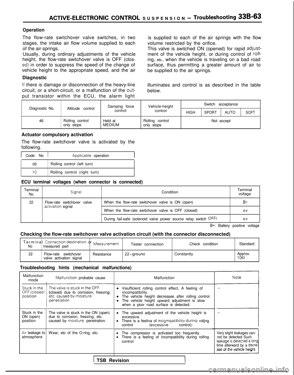
The flow-rate switchover valve switches, in twostages, the intake air flow volume supplied to each
of the air springs.
Usually, during ordinary adjustments of the vehicle
height, the flow-rate switchover valve is OFF (clos-
ed) in order to suppress the speed of the change of
vehicle height to the appropriate speed, and the air
Diagnostic is supplied to each of the air springs with the flow
volume restricted by the orifice.
This valve is switched ON (opened) for rapid
adjust-
ment of the vehicle height, or during control of roll-
ing, etc., when the vehicle is traveling on a bad road
surface, thus permitting a greater amount of air to
be supplied to the air springs.
If there is damage or disconnection of the heavy-line illuminates and control is as described in the table
circuit, or a short-circuit, or a malfunction of the out-
below.
put transistor within the ECU, the alarm light
Switch acceptance
Diagnostic No. Attitude control Damping force
Vehicle-height
control control
HIGHSPORT AUTOSOFT
46 Rolling control
Held at Rolling control
Not accept
only stops MEDIUM
only stops
Actuator compulsory activation
The flow-rate switchover valve is activated by the
following.
1 Code No 1 Applrcable
operation
09Rolling control (left turn)
10Rolling control (right turn)
ECU terminal voltages (when connector is connected)
TerminalNo.SrgnalCondition Terminal
voltage
22Flow-rate switchover valve actrvation
signal When the flow-rate switchover valve is ON (open)B+
When the flow-rate switchover valve is OFF (closed)
o
v
During fail-safe (solenoid valve power source relay switch
OFF)o
v
B+: Battery positive voltage
Checking the flow-rate switchover valve activation circuit (with the co\
nnector disconnected) Terminal Connectron
destinatron
or
MeasurementNomeasured part Tester connection
Check condition
Standard
22Flow-rate switchover
Resistance22-groundConstantly Approx.
valve activation signal1 OIL
Troubleshooting hints (mechanical malfunctions)
Malfunction mode Malfunctron
probable cause
(closed) due to corrosion, freezing
Stuck in the The valve is stuck in the ON (open)
ON (open) due to corrosion, freezing, etc.
position caused by morsture
penetration.
Arr leakage to
W
ear, etc of the O-ring, etc.
atmosphere Malfunction
l Insufficient rolling control effect, A feeling of
incompatibility.
l The vehicle height decreases after rolling control.
l The vehicle height upward adjustment is slow
when a poor road surface is detected.
lThe upward adjustment of the vehicle height is
excessive.
lThere is a feelina of incomoatibilitv durinq rolling
control (excessi;e control): - -
lThe compressor is activated too frequently.lThere is a feeling of incompatibility during rolling
control
“i
4
-
Very slight leakages can-not be detected Such
time afterward by a
decre
ase of the vehicle height
\ TSB Revision
Page 1004 of 1273
ACTIVE-ELECTRONIC CONTROL SUSPENSION - Troubleshooting 33B-65
Operation
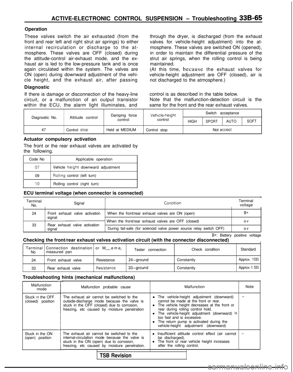
These valves switch the air exhausted (from the
front and rear left and right strut air springs) to either internal recirculation or discharge to the at-
mosphere. These valves are OFF (closed) during
the attitude-control air-exhaust mode, and the ex- haust air is led to the low-pressure tank and is once
again circulated within the system. The valves are
ON (open) during downward adjustment of the vehi-
cle height, and the exhaust air, after passing
Diagnostic through the dryer, is discharged (from the exhaust
valves for vehicle-height adjustment) into the at-
mosphere. These valves are switched ON (opened),
in order to maintain the differential pressure of the
strut air springs, when the rolling control is being maintained.
(At this time, because the exhaust valves for
vehicle-height adjustment are OFF (closed), air is not discharged to the atmosphere.)
If there is damage or disconnection of the heavy-line control is as described in the table below.
circuit, or a malfunction of an output transistor Note that the malfunction-detection circuit is the
within the ECU, the alarm light illuminates, and same for the front and the rear exhaust valves.
Damping force Vehrcle-height
Switch acceptance
Diagnostic No. Attitude control
controlcontrol
HIGHSPORTAUTOSOFT
47
Control stooHeld at MEDIUM Control stop Not acceot
Actuator compulsory activation
The front or the rear exhaust valves are activated by
the following.
Code No Applicable operation
07Vehicle height downward adjustment
09 Rollrng
control (left turn)
10Rolling control (right turn)
ECU terminal voltage (when connector is connected) Terminal No. Signal Terminal
voltage
24
33 Front exhaust valve activation
When the front/rear exhaust valves are ON (open)
B+signal~ When the front/rear exhaust valves are OFF (closed) o
v
Rear exhaust valve activation
signal During fail-safe (for solenoid valve power source relay switch OFF)
ov
B+: Battery positive voltage
Checking the front/rear exhaust valves activation circuit (with the con\
nector disconnected)
II ITerminal Connection destination or M
easurem
e
nt
No measured pan Tester connection
Check condition
Standard
I
24Front exhaust valve Resistance24-ground
33Rear exhaust valve Resistance33-ground
Troubleshooting hints (mechanical malfunctions)
Constantly
Constantly
Approx. 100
Approx 1
OQ
Malfunction mode
Stuck
In the OFF
(closed) position
Stuck in the ON
(open) position
I
Malfunction probable cause Malfunction
Note
The exhaust air cannot be switched to the outside-discharge mode because the valve is
stuck in the OFF (closed) due to corrosion,
freezing, etc caused by moisture penetration l The vehicle-height adjustment (downward)
-cannot be made at the front or rear.
l The vehicle height decreases at the front or
rear during rolling control hold.
l The vehicle-height adjustment (downward)
istoo fast and is excessive.
l The return pump is activated during the
vehicle-height adjustment (downward)
The exhaust air cannot be switched to the l Insufficient attitude control effect (air cannot
-internal-circulation mode because the valve is
be discharged).
stuck in the ON (open) due to corrosion, l
The front or rear vehicle height increases
freezing, etc caused by moisture penetration. after the rolling control.
TSB Revision
Page 1006 of 1273
ACTIVE-ELECTRONIC CONTROL SUSPENSION - Troubleshooting 33B-67
Operation
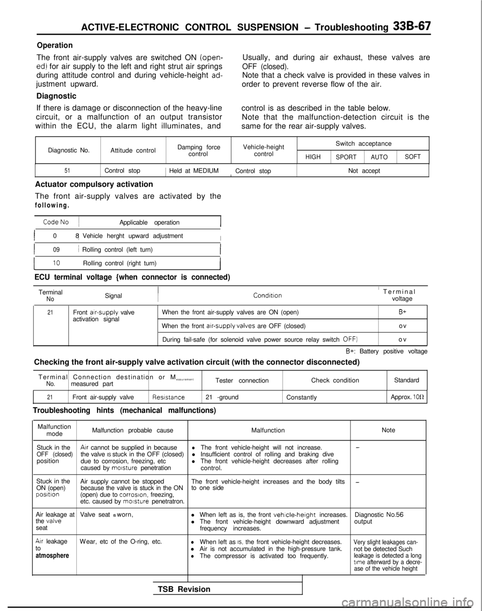
The front air-supply valves are switched ON (open-
ed) for air supply to the left and right strut air springs
during attitude control and during vehicle-height
ad-
justment upward.
Diagnostic
If there is damage or disconnection of the heavy-line
circuit, or a malfunction of an output transistor
within the ECU, the alarm light illuminates, and Usually, and during air exhaust, these valves are
OFF (closed).
Note that a check valve is provided in these valves in
order to prevent reverse flow of the air.
control is as described in the table below. Note that the malfunction-detection circuit is the
same for the rear air-supply valves.
Diagnostic No. Attitude control Damping force
control Vehicle-height
control
HIGH
Switch acceptance
SPORT AUTOSOFT
51Control stop1 Held at MEDIUM
Control stop Not acceptI
Actuator compulsory activation
The front air-supply valves are activated by the
following
.
CodeNo
~
Applicable operation
I0
8 1
Vehicle herght upward adjustment
I
I09i Rolling control (left turn)I
L10Rolling control (right turn)I
ECU terminal voltage {when connector is connected)
TerminalNoSignal Conditron’ Termina
l
voltage
21Front atr-supply
valve
activation signal When the front air-supply valves are ON (open)B+
When the front arr-supply valves
are OFF (closed) ov
During fail-safe (for solenoid valve power source relay switch
OFF]o
v
B+: Battery positive voltage
Checking the front air-supply valve activation circuit (with the connec\
tor disconnected)
Terminal Connection destination or M easurement
No.measured part Tester connection
Check conditionStandard
21Front air-supply valve Resrstance
21 -ground
Constantly Approx. 1011
Troubleshooting hints (mechanical malfunctions)
Malfunction
mode Malfunction probable cause
MalfunctionNote
l Insufficient control of rolling and braking dive
position due to corrosion, freezing, etc lThe front vehicle-height decreases after rolling
caused by morsture
penetration
control.
Stuck in the Air supply cannot be stopped
ON (open) The front vehicle-height increases and the body tilts
-because the valve is stuck in the ON
to one sideposrtion
(open) due to corrosron.
freezing,
etc. caused by morsture
penetratron.
Air leakage at Valve seat IS worn,
l When left as is, the front
vehrcle-height increases.Diagnostic No.56
the valvel The front vehicle-height downward adjustment output
seat frequency increases.
Arr leakageW
ear, etc of the O-ring, etc.
lWhen left as IS. the front vehicle-height decreases.Very slight leakages can-to
l not be detected Such
atmosphere Air is not accumulated in the high-pressure tank.lThe compressor is activated too frequently.leakage is detected a longtime
afterward by a decre-
ase of the vehicle height
TSB Revision