1989 MITSUBISHI GALANT alarm
[x] Cancel search: alarmPage 964 of 1273
ACTIVE-ELECTRONIC CONTROL SUSPENSION - Troubleshooting 33B-25
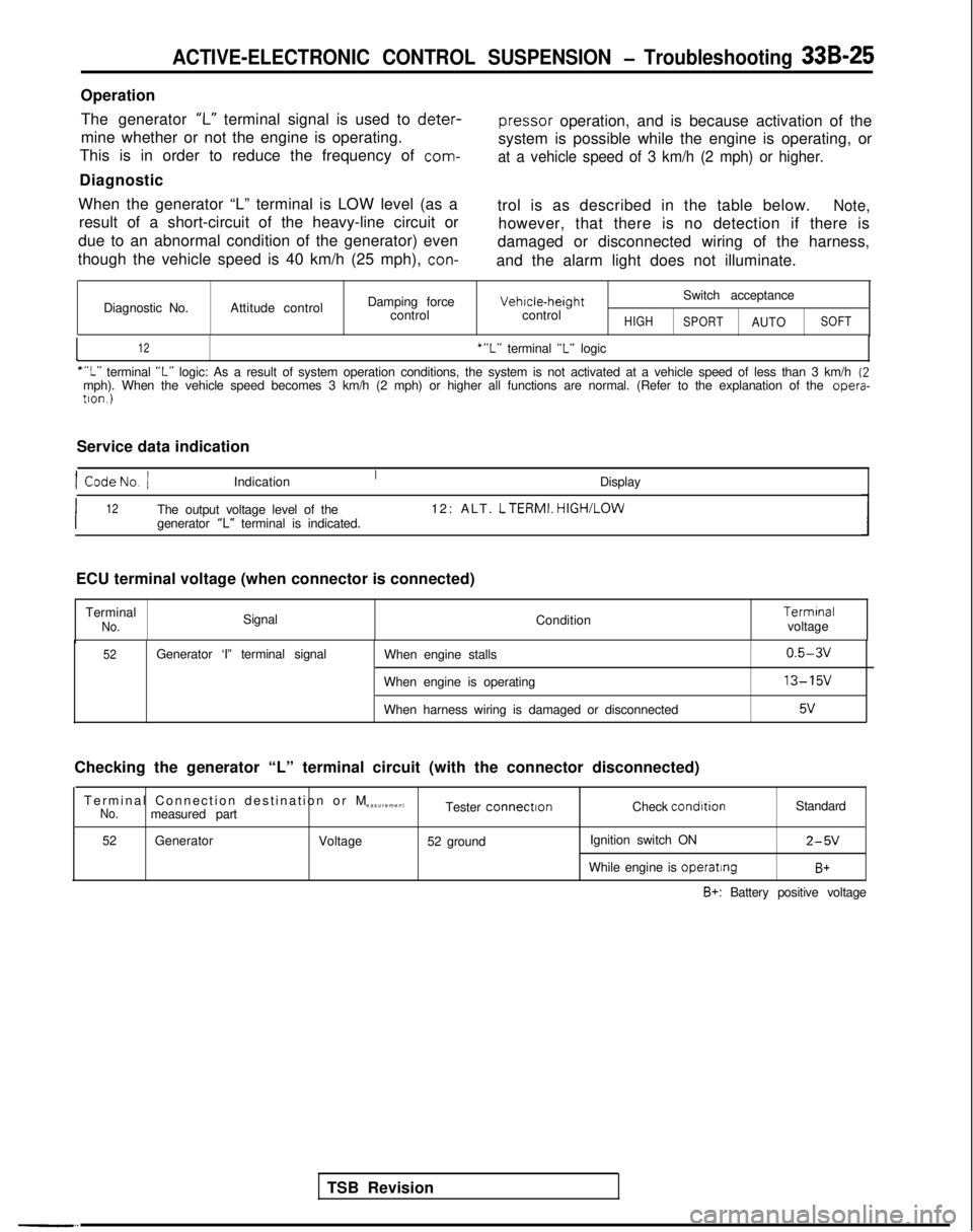
OperationThe generator
‘I-” terminal signal is used to deter-
pressor
operation, and is because activation of the
mine whether or not the engine is operating.
This is in order to reduce the frequency of
com-
system is possible while the engine is operating, or
at a vehicle speed of 3 km/h (2 mph) or higher.
Diagnostic
When the generator “L” terminal is LOW level (as a result of a short-circuit of the heavy-line circuit or
due to an abnormal condition of the generator) even
though the vehicle speed is 40 km/h (25 mph),
con-
trol is as described in the table below.Note,
however, that there is no detection if there is
damaged or disconnected wiring of the harness,
and the alarm light does not illuminate.
Diagnostic No. Attitude control Damping force
control Vehrcle-height
control
HIGH
Switch acceptance
SPORTAUTOSOFT
I12‘“L” terminal “L” logic
““L” terminal “L” logic: As a result of system operation conditions, the system is not ac\
tivated at a vehicle speed of less than 3 km/h (2mph). When the vehicle speed becomes 3 km/h (2 mph) or higher all fun\
ctions are normal. (Refer to the explanation of the opera-
tron.)
Service data indication
1 CodeNo. /Indication Display
I12The output voltage level of the12: ALT. LTERMI.
HIGH/LOW
generator “L” terminal is indicated.
TSB Revision
ECU terminal voltage (when connector is connected)
Terminal
No.Signal Condition Termrnal
voltage
52Generator ‘I” terminal signal When engine stalls
When engine is operating
When harness wiring is damaged or disconnected0.5-3v
13-15v
5v
Checking the generator “L” terminal circuit (with the connector d\
isconnected)
Terminal Connection destination or
M
easurement
No.measured part Tester connectronCheck condrtion
Standard
52 Generator
Voltage52 ground Ignition switch ON
2-5V
While engine is operatingB+
B+: Battery positive voltage
Page 966 of 1273
ACTIVE-ELECTRONIC CONTROL SUSPENSION - Troubleshooting 33B-27
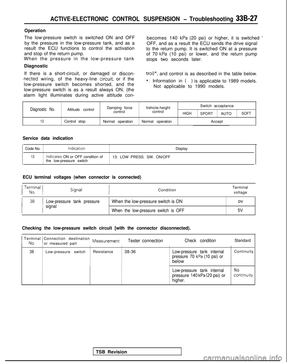
Operation
The low-pressure switch is switched ON and OFFby the pressure in the low-pressure tank, and as a becomes 140 kPa (20 psi) or higher, it is switched *
result the ECU functions to control the activation
OFF, and as a result the ECU sends the drive signal
and stop of the return pump. to the return pump. It is switched ON at a pressure
When the pressure in the low-pressure tank of 70
kPa (10 psi) or lower, and the return pump
stops two seconds later.
Diagnostic
If there is a short-circuit, or damaged or discon-
netted wiring, of the heavy-line
circuit,
or if the
low-pressure switch becomes shorted, and the low-pressure switch is as a result always ON, (the
trol)“, and control is as described in the table below.
alarm light illuminates during active attitude
con-
*: Information in () is applicable to 1989 models.
Not applicable to 1990 models.
Diagnostic No.Attitude control Damping force
Vehicle-height Switch acceptance
control controlHIGH
SPORTAUTOSOFT
13Control stop Normal operationNormal operation Accept
Service data indication
Code No.lndicatron
Display
13Indicates
ON or OFF condition of
13: LOW PRESS. SW. ON/OFF
the low-pressure switch
ECU terminal voltages (when connector is connected)
TSB Revision
/ Te;;,nal 1Condition Terminal
voltage
Low-pressure tank pressure
signalWhen the low-pressure switch is ONov
When the low-pressure switch is OFF5v
Checking the low-pressure switch circuit [with the connector disconnecte\
d).
I No.
Terminal Connection destination Measurement
!or measured partTester connectionCheck conditionStandard
38Low-pressure switch Resistance
38-36Low-pressure tank internalContinuit
y
pressure 70 kPa (10 psi) or
below
Low-pressure tank internalNo
pressure 140 kPa (20 psi) orcontinuity
higher.
Page 972 of 1273
ACTIVE-ELECTRONIC CONTROL SUSPENSION - Troubleshooting 33B-33
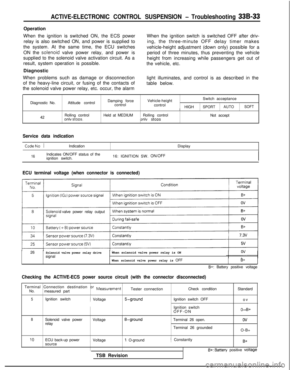
Operation
When the ignition is switched ON, the ECS power relay is also switched ON, and power is supplied to
the system. At the same time, the ECU switches
ON the solenoid
valve power relay, and power is
supplied to the solenoid valve activation circuit. As a
result, system operation is possible.
Diagnostic
When problems such as damage or disconnection of the heavy-line circuit, or fusing of the contacts of
the solenoid valve power relay, etc. occur, the alarm When the ignition switch is switched OFF after driv-
ing, the three-minute OFF delay timer makes
vehicle-height adjustment (down only) possible for a period of three minutes, thus preventing the vehicle
height from increasing while passengers get out of
the vehicle, etc.
light illuminates, and control is as described in the
table below.
Diagnostic No. 42 Attitude control
Rolling control
onlv stoos.
Damping force
Vehicle-height Switch acceptance
control control
/ HIGHSPORTAUTOSOFT
Held at MEDIUM
Rolling control
Not acceptonlv stoos
Service data indication
CodeNo /Indication Display
16Indicates ON/OFF status of the
iqnition switch. 16: IGNITION SW. ON/OFF
ECU terminal voltage (when connector is connected)
valve power relay output
26
Solenoid valve power relay drivesignalWhen solenoid valve power relay is ON
When solenoid valve power relay is OFFB+
B+: Battery positive voltage
Checking the ACTIVE-ECS power source circuit (with the connector discon\
nected)
Terminal Connection destination or Measurement ’No.measured part Tester connection
Check condition
5Ignition switchi Voltage5-groundIgnition switch OFF
Ignition switch
OFF-O
N
8Solenoid valve power
Voltage8-groundTerminal 26 open.
relay
Terminal 26 groundedStandard
o
v
O+B+
ov
O-B+
10ECU back-up power
sourcei Voltage1 O-ground
TSB Revision/ ConstantlyB+
B+: Batten/ positive voltage
Page 976 of 1273
ACTIVE-ELECTRONIC CONTROL SUSPENSION - Troubleshooting 33B-37
r
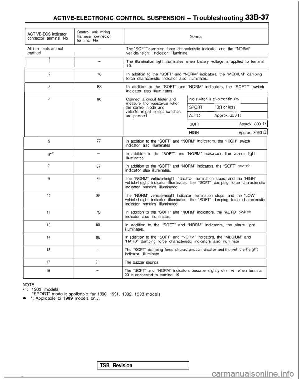
ACTIVE-ECS indicator
Control unit wiring
connector terminal No harness connector
Normal
terminal No
All termrnals
are not
I
-The’SOFT” damprng
force characteristic indicator and the “NORM”
earthed vehicle-height indicator illuminate.
I
1-1 The illumination light illuminates when battery voltage is applied to t\
erminali 19.
276In addition to the “SOFT” and “NORM” indicators, the “MED\
IUM” dampingi force characteristic Indicator also illuminates.
I3/88
In addition to the “SOFT” and “NORM” indicators, the “SOF\
T”*’ switch
indicator also illuminates.
I
Ll90Connect a circuit tester and
measure the resistance when
the control mode and
vehicle-height select switches
are pressed
1 b;h is pressed.1 E;i;yi;;a 1
SOFT1 Approx. 890 fZ 1
/ HIGH1 Approx. 3090 121
577In addition to the “SOFT” and “NORM”
Indicators.
the “HIGH” switch
indicator also illuminates 6*2
-In addition to the “SOFT” and “NORM” Indicators, the alarm light
illuminates.
787In addition to the “SOFT” and “NORM” indicators, the “SOF\
T” swatch indrcator
also illuminates.
975The “NORM” vehicle-height rndicator
illumination stops, and the “HIGH”
vehicle-height indicator illuminates; the “SOFT” damping force cha\
racteristic
indicator remains illuminated.
1085The “NORM” vehicle-height Indicator illumination stops, and the “\
LOW”
vehicle-height indicator illuminates; the “SOFT” damping force cha\
racteristic indicator remains illuminated.
1178In addition to the “SOFT” and “NORM” indicators, the “AUT\
O” switchindicator also illuminates.
1380In addition to the “SOFT” and “NORM” indicators, the alarm l\
ight
illuminates.
1486 In addrtion
to the “SOFT” and “NORM” indicators, the “MEDIUM” and\
“HARD” damping force characteristic indicators also illuminate
15-The “SOFT” damping force characterrstic
indicator and the vehicle-herghtindicator illuminate.
17
1971
-
The buzzer sounds.
The “SOFT” and “NORM” indicators become slightly
dimmer when terminal
20 is connected to terminal 19
NOTE*l:1989 models
“SPORT” modeisapplicable for1990, 1991,1992,1993models
l *: Applicable to 1989 models only.
TSB Revision
Page 980 of 1273
ACTIVE-ELECTRONIC CONTROL SUSPENSION - Troubleshooting 33B-41
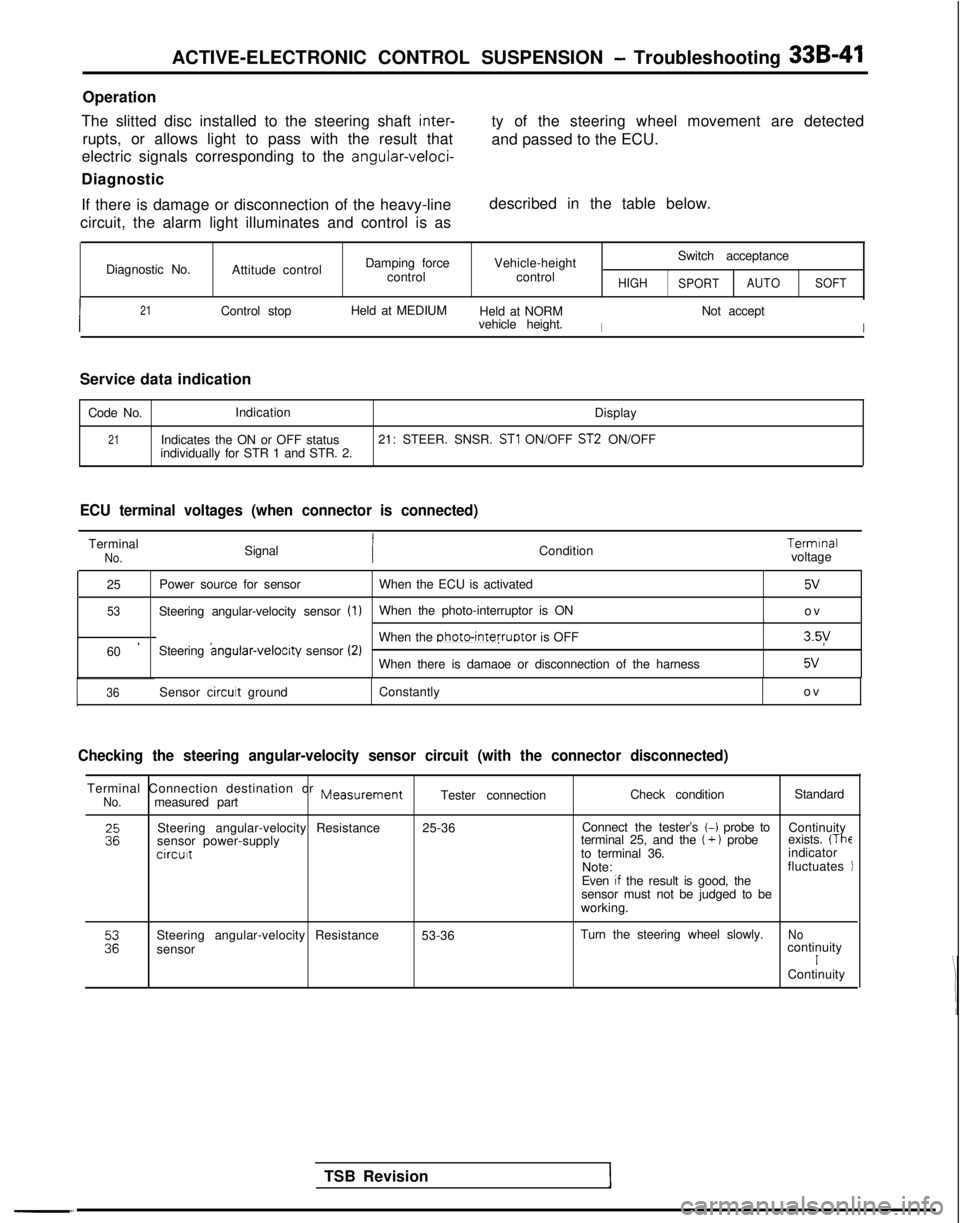
Operation
The slitted disc installed to the steering shaft
inter-
rupts, or allows light to pass with the result that
electric signals corresponding to the
angular-veloci-
Diagnostic
If there is damage or disconnection of the heavy-line
circuit, the alarm light illuminates and control is as ty of the steering wheel movement are detected
and passed to the ECU.
described in the table below.
Diagnostic No. Attitude control Damping force
control Vehicle-height
control
HIGH
Switch acceptance
SPORT AUTO
SOFT
I
21Control stop Held at MEDIUM
Held at NORM
I
Not accept
vehicle height.
I
Service data indication
Code No. Indication
Display
21Indicates the ON or OFF status21: STEER. SNSR. ST1 ON/OFF ST2 ON/OFF
individually for STR 1 and STR. 2.
ECU terminal voltages (when connector is connected)
TerminalNo.Signal Condition Termrnal
voltage
25 Power source for sensor
When the ECU is activated
5v
53Steering angular-velocity sensor (1)When the photo-interruptor is ON
o
v
60
’Steering angular-velocrty
sensor (2)When the photo-interruptor is OFF3.5y
When there is damaoe or disconnection of the harness5v
-“.
TSB Revision
36Sensor circuit
ground Constantly ov
Checking the steering angular-velocity sensor circuit (with the connect\
or disconnected)
Terminal Connection destination or MeasurementNo.measured partTester connection
Check condition
Standard
Steering angular-velocity Resistance
sensor power-supply
circut
25-36 Connect the tester’s t-i probe to
Continuity
terminal 25, and the (+ ) probe exists. (Theto terminal 36. indicator
Note: fluctuates
Even
If the result is good, the
sensor must not be judged to be
working.
Steering angular-velocity Resistance
sensor 53-36
Turn the steering wheel slowly.
NocontinuityIContinuity
Page 982 of 1273
ACTIVE-ELECTRONIC CONTROL SUSPENSION - Troubleshooting 33B-43
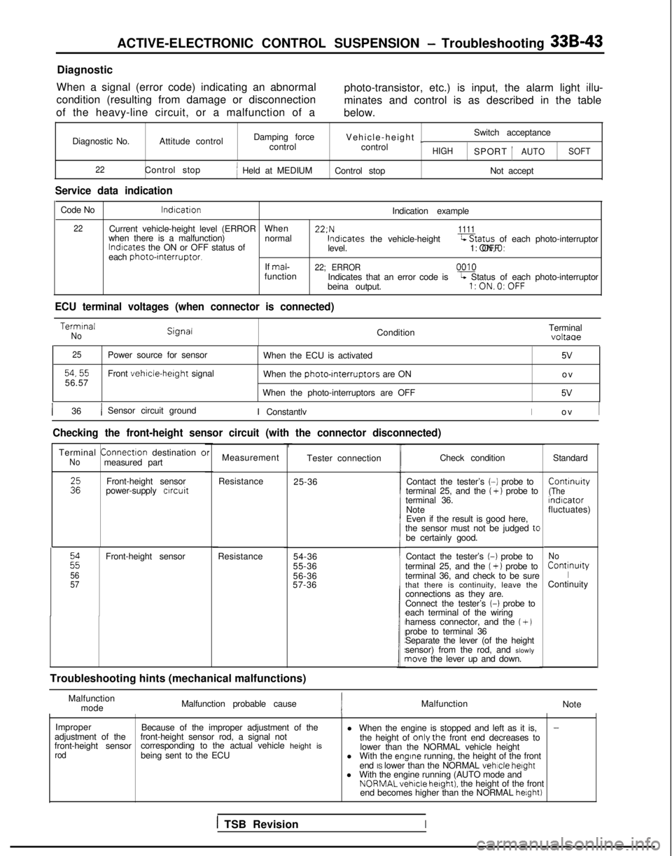
Diagnostic
When a signal (error code) indicating an abnormal
condition (resulting from damage or disconnection
of the heavy-line circuit, or a malfunction of a photo-transistor, etc.) is input, the alarm light
illu-
minates and control is as described in the table
below.
Diagnostic No. Attitude control Damping force
Vehicle-height
~Switch acceptance
control control
HIGHSPORT 1AUTOSOFT
22
Control stopj Held at MEDIUM Control stop Not accept
Service data indication
Code No lndrcation
Indication example
22Current vehicle-height level (ERRORWhen 22:N1111when there is a malfunction)
normallndrcates
the ON or OFF status of lndtcates
the vehicle-height-Status of each photo-interruptor
level. 1: ON,O: OFF
each
photointerruptor.If mal-22; ERRORfunction
0010
Indicates that an error code isL Status of each photo-interruptor
beina output.l:ON.O:OFF
ECU terminal voltages (when connector is connected) Termrnal
NoCondition
Terminalvoltaae
25
54,5556.57Power source for sensor
Front vehicle-herght signal
When the ECU is activated
5V
When the photo-rnterruptors are ON
o
v
When the photo-interruptors are OFF
5V
1 36/ Sensor circuit ground I ConstantlvIo
v
I
Checking the front-height sensor circuit (with the connector disconnect\
ed)
Terminal
Connectron
destination cNomeasured part
:zFront-height sensor
power-supply crrcuit
22
56
57
Front-height sensor
Resistance
brMeasurement
Resistance 25-36Tester connection
54-36
55-36
56-36
57-36
t
Troubleshooting hints (mechanical malfunctions) Check condition
Standard
Contact the tester’s
(-1 probe to Contrnuity
terminal 25, and the ( + ) probe to(Theterminal 36.
rndrcator
Note fluctuates)
Even if the result is good here,
the sensor must not be judged
tcbe certainly good.
Contact the tester’s
(-1 probe to
terminal 25, and the (+ 1 probe to
terminal 36, and check to be sure
that there is continuity, leave the
connections as they are.
Connect the tester’s
(-1 probe to
each terminal of the wiring
harness connector, and the
(+ Jprobe to terminal 36
Separate the lever (of the height
sensor) from the rod, and slowly
nave the lever up and down.
No Continurty
IContinuity
Malfunction mode Malfunction probable cause
Malfunction
Note
Improper Because of the improper adjustment of the
-adjustment of the
front-height sensorfront-height sensor rod, a signal not
l When the engine is stopped and left as it is,
corresponding to the actual vehicle height is the height of onlythe front end decreases to
rodbeing sent to the ECU lower than the NORMAL vehicle height
l With the engrne running, the height of the front
end IS lower than the NORMAL vehicle
height
l With the engine running (AUTO mode and NORMALvehicle
hetght). the height of the front
end becomes higher than the NORMAL helght)
1 TSB RevisionI
Page 984 of 1273
ACTIVE-ELECTRONIC CONTROL SUSPENSION - Troubleshootina 33B-45
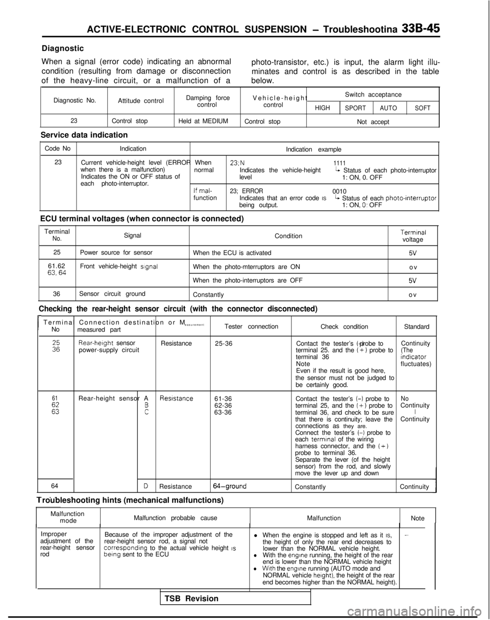
Diagnostic
When a signal (error code) indicating an abnormal condition (resulting from damage or disconnection
of the heavy-line circuit, or a malfunction of a photo-transistor, etc.) is input, the alarm light
illu-
minates and control is as described in the table
below.
Diagnostic No. Attitude control
23Control stop
Service data indication Damping force
control
Held at MEDIUM Vehicle-heigh
t
Switch acceptance
control
HIGH SPORT AUTOSOFT
Control stop
Not accept
Code No Indication
Indication example
23 Current vehicle-height level (ERROR When 23;N
1111when there is a malfunction)
normal
Indicates the ON or OFF status of Indicates the vehicle-height
levelL Status of each photo-interruptor
each photo-interruptor. 1: ON, 0. OFF
If mal-23; ERROR0010
function Indicates that an error code IS
being output.L Status of each photointerruptor1: ON, 0. OFF
ECU terminal voltages (when connector is connected) Terminal
No.Signal Condition
25 Power source for sensor
When the ECU is activated
61.62
63,64Front vehicle-height sIgnalWhen the photo-mterruptors are ON
When the photo-interruptors are OFF
36 Sensor circuit ground
Constantly Terminal
voltage
5v
o
v
5V
o
v
Checking the rear-height sensor circuit (with the connector disconnecte\
d)
rTerminal Connection destination or
M
easurement
No measured part Tester connection
Check conditionStandardRear-herght
sensor
power-supply circuit Resistance
25-36 Contact the tester’s (-) probe to
Continuity
terminal 25. and the
(+) probe to(Theterminal 36 indrcator
Note fluctuates)
Even if the result is good here,
the sensor must not be judged to be certainly good.
61
Es
Rear-height sensor A Resrstance
61-36No
F
Contact the tester’s (-)
probe to
62-36 terminal 25, and the ( +) probe toContinuity
63-36 terminal 36, and check to be sureIthat there is continuity; leave the Continuity
connections as they are.
Connect the tester’s
(-1 probe to
each termrnal
of the wiring
harness connector, and the
( +)probe to terminal 36. Separate the lever (of the height
sensor) from the rod, and slowly
move the lever up and down
64
- _. .
DResistance64-groundConstantly Continuity
1 roubleshooting hints (mechanical malfunctions)
Malfunctionmode Malfunction probable cause
MalfunctionNote
Improper Because of the improper adjustment of the l When the engine is stopped and left as it IS,
-adjustment of the
rear-height sensorrear-height sensor rod, a signal not
the height of only the rear end decreases to
rod correspondrng
to the actual vehicle height IS berng
sent to the ECU lower than the NORMAL vehicle height.lWith the engrne running, the height of the rear
end is lower than the NORMAL vehicle height
lWith the engine
running (AUTO mode and
NORMAL vehicle herght). the height of the rear
end becomes higher than the NORMAL height).
TSB Revision
Page 986 of 1273

ACTIVE-ELECTRONIC CONTROL SUSPENSION - Troubleshooting 33B-47
Operation
The vehicle-speed sensor is a reed switch type with pulse signals being \
sent four times for each rotation of
the transaxle output gear.
Diagnostic
If there is damage or disconnection of the heavy-line
the alarm light illuminates and control is as
de-
circuit, or a malfunction of the vehicle-speed sensor, scribed in the table below.
Diagnostic No. 24
Attitude control Damping force
Vehicle-height Switch acceptance
control controlHIGHSPORTAUTO SOFT
Control stop
Held at MEDIUMHeld at NORMAL
Not accept
Service data indication Code No lndrcation
Display
24 Indicates the vehicle speed Input
to
24: SPEED SNSR. 0 km/h
the ECU (including the simulated
vehicle speed)
ECU terminal voltages (when connector is connected)
ITerNmo_na’ConditionTerminal
voltage
I I
58 /
I
Vehicle-speed signal1 When the vehicle-speed sensor reed switch is ONo
v
IIII
*When the vehicle-speed sensor reed switch is OFF8V
TSB Revision
*In order to supply the EPS pull-up power
(8V)
Checking the vehicle-speed sensor circuit (with the connector disconnec\
ted)
Termrnal
Connectron
destination or M
easurement
No measured part
Tester connection
Check conditionStandard
58 Vehrcle-speed
sensor
Resistance
58-groundWith the battery’s (-1 termrnal
Continuity
disconnected, move the vehicleIback and forth.Nocontinuity
Troubleshooting hints In actual urban driving, it is not so likely that the
sensor fails.., ^_^.tnrottle IS kept 3U% or more open for more than 30
seconds. Therefore, the conditions have been This takes into account that the vehicle speed sen-
somewhat stricter to prevent unnecessary applica-
sor is shared by many systems such as EPS,
Auto-
tion of the fall safe function due to the racing of the cruise control, etc. and that the failure of the sensor
engine when stopped. However, the vehicle may can also be detected from the state of these sys-
terns.run uncontrolled for some distance when the speed