1989 MITSUBISHI GALANT Break
[x] Cancel search: BreakPage 542 of 1273
13-400AUTO-CRUISE CONTROL SYSTEM - Service Adjustment procedures
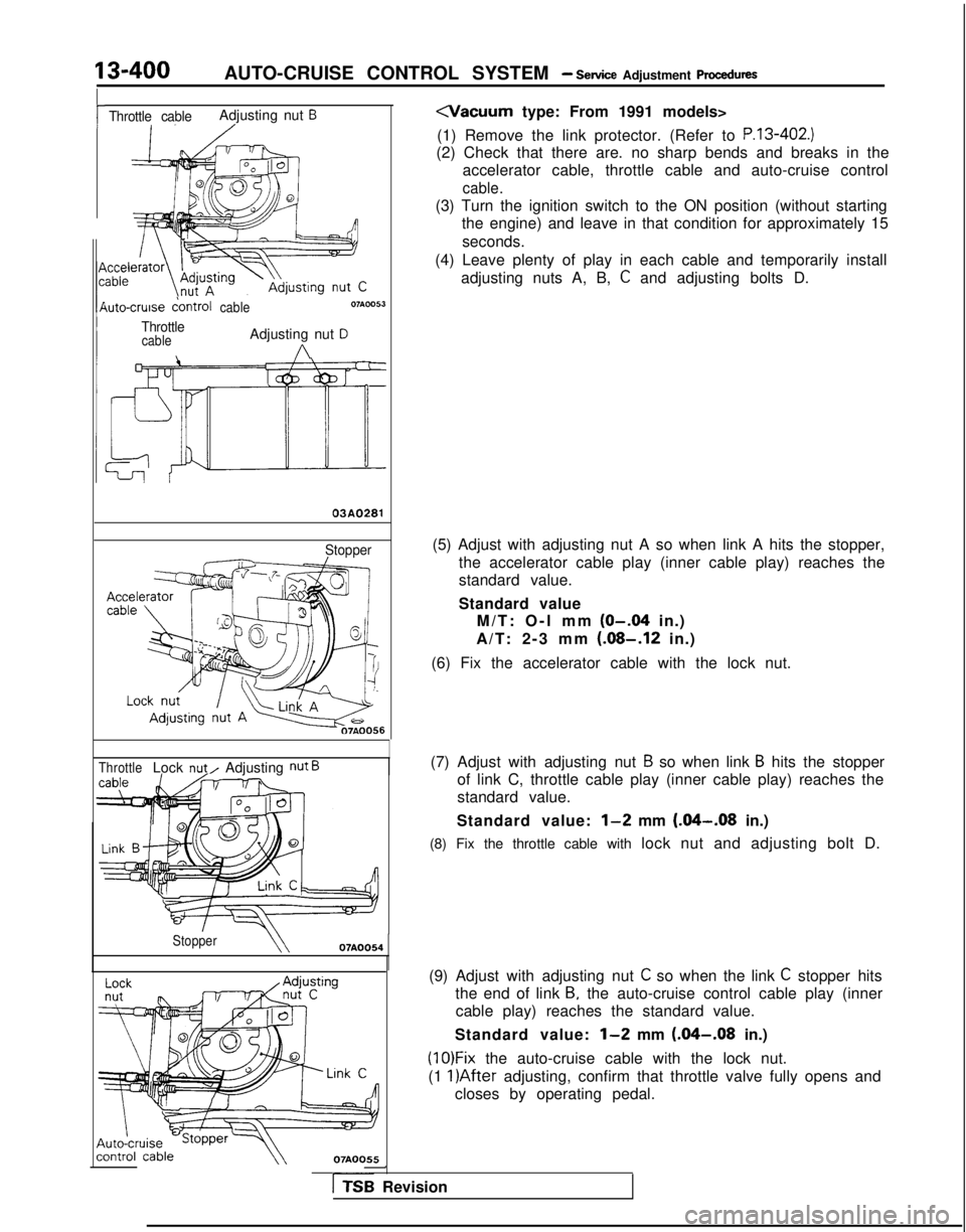
rThrottle cableAdjusting nut B
\uto-cruise dontrolcable
ThrottlecableAdjusting nut D
A
03A0281
Stopper
ThrottleLock nut/ Adjusting nut B
Stopper07AOO54
07AOO55
(1) Remove the link protector. (Refer to
P.13-402.)
(2) Check that there are. no sharp bends and breaks in the accelerator cable, throttle cable and auto-cruise control
cable.
(3) Turn the ignition switch to the ON position (without startingthe engine) and leave in that condition for approximately 15
seconds.
(4) Leave plenty of play in each cable and temporarily install adjusting nuts A, B,
C and adjusting bolts D.
(5) Adjust with adjusting nut A so when link A hits the stopper, the accelerator cable play (inner cable play) reaches the
standard value.
Standard valueM/T: O-l mm
(O-.04 in.)
A/T: 2-3 mm
(.08-.12 in.)
(6) Fix the accelerator cable with the lock nut.
(7) Adjust with adjusting nut
B so when link B hits the stopper
of link C, throttle cable play (inner cable play) reaches the
standard value.
Standard value:
l-2 mm (&I-.08 in.)
(8) Fix the throttle cable with lock nut and adjusting bolt D.
(9) Adjust with adjusting nut
C so when the link C stopper hits
the end of link
B, the auto-cruise control cable play (inner
cable play) reaches the standard value.
Standard value:
l-2 mm (.04-.08 in.)
(1O)Fix the auto-cruise cable with the lock nut.
(1
l)After adjusting, confirm that throttle valve fully opens and
closes by operating pedal.
-
rTSB Revision
Page 633 of 1273
EMISSION CONTROL SYSTEMS -Vacuum Hoses/Positive Crankcase Ventilation System17-13
INSPECTIONMl7JcAo
(1) Referring to the VACUUM HOSES ROUTING, confirm thatthe vacuum hoses are properly connected.
(2) Check the hoses for irregularities (disconnection, loose-ness, etc.) and confirm that there is no breakage or
damage.
INSTALLATION Ml7JDAD
(1) When connecting a hose, firmly press it onto the nipple.
(2) Referring to the VACUUM HOSES ROUTING, connect the hoses correctly.
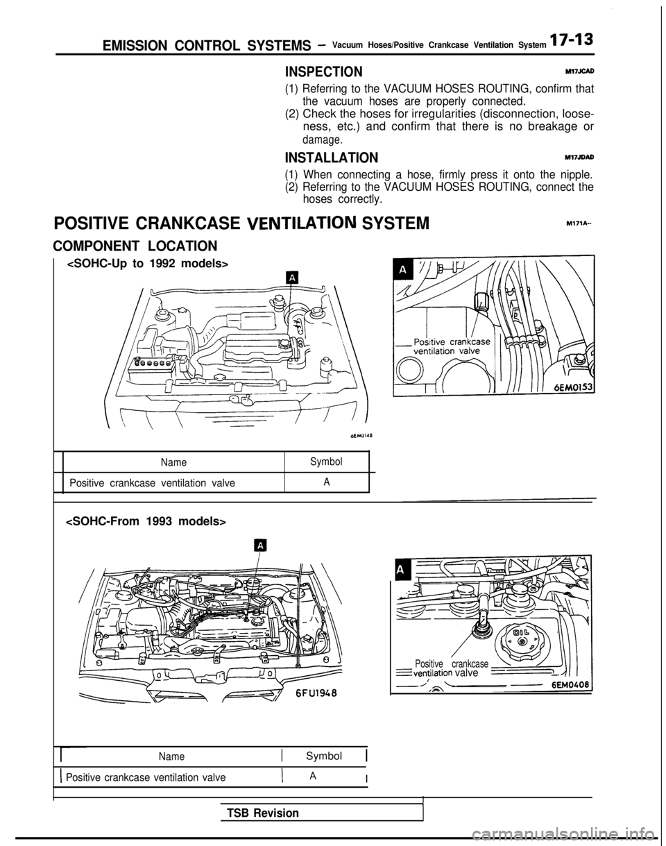
POSITIVE CRANKCASE VENTILATION SYSTEMM171A-
COMPONENT LOCATION
Name Symbol
Positive crankcase ventilation valveA
Name1 Symbol 1
1 Positive crankcase ventilation valveI A I
Positive crankcase---ventilation
valveI
ITSB Revision
Page 847 of 1273
FRONT AXLE -Drive Shaft (T.J.-R.J.
Type)26-17
INSPECTIONM26OGBC
l Check the drive shaft for damage, bending or corrosion.
l Check the drive shaft
splines for wear or damage.
lCheck for entry of water and/or foreign material into R.J.
l Check the spider assembly for roller rotation, wear or
corrosion.
lCheck the groove inside T.J. case for wear or corrosion.
l Check the boots for deterioration, damage or cracking.
SERVICE POINTS OF REASSEMBLY
MZbOHBE
9. INSTALLATION OF R.J. BOOT/6.
T.J. BOOT
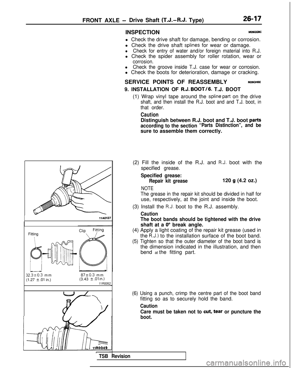
(1) Wrap vinyl tape around the
spline part on the drive
shaft, and then install the R.J. boot and and T.J. boot, in
that order.
Caution
Distinguish between R.J. boot and T.J. boot parts
according to the section“Parts Distinction”, and be
sure to assemble them correctly.
llAQl27
Fitting
32320.3 m
m
8720.3 m
m
(1.27
2 .Ol in.) (3.43 k .Ol u7.111 R005i
i-lj4AI Al II III L-1 llR0049ITSB Revision
(2) Fill the inside of the R.J. and R.J. boot with the
specified grease.
Specified grease:
Repair kit grease120 g (4.2 oz.)
NOTE
The grease in the repair kit should be divided in half for
use, respectively, at the joint and inside the boot.
(3) Install the
R.J. boot to the R.J. assembly.
Caution
The boot bands should be tightened with the drive
shaft at a 0” break angle.
(4) Apply a light coating of the repair kit grease (used in
the
R.J.) to the installation surface of the boot band.
(5) Tighten so that the outer diameter of the boot band is
the dimension indicated in the illustration, and thenbend at the fitting part.
(6) Using a punch, crimp the centre part of the boot band
fitting so as to securely hold the band.
Caution
Care must be taken not to cut,.tear or puncture the
boot.
Page 932 of 1273

FRONT SUSPENSION - Lower Arm33A-11
12u00~0
TSB tieviSion
L/&tag and excessive p\ay.
.\
SERVICE POINTS OF REMOVALM33N6AL
5. REMOVAL OF STABlLlZEk LINK MOUNTING NUTS
Using a wrench or similar tool to secure the ball studs at
both ends of the stabilizer link, remove the mounting nuts.
7. REMOVAL OF SELF-LOCKING NUT Using the special tool, disconnect the lower arm ball joint
from the knuckle.
Caution
1. Be sure to tie the cord of the special tool to the
nearby part.
2. Loosen the nut but do not remove it.
INSPECTIONM33NCAE
l Check the bushing for wear and deterioration.
l Check the lower arm for bend or breakage.
l Check the clamp for deterioration or damage.
l Check the ball joint dust cover for cracks.
l Check all bolts for condition and straightness.
CHECKING OF BALL JOINT FOR STARTING TORQUE
(1) If a crack is noted in the dust cover, replace it, adding
grease.
(2) Deflect from side to side the ball joint stud several times.
(3) Mount two nuts on the ball joint, and then measure the ball
joint starting torque.
Standard value:
3-10 Nm (26-87 in.lbs.)
(4) lf the starting torque exceeds the upper limit of standard
value, replace the lower arm assembly.
(5) Even if the starting torque is below the lower limit of the standard va\ue,
the ba\\ joint may be reused unless it has
Page 1043 of 1273
339-l 04 ACTIVE-ELECTRONIC CONTROL SUSPENSION - Lower Arm
SERVICE POINTS OF REMOVAL
hl33NBAC
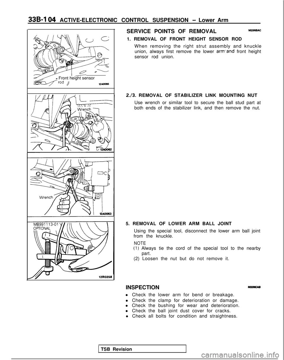
1. REMOVAL OF FRONT HEIGHT SENSOR ROD When removing the right strut assembly and knuckleunion, always first remove the lower arm’and
front height
sensor rod union.
yz--q--o .-L
T Front height sensor
lzAm66
12RO258
2./3. REMOVAL OF STABILIZER LINK MOUNTING NUT
Use wrench or similar tool to secure the ball stud part at
both ends of the stabilizer link, and then remove the nut.
5. REMOVAL OF LOWER ARM BALL JOINT Using the special tool, disconnect the lower arm ball joint
from the knuckle.
NOTE
(1) Always tie the cord of the special tool to the nearby
part.
(2) Loosen the nut but do not remove it.
INSPECTION
l Check the lower arm for bend or breakage. l Check the clamp for deterioration or damage.
l Check the bushing for wear and deterioration.
l Check the ball joint dust cover for cracks.
l Check all bolts for condition and straightness.
TSB Revision
Page 1073 of 1273

33B-134ACTIVE-ELECTRONIC CONTROL SUSPENSION - Air tube
Air
Tab
\Joint asset
MB991229nbly
12AO280
Dryer lower pa
\
t-t connection
part Flare-nut type
Loosen the joint and pull out the air tube.
NOTE
12A0278
When loosening the joint at the lower part of the dryer, use aspanner to hold the hexagonal part of the joint installation part
to prevent it from turning.
Caution
In order to prevent the entry of dust, foreign material, etc.,
use vinyl tape or similar material to close the end of the air
tube and the opening at the device side.
tLe*~Identification
colorJoint assembly 12AO363
1210278
SERVICE POINTS OF REMOVAL
REMOVAL OF AIR TUBES
One-touch type
(1) Push the special tool inward, in direction
0 shown in the
figure, in order to expand the tabs of the joint.
(2) Pull out the air tube, together with the special tool, in direction
0.
SERVICE POINTS OF INSTALLATION
INSTALLATION OF AIR TUBES
One-touch type Push the air tube in the joint assembly at the device side until
a “click” is heard, and then check to be sure that the tabs of
the joint assembly are securely affixed to the air tube.
Caution
Before connecting the air tube, check to be sure that the
identification color of the tube and the color at the joint
agree.
Flare-nut type
First insert the air tube until resistance is felt, and then press
the tube further inward to the paint mark on the air tube.
Caution
Air leakage may occur if the air tube connection is not
complete and secure.
INSPECTION AFTER AIR TUBE INSTALLATION
(1) Check for double-folding at the rolling diaphragm. (Refer to
P.33B-89.)
(2) Apply a soap-and-water solution to the joint part to check for air leakage; also visually check the air tube forbreakage, crushing, pinching, etc.
TSB Revision
Page 1110 of 1273
II12A0098
REAR SUSPENSION
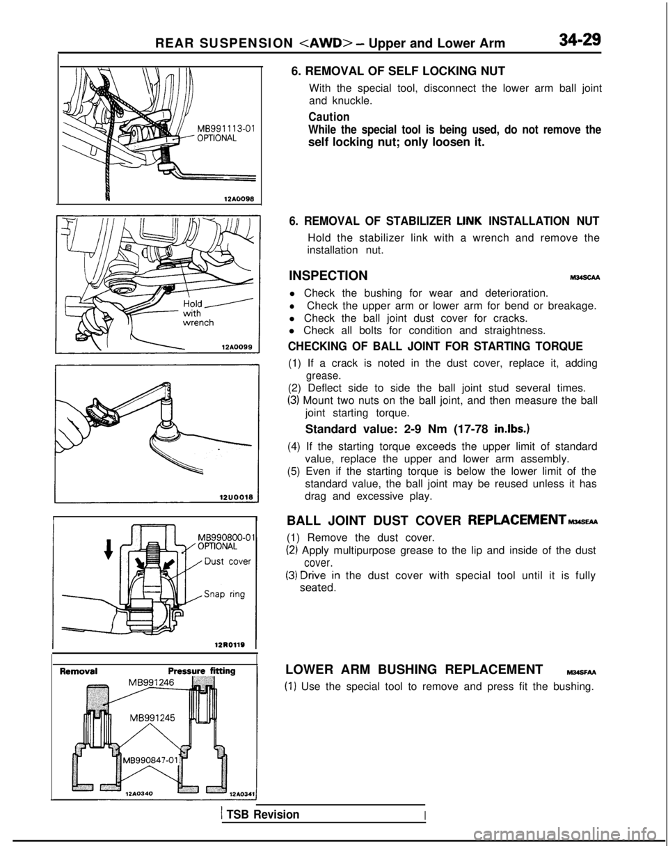
6. REMOVAL OF SELF LOCKING NUTWith the special tool, disconnect the lower arm ball joint
and knuckle.
Caution
While the special tool is being used, do not remove the
self locking nut; only loosen it.
II
I MB990800-0 1
6. REMOVAL OF STABILIZER LINK INSTALLATION NUT
Hold the stabilizer link with a wrench and remove the
installation nut.
INSPECTION l Check the bushing for wear and deterioration.
lCheck the upper arm or lower arm for bend or breakage.
l Check the ball joint dust cover for cracks.
l Check all bolts for condition and straightness.
CHECKING OF BALL JOINT FOR STARTING TORQUE
(1) If a crack is noted in the dust cover, replace it, adding
grease.
(2) Deflect side to side the ball joint stud several times.
(3) Mount two nuts on the ball joint, and then measure the ball
joint starting torque.
Standard value: 2-9 Nm (17-78
in.lbs.)
(4) If the starting torque exceeds the upper limit of standard value, replace the upper and lower arm assembly.
(5) Even if the starting torque is below the lower limit of the standard value, the ball joint may be reused unless it has
drag and excessive play.
BALL JOINT DUST COVER
REPLACEMENTn
(1) Remove the dust cover.
(2) Apply multipurpose grease to the lip and inside of the dust
cover.
(3) F;Fein the dust cover with special tool until it is fully
LOWER ARM BUSHING REPLACEMENT
MJOSFAA
(1) Use the special tool to remove and press fit the bushing.
1 TSB RevisionI
Page 1137 of 1273
35-16SERVICE BRAKES - Anti-lock Braking System Troubleshooting
TROUBLESHOOTING (ABS-FWD)
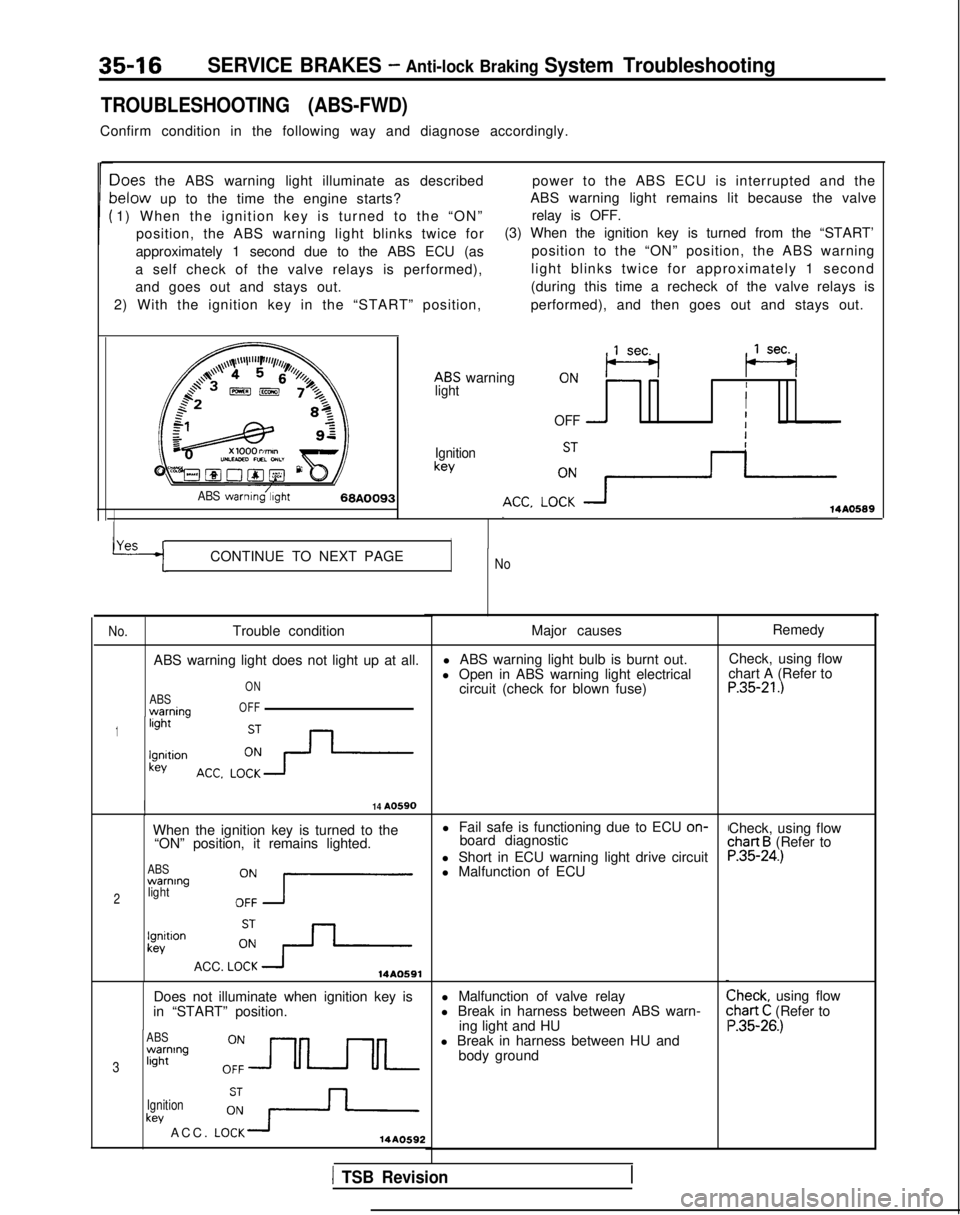
Confirm condition in the following way and diagnose accordingly.
Ioes the ABS warning light illuminate as describedpower to the ABS ECU is interrupted and the
lelow up to the time the engine starts?ABS warning light remains lit because the valve
1) When the ignition key is turned to the “ON” relay is OFF.
position, the ABS warning light blinks twice for (3) When the ignition key is turned from the “START’
approximately 1 second due to the ABS ECU (as position to the “ON” position, the ABS warning
a self check of the valve relays is performed), light blinks twice for approximately 1 second
and goes out and stays out. (during this time a recheck of the valve relays is
2) With the ignition key in the “START” position, performed), and then goes out and stays out.
ABS warning
,,lseq (se+
lightII
OFF -I
Ignitionkey
ABS warnmg/;,ght68A009314A0589
YAS rICONTINUE TO NEXT PAGENo
No.
Trouble condition
ABS warning light does not light up at all.
ABSwarnina
ON
OFF
1light -
lgnltionkey
I14 A0590
When the ignition key is turned to the l Fail safe is functioning due to ECU on-
“ON” position, it remains lighted. board diagnostic
ABSwarning
2lightOZ7
l Short in ECU warning light drive circuit
l Malfunction of ECU
lgnitlonkev
ACC. LOi+14A0591
Does not illuminate when ignition key is
in “START” position.
ABSwarning
3light
Ignition
key ACC. LO:+14AO592
Major causes
l ABS warning light bulb is burnt out.
l Open in ABS warning light electrical circuit (check for blown fuse)
l Malfunction of valve relay
l Break in harness between ABS warn- ing light and HU
l Break in harness between HU and body ground Remedy
Check, using flow
chart A (Refer to
P.35-21.)
Check, using flowchart B (Refer toP.35-24.)
Check, using flow:hart C (Refer to ‘.35-26.)
1 TSB Revision